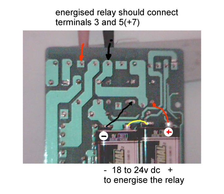
Clarke CL300
Clarke CL300
- This topic has 52 replies, 8 voices, and was last updated 5 December 2013 at 10:26 by
David Heath 1.
- Please log in to reply to this topic. Registering is free and easy using the links on the menu at the top of this page.
Latest Replies
Viewing 25 topics - 1 through 25 (of 25 total)
-
- Topic
- Voices
- Last Post
Viewing 25 topics - 1 through 25 (of 25 total)
Latest Issue
Newsletter Sign-up
Latest Replies
- Sat nag
- Angle grinder woes
- Bosch PBD 40 bearing upgrade
- Easiest/cheapest source of R8 socket
- Transwave converter – plugged in motor, tripped RCD
- in line oil check valve
- Old plastic handled screwdrivers
- motor and switch wiring Myford ML7
- Square end on round stock – Milling?
- File backup to external hard drive, incremental etc?


