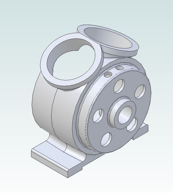
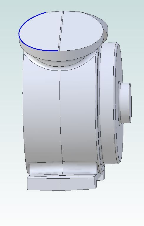
Now that I had the engine drawn out it was time to start converting the drawings to ones that could be used as patterns. Starting with the crankcase I made a copy of the file shown in my post above and then suppressed all the features that I did not need such as bearing hole, holes in the flanges for the cylinders to locate in, etc. I then added machining allowances where needed as well as draft angle so that the patterns could be pulled from the sand.

I decided it would be easiest to start by cutting two matching "halves" and then add the endplate with bearing boss as a third part so did a simple "extrude – cut" which left me with half a crankcase. I find that sometimes Alibre can have problems adding fillets to some internal corners once you start having more complex shapes joining at odd angles so left most of the fillets off the pattern file but will make use of the shape of the cutter to include them on the actual pattern.

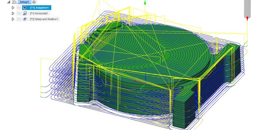
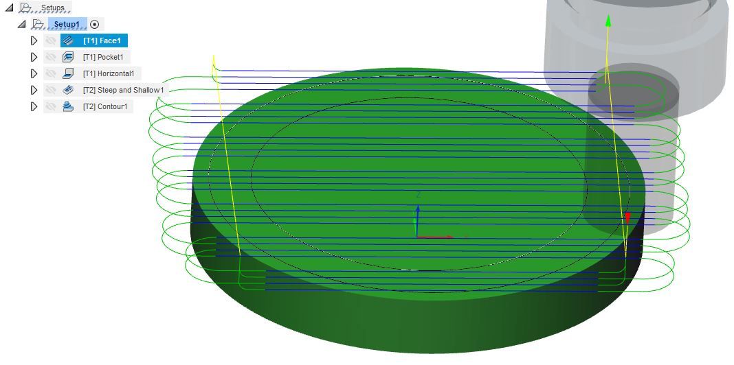
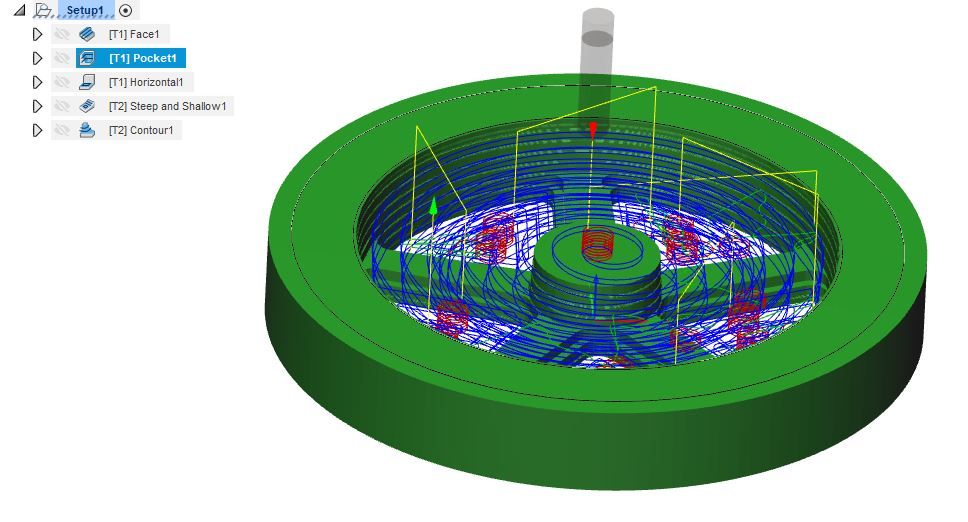
The file was then exported to Fusion 360 to do the CAM, I ended up with 3 separate strategies to produce the shape. Firstly an adaptive clearing one which is basically a roughing out pass leaving 0.5mm stock which was done with a long shank 4-flute carbide cutter at 5000rpm with a feed of 450mm/min taking most of the material off with a 5mm high by 1mm deep cut then just stepping up 1mm for the fine roughing which can better be seen on the next but one photo. The blue lines are the path that the centre of the end of the tool follows when cutting the yellow are where it is moving between cuts

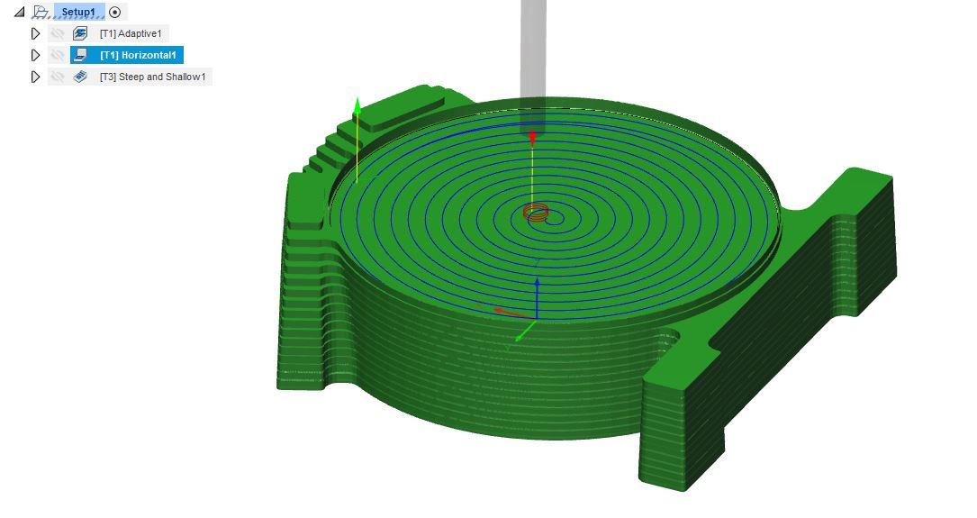
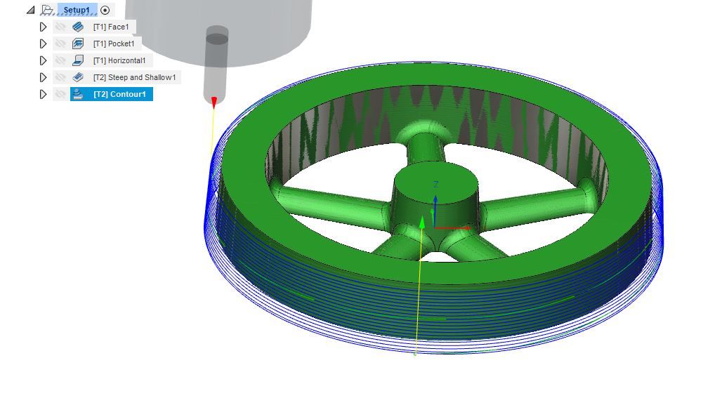
Next using the same tool and speeds but with a 4mm stepover the flat face had the final 0.5mm removed. you can see the stepped finish that the adaptive cuts left better in this photo as the tool paths don't get in the way.

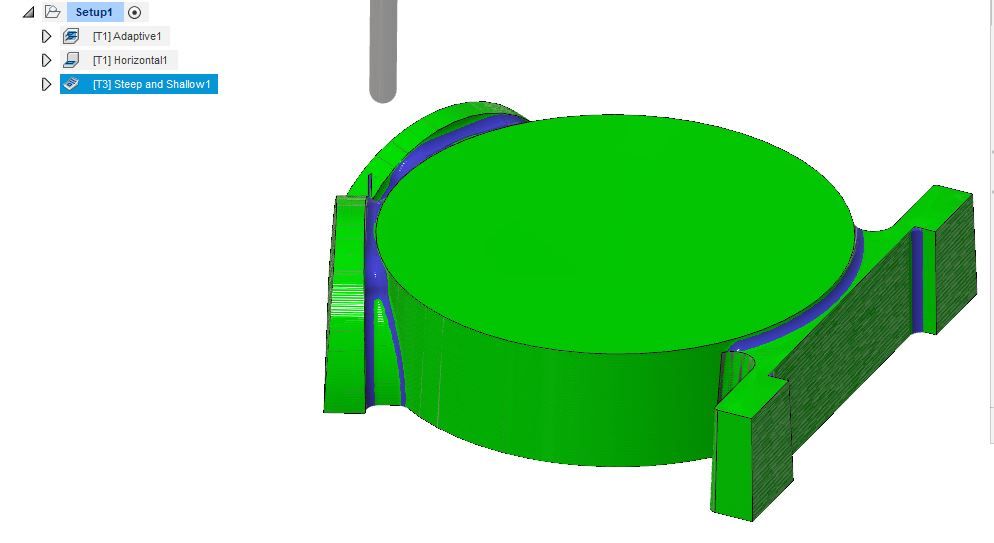
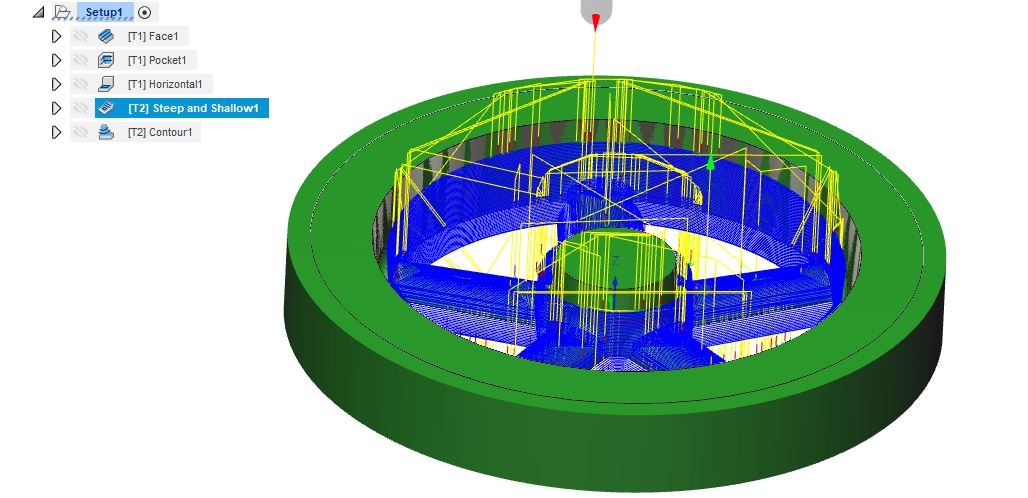
Finally a long shank 4-flute 6mm carbide ball nose cutter was used with a "steep and shallow" strategy that was set with a fine 0.33mm stepover or "scallop" between cuts again running at my max speed of 5000rpm but feeding a bit faster at 550mm/min

This image shows how F360's simulator will leave the finished part, the bright green areas are where it has cut to the drawn surface, the blue is material it has not removed which you can see is basically all the places where I wanted an internal fillet. This method works well on the easily cut wood but you do have to watch when doing it on metal as the percentage tool engagement can go up a lot and chatter is possible, in these cases it is better to try and draw in the fillets with a radius say 10% more than the radius left by the tool.

A couple of mouse clicks and the thousands of lines of G-code that F360 created were on a memory stick that could be transferred to the mill.
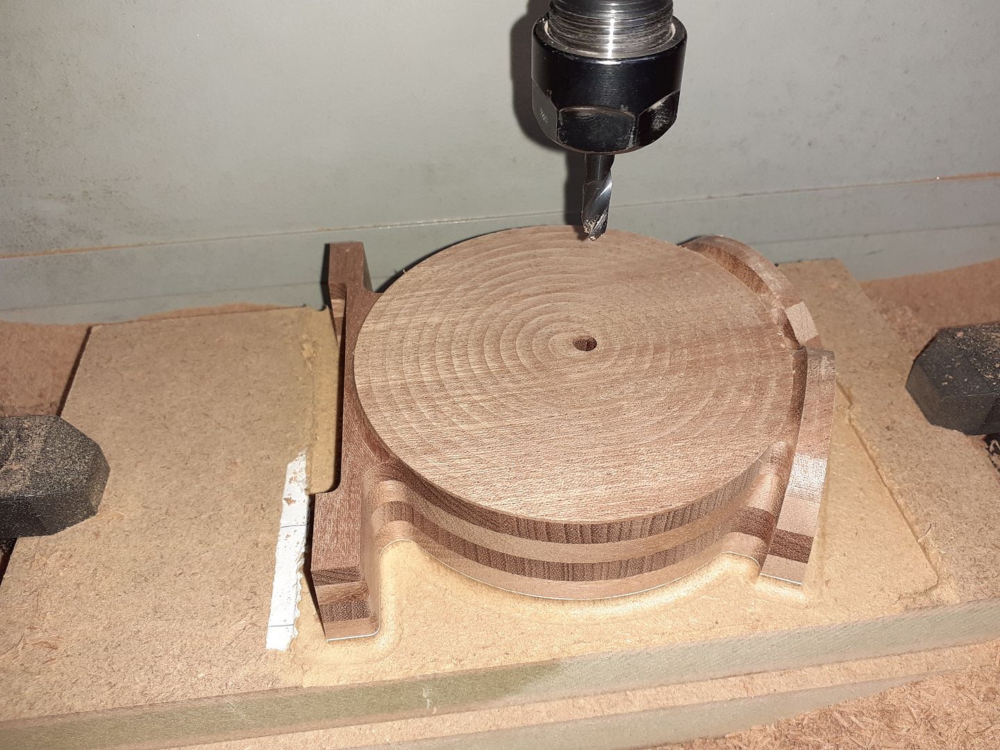
It was now time to cut some brown stuff, however I was wary that the flanges and particularly the feet could be broken off easily if the grain was not in the right direction. So rather than cut from a solid block of timber I laminated some thin boards of Sapele together which would have a similar effect to using plywood with it's grain that runs in two directions. I glued my blank to a piece of MDF with Titebond placing a sheet of copy paper in the joint which makes it easy to separate afterwards. Sorry No video of the crankcase being machined but this is after the final cuts with the ball nose tool and I also added a 6mm hole for later alignment.

Early on Graham had suggested that the crankcase could be cast without the need for a core which would save me time having to make a core box and also keep casting costs from the foundry lower. By having the external draft angles going each way from the split line but the internal angle being constant through both haves from the open side of the crankcase this is possible. So the next thing to do was glue the outer face of one half to another MDF clamping board and then glue the two mating faces of the pattern together both again with the sheet of paper.
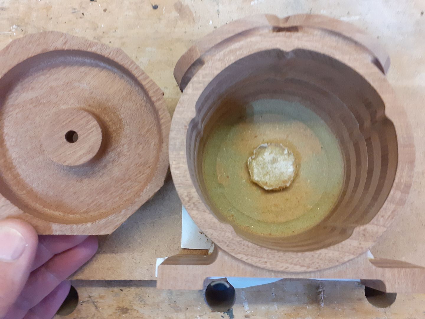
The inner cavity could then be roughed out with a long shank 10mm cutter and finished with a long shank 10mm ball nose cutter working it's way around the inside in a steadily lowering spiral. I also used the same cutter to form the inside profile of the end plate.

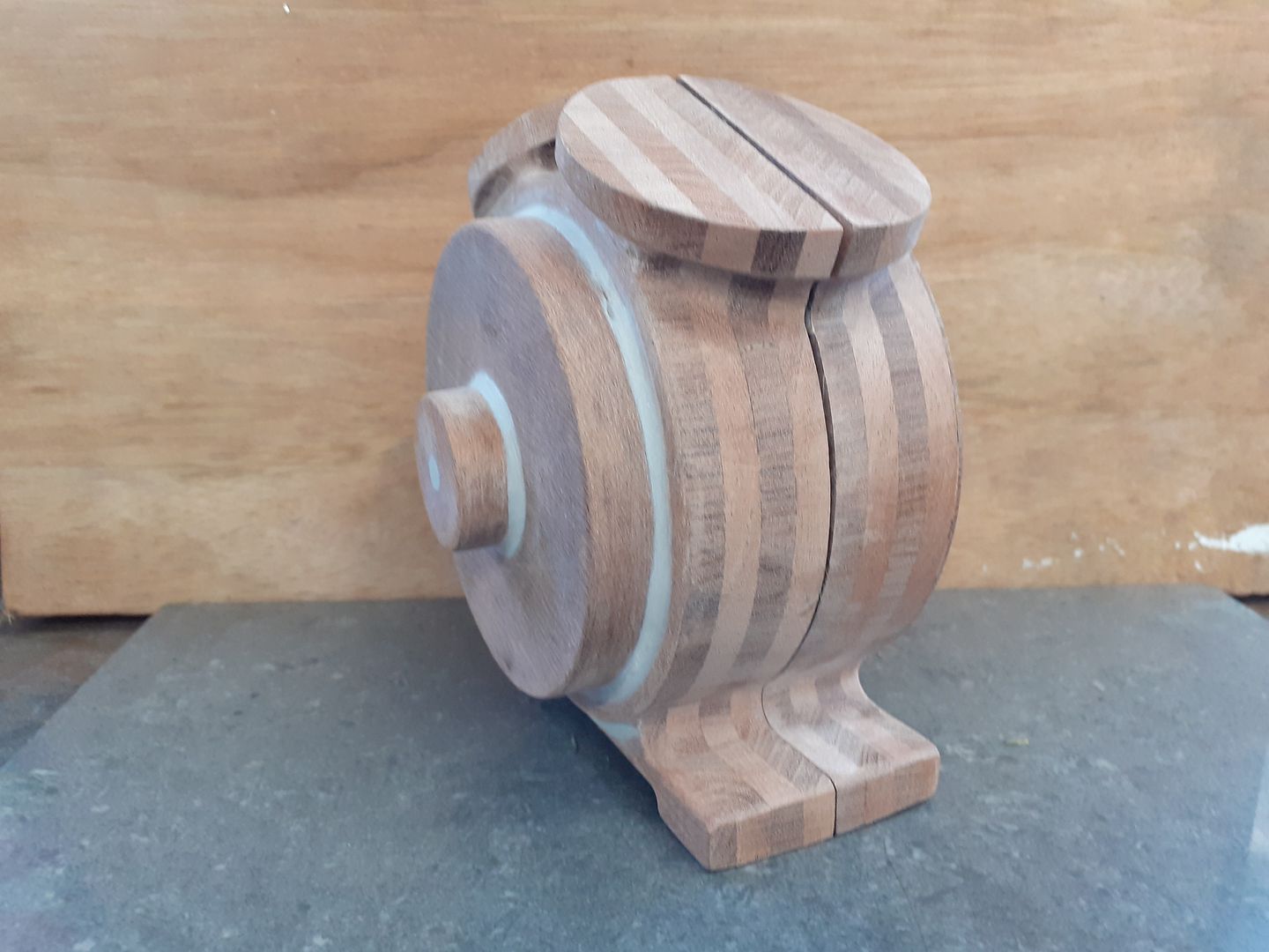
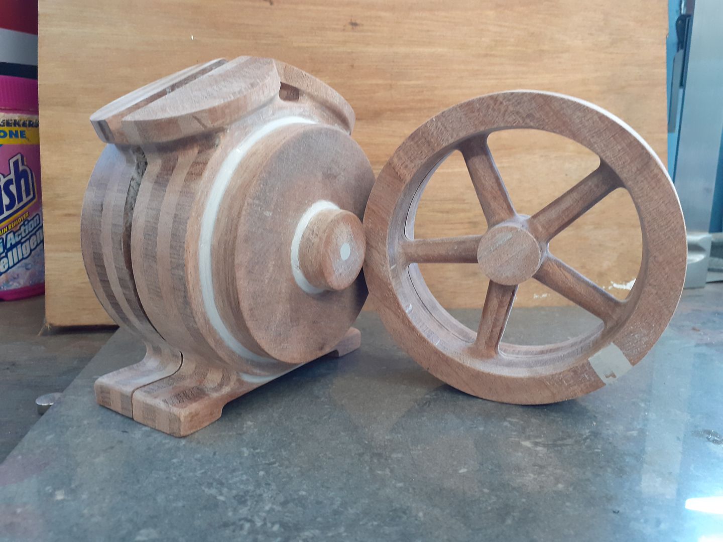
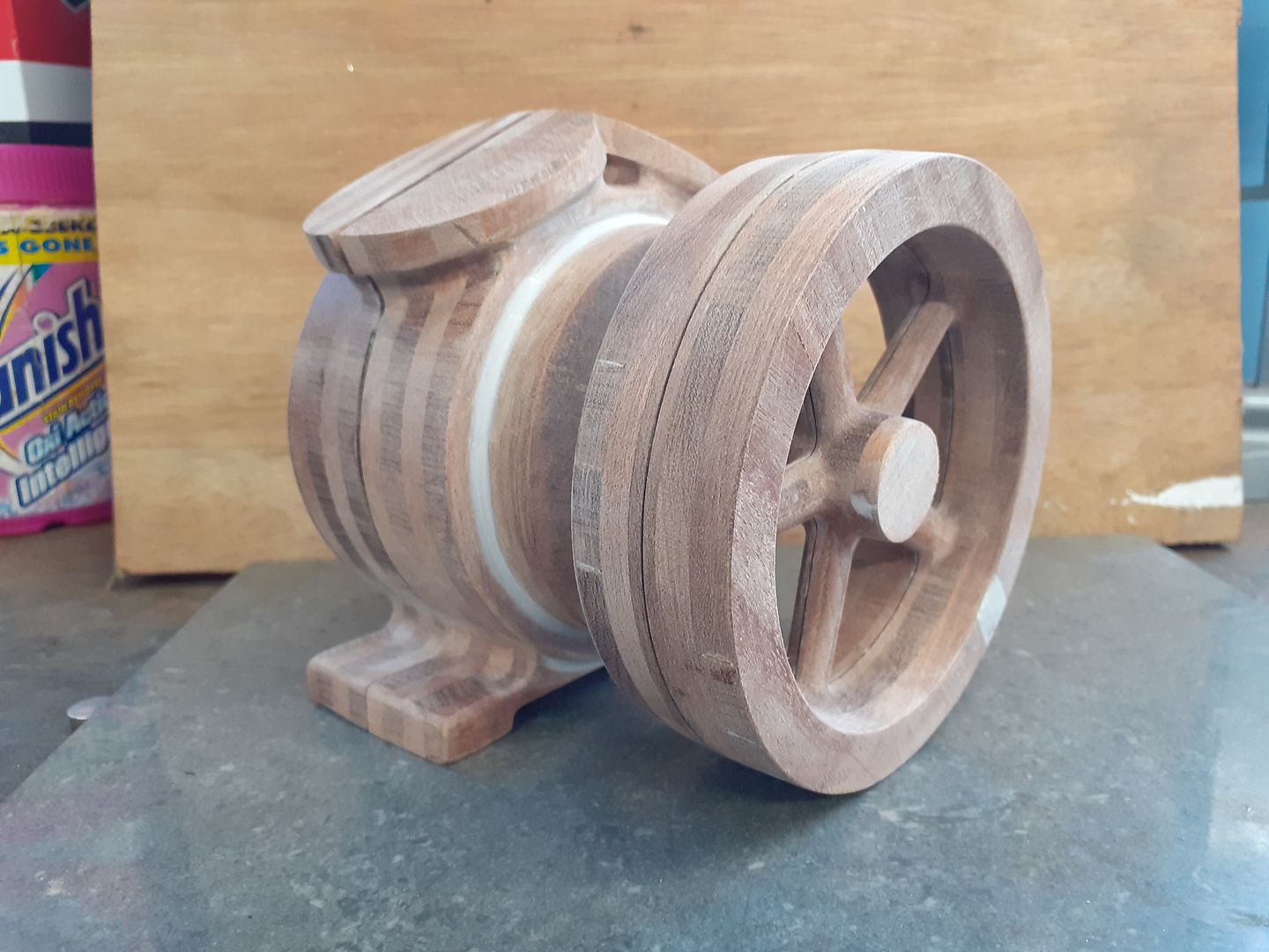
After separating the case from the clamping board and shaping the outside of the end plate the two were glued together and a fillet of filler added and sanded smooth. The actual surface of the wood needed hardly any sanding at all and came out far smoother than any of the hobby 3D printers would have done.


Ron Laden.


.JPG)
.JPG)
.JPG)



.JPG)
.JPG)
.JPG)
