Chester Super Lux advice
Chester Super Lux advice
Home › Forums › Manual machine tools › Chester Super Lux advice
- This topic has 174 replies, 22 voices, and was last updated 4 January 2025 at 16:47 by
 Taf_Pembs.
-
AuthorPosts
-
20 September 2024 at 21:21 #754656
 Taf_PembsParticipant@taf_pembs
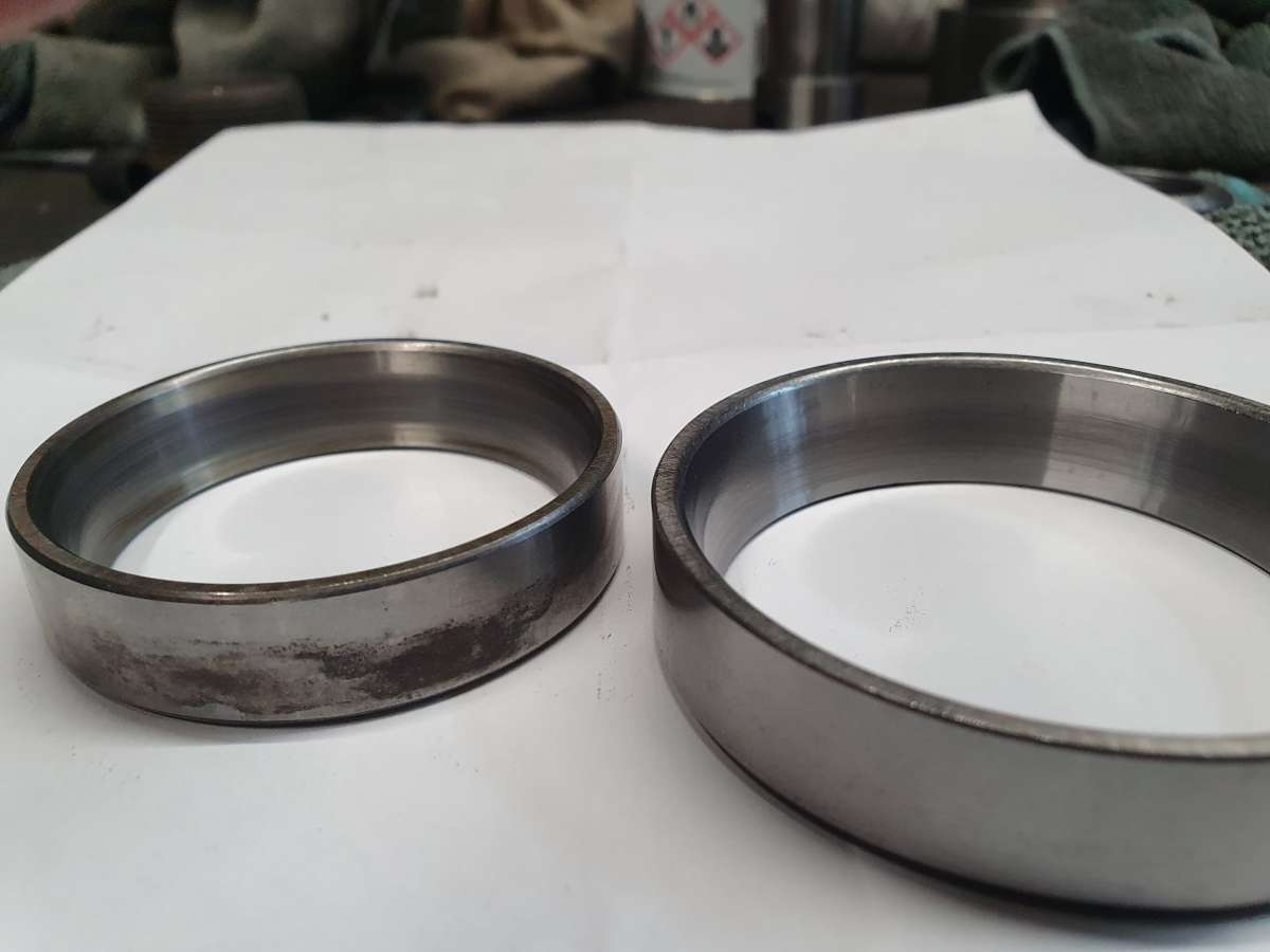
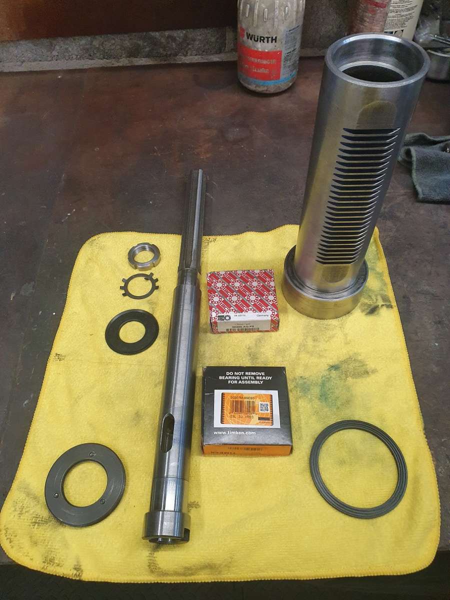
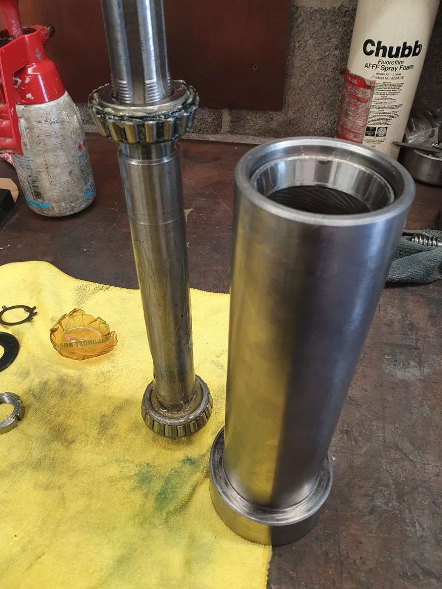
The upper bearing cup, on extraction, which wasn’t easy as it was a seriously tight fit – I had to warm the quill and still had to use a bit of serious welly to drift it out. Once out it was clear that there were significant areas of the cup that weren’t in contact with its seat in the Quill.

The wear marks on both cups is also off, just a small band in the middle (and rough!!)

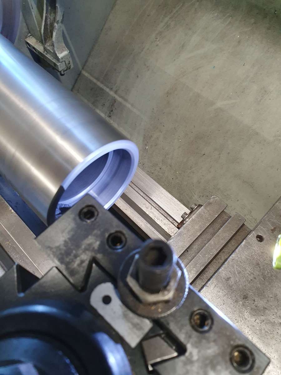
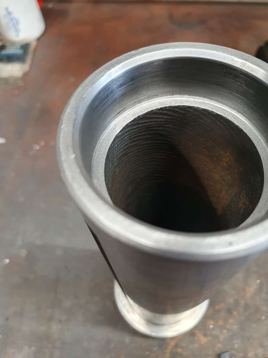
So I chucked up the quill in the 4 jaw and gave the upper cup seat a very light pass to see how it looked. It certainly wasn’t round, the outer ground surface of the quill was indicating within just about 0.01mm which I was utterly shocked about but the bearing seat was terrible.
I gave it a few very very light passes, again just using some freshly sharpened and pointy HSS so as to minimise contact pressure, and it came good just as I could press the cup in by hand so that’ll do with a bit of retainer too.

Poor picture sorry but you get the drift..
I’m yet to do another test assembly using the old bearings just to check everything again but I think I’m about there.
That’s about if for now, thanks for the comments from folk that are still interested in me continuing this, appreciate it and I’ll kep going till the end as long as people are still following. I know it’s not to everyone’s taste but I’m learning a shed load and really enjoying doing it 👍🍻
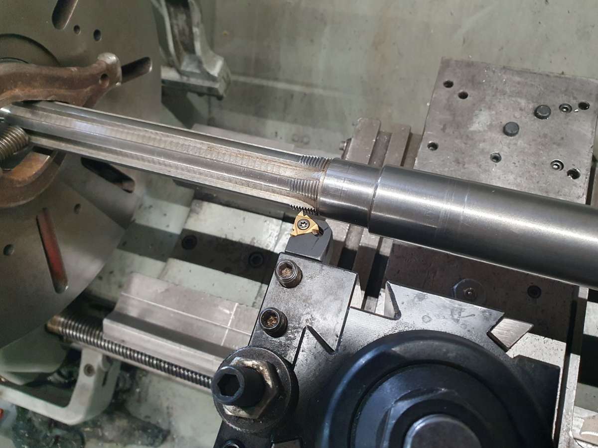
Oh, missed the pic of chasing the thread on the spindle so here you go (not that its very interesting!)

😊
22 September 2024 at 23:32 #755169Lathejack
Participant@lathejackYes keep it coming, I’m certainly still interested and following your progress with improving this machine.
26 September 2024 at 15:48 #756000 Taf_PembsParticipant@taf_pembs
Arf’noon all..
Cheers Lathejack, here’s a little more .. 👍
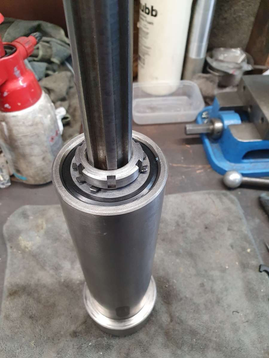
Where were we.. The Nut.
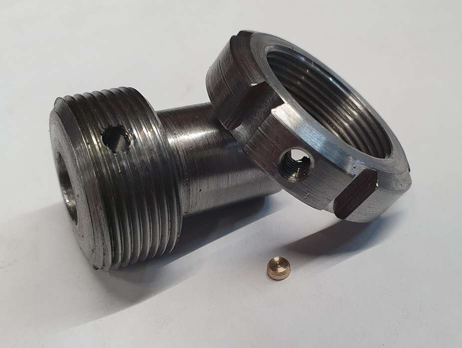
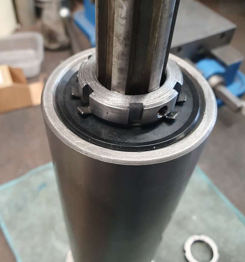
I made up an arbour so I could mount the nut in a collet chuck and then thanks AGAIN! to Mr J up the road and his mill the locking tab slots were all cut.

I also decided that on the chance that things line up nicely I put an M5 threaded hole for a locking screw in it too, easy to do and not an issue if not suitable – here with the arbour and the wee brass insert for the locking screw. Still a little cleaning up to do but turned out decent enough.

That’s another bit done.
26 September 2024 at 16:39 #756003 Taf_PembsParticipant@taf_pembs
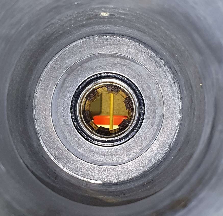
One thing about the spindle & quill set up that struck me when I was stripping the thing was that the splined drive collar that drives the spindle has shaft seals round it’s outer surface where it comes through the plate above the the Quill housing inside the gear head but there is nothing to prevent any ware material from the drive to the spindle splines, or any dirt / foreign crap that gets on the splines when getting to the drawbar on top of the spindle from getting straight down to the spindle bearings. Seemed a little odd 🤔
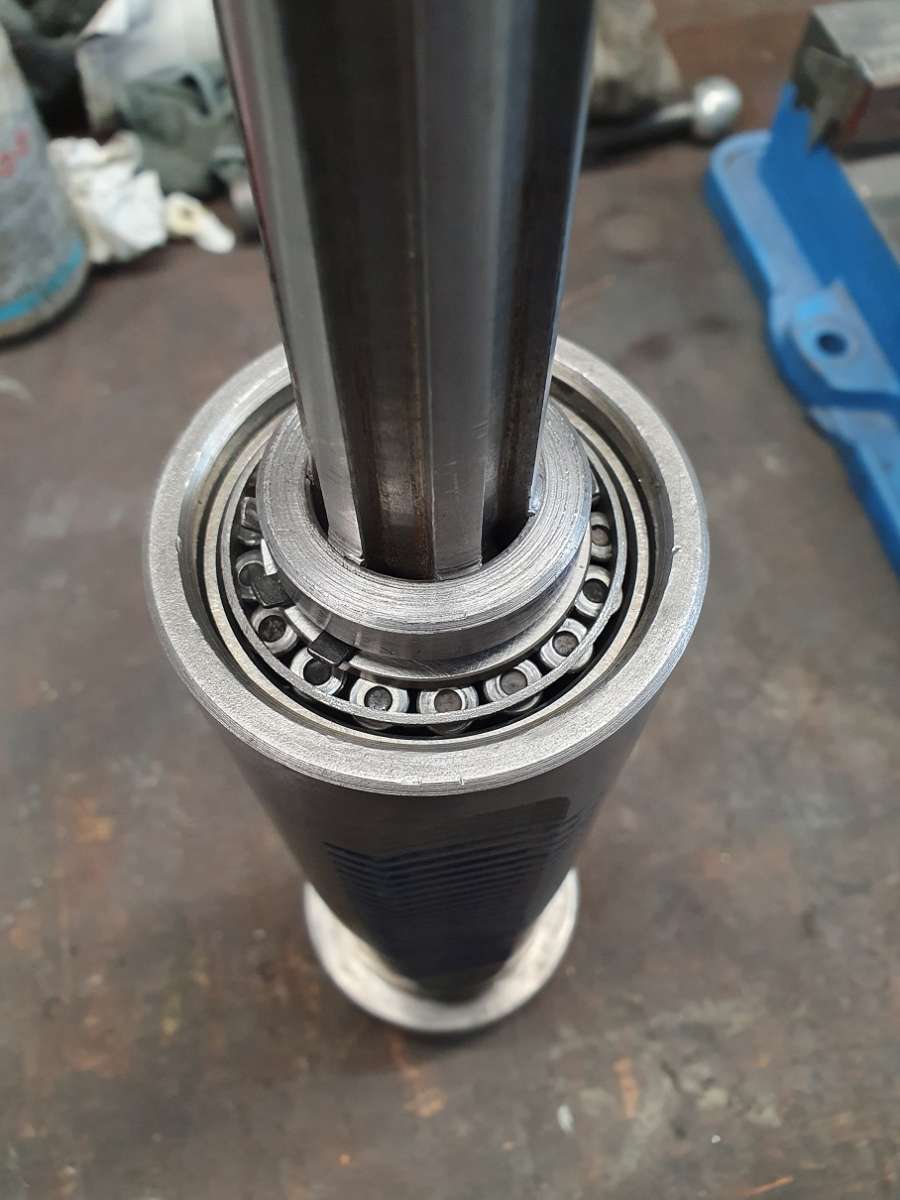
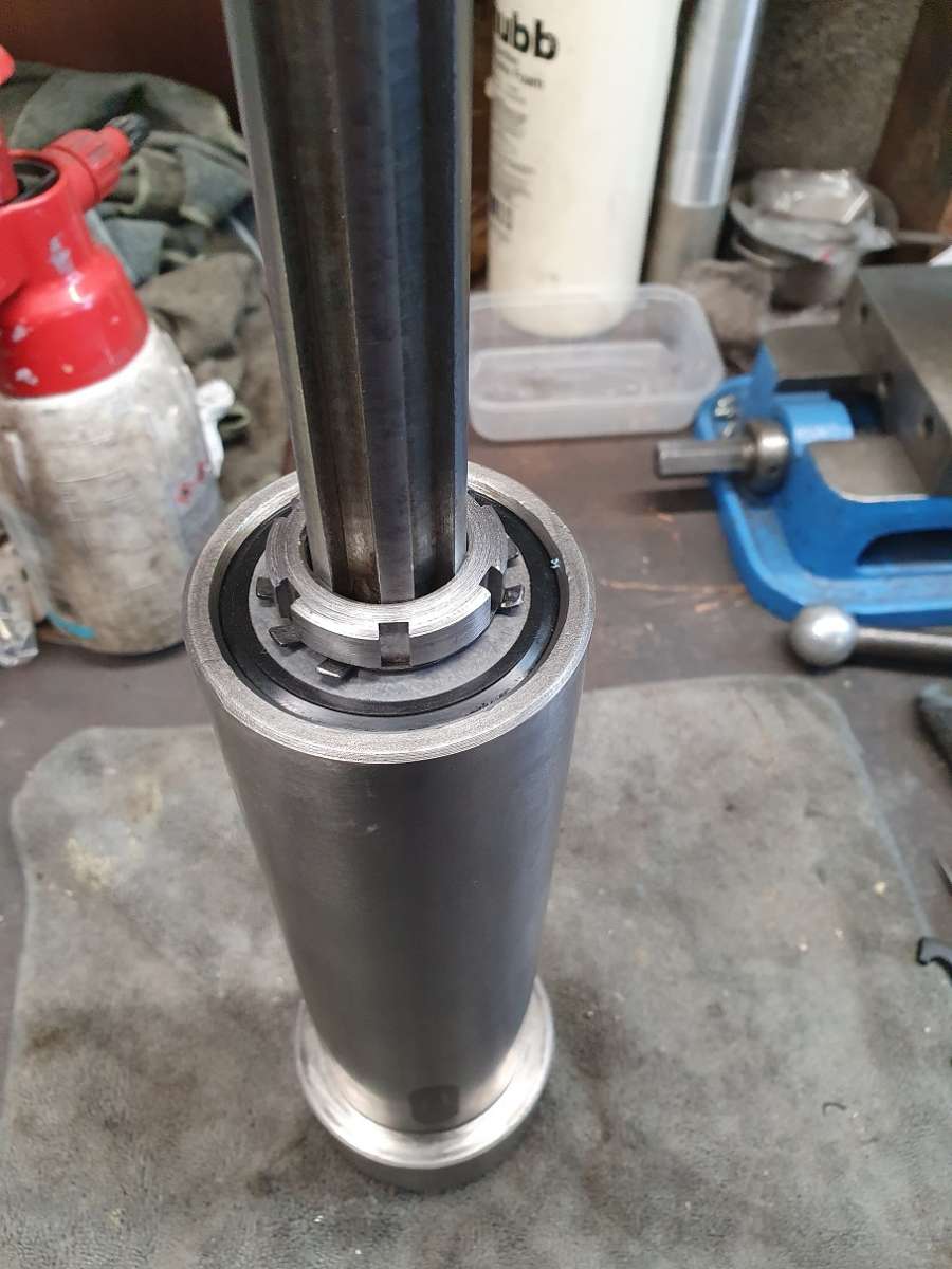
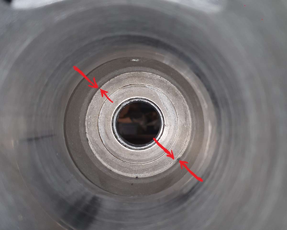
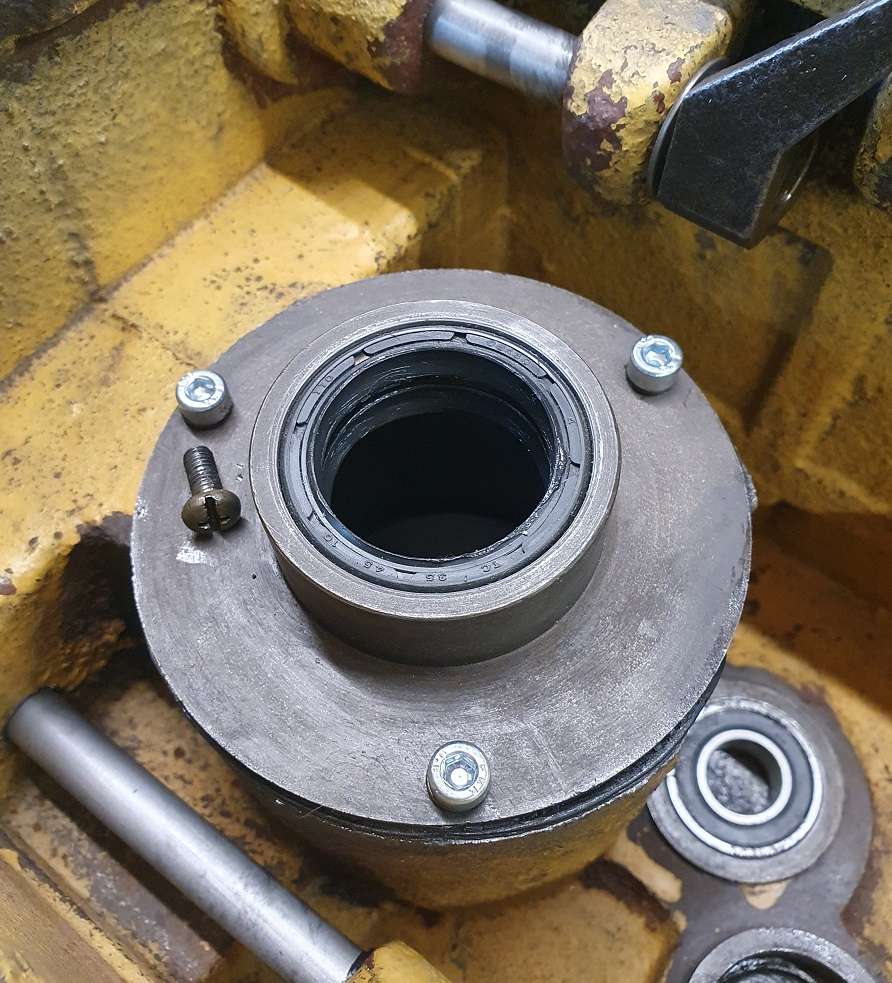
Here is the top of the quill showing the upper bearing, might make it easier to under stand what I’m trying to say, anything that gets on the splines can drop straight onto the upper bearing.

The bearing is just open. so I spent a few pence .. ok couple of quid on a flat hub seal, like is used on a lot of motorcycle upper steering head bearings. It is a very light touch fit to the quill but should certainly help prevent anything getting in there.

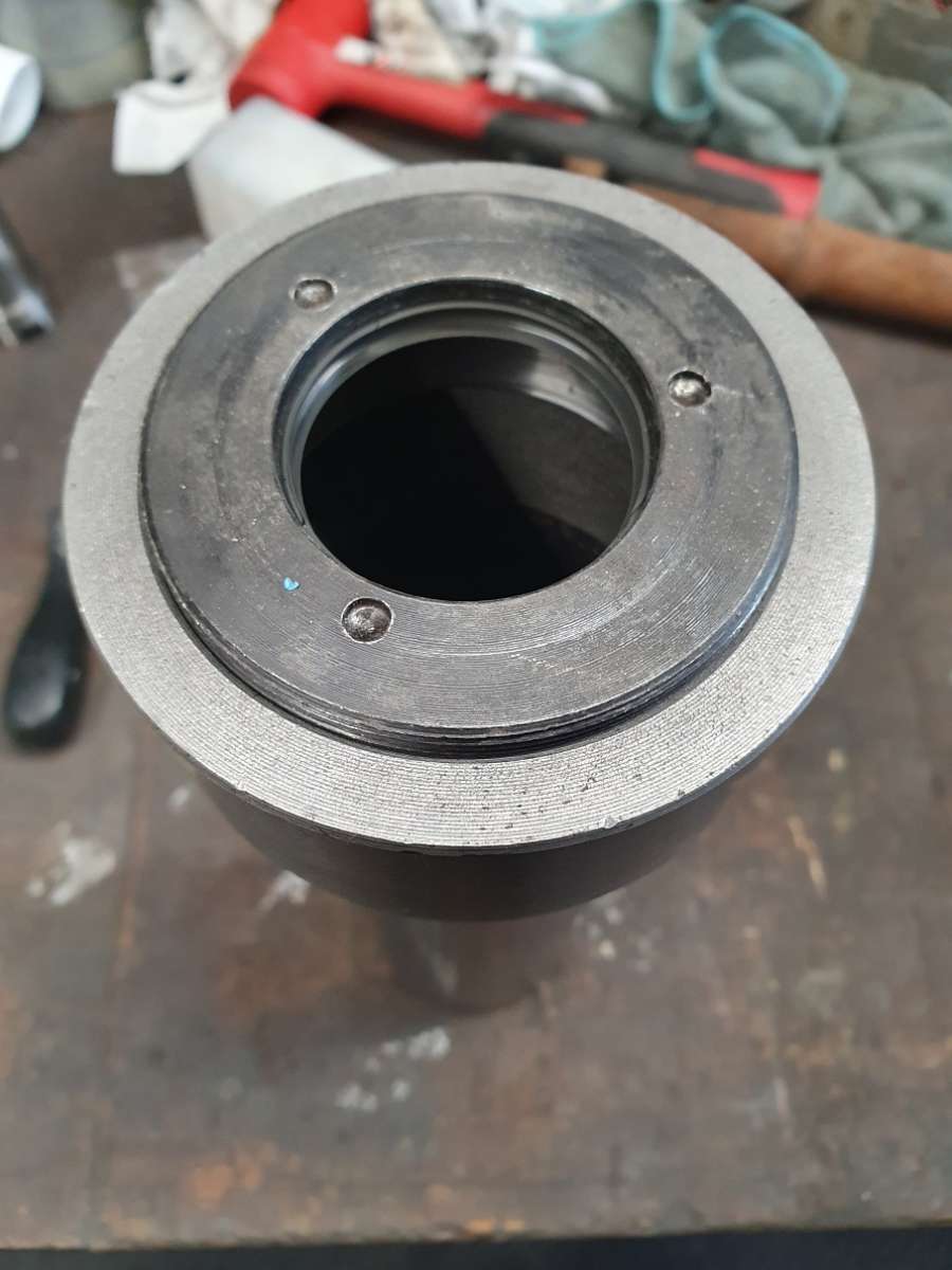
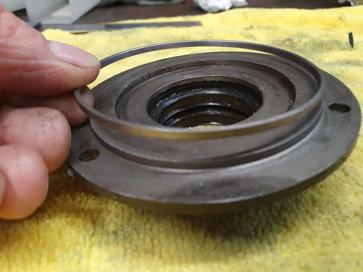
The bottom of the quill also only had a metal cover screwed into it with the best part of a 2mm gap between it and the protruding section of spindle, again leaving the lower bearing open to any coolant / bits that get sent in its direction. Grizzly call it a Spindle End Cap and Chester call it a Bearing Cup (although I don’t believe it contacts the bottom bearing cup, even when fully inserted it didn’t tighten up on it).
This is the cover fitted to the bottom of the quill (just pretend you cant see a seal in it!).

I checked the parts diagram for the Grizzly equivalent (kindly suggested by Robert Butler) and that shows a seal fitted into the cover.
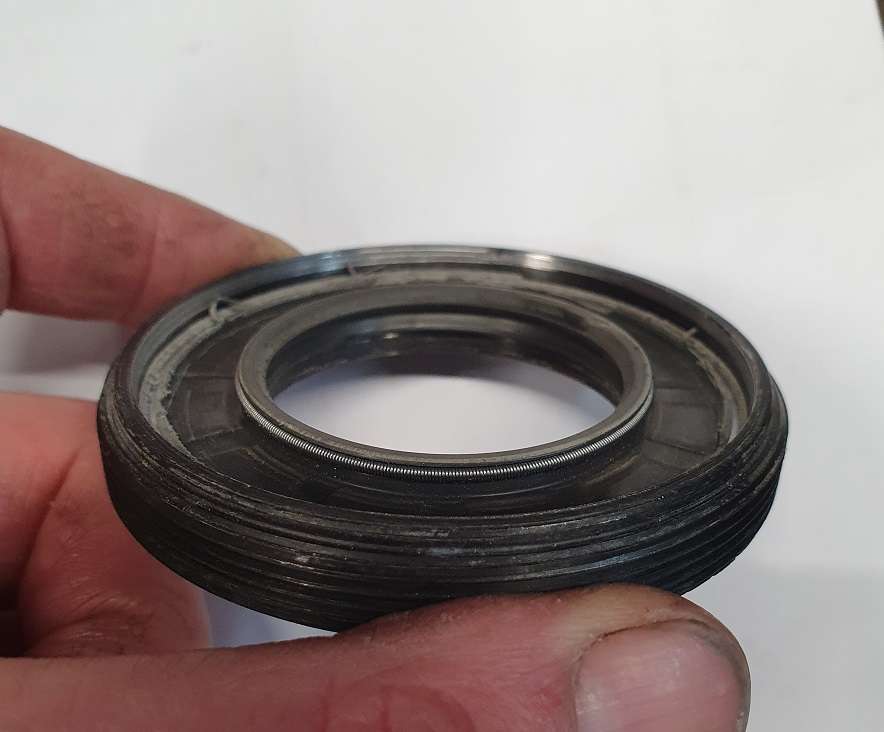
I ordered a seal and fitted it but when fitted onto the quill the outer lip on the seal was fouling the cage of the bottom bearing race so I used a small amount of glue to bond the seal inn, stuck it in the lathe and turned off the outer rim of the seal.

After a clean up it will now fit as before without interfering with anything.
I reassembled the spindle again (still using the old bearings just to check everything) and all seems tickety boo so that’s that job done!
Well.. it was until I decided that as it was all apart (or was!) now would be a the perfect time to have a go at making a captive drawbar then I don’t have to hit the thing again as they will be new bearings.
Oh well.. here goes.. 😬
So until I have done a bit of that – in the Buggs Bunny style – err That’s All Folks!
🍻
26 September 2024 at 16:53 #756010 Alan JacksonParticipant@alanjackson47790
Hi Taf,
Thank you for doing this most interesting write up on your soon to be super smooth mill. I found the way you found, analysed and solved the machine errors to be a roll model for others to follow and copy. You remind me of similar things I had to do with older worn machines.
Alan
26 September 2024 at 17:04 #756011 Taf_PembsParticipant@taf_pembs
Thanks Alan, really appreciate the comments!
It’s keeping me out of mischief and relatively sane while waiting for me to get fixed and more importantly keeping the grey matter occupied, just a shame I can only manage little bits here and there, should have been finished ages ago!
🍻
8 October 2024 at 22:34 #758080 Taf_PembsParticipant@taf_pembs
Evenin’ All!
Just having a quick re-read of my last update I forgot to mention that I’m not sure which way to mount the upper bearing cover seal that I’ve added.
As it is the seal lip is essentially upside down. My thinking is that as it is spinning any debris that lands on it will be flung up and out but being that way up means there is little or no contact with the quill so not ideal. If I mount it the other way up then there is a decent contact with the quill but leaving a small gully – for want of a better word – between the seal and the quill where debris could accumulate – as below.

This would obviously provide a better seal but the other option would be to recess the upper bearing cup in the quill be about 0.5mm or so allowing the seal in the inverted fitment to create a light seal to the quill while also having the upward sloping lip to help get rid of any debris. I suppose if fitted as in this pic above then a coating of grease would help prevent any nasties from getting in. The other down side is it created a reasonable amount of friction making ‘feeling’ the bearing preload somewhat difficult but the temp of them will soon sort that I suppose. Not decided which way to fit it yet.
Every day there is a decision to make….🙄
8 October 2024 at 23:53 #758084 Taf_PembsParticipant@taf_pembs
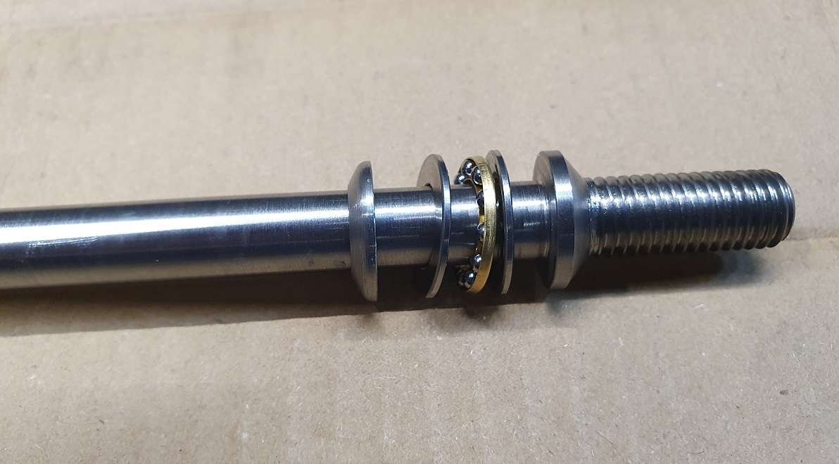
Anyway, this captive drawbar milarky.. Oh go on then I thought, lets have a go.. I had a quick scan of the interweb and it seems some like them and some don’t but they all seem pretty similar although not seen any with a thrust bearing. I’ll pass judgement when I’ve given it a chance.
Failing that I might try that DIY power drawbar using one of those low power butterfly air wrenches although that’s a far bigger project than a captive bar.
I know a well snugged up MT3 takes a fair force to remove it but only 1 way to find out !
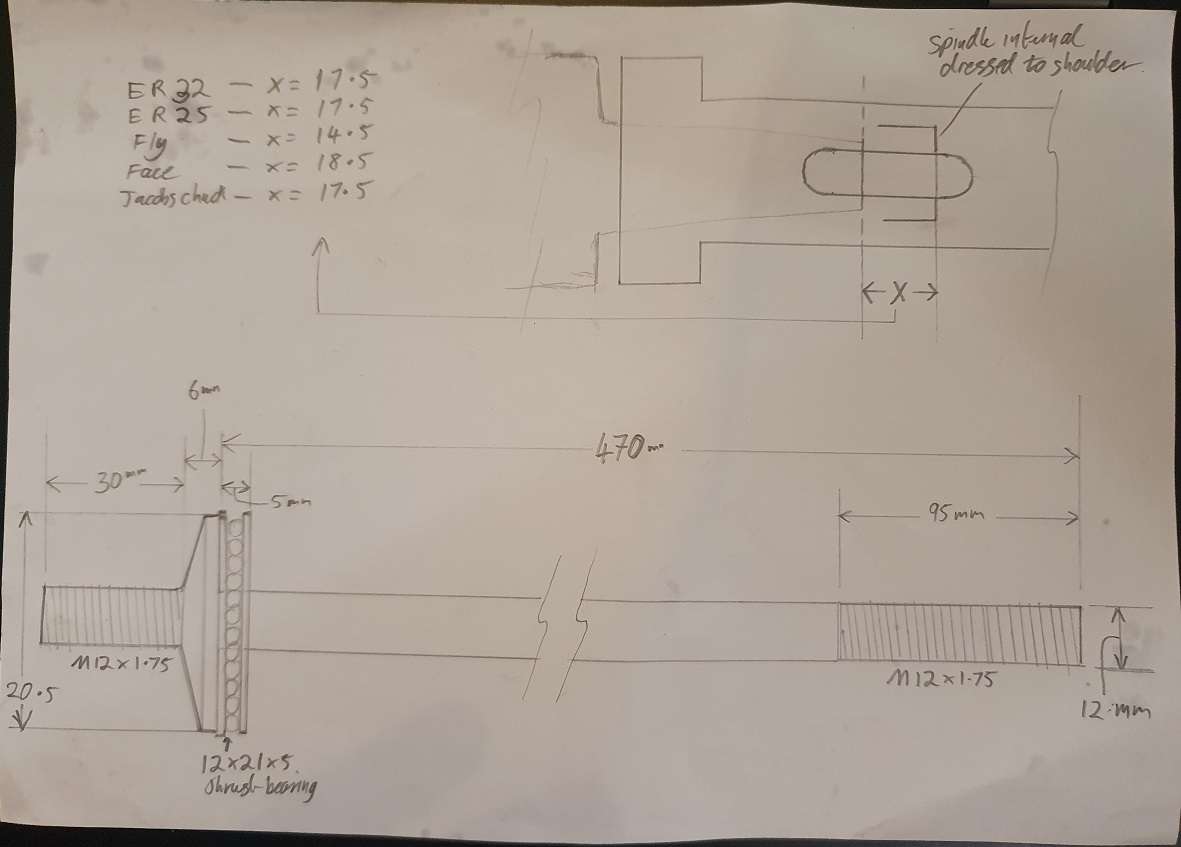
For once I thought I best take some proper measurements and make a rough drawing – which I have re drawn for this pic as I spilt oil on it!

I thought I’d fit a thrust bearing to remove any friction and hopefully make the removal easier.
I set up a small boring bar with a ridiculous amount of stick out (hence the fairly poor finish) and dressed the internal area of the spindle to clean up the rough cast area which as luck would have it was just enough to bring it to a hair over 21mm which is the same as the small end of the morse taper.
I then extended it just far enough where it’s diameter reduces to give it enough of a shoulder to seat the thrust bearing but keeping the correct clearance for the drawbar to clear what ever arbour is in and push it out. I may need to take another mm or so but not until I have tested it properly.

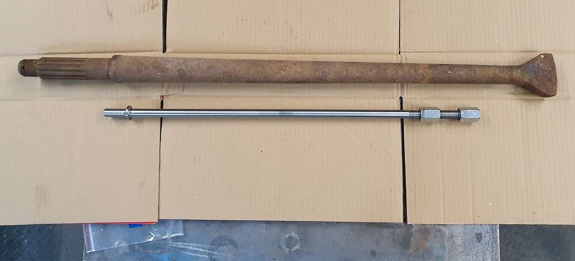
I wanted to make it out of some reasonably decent steel but wasn’t prepared to buy anything as that is out of the question at the mo. A friend of mine donated me 6 VW beetle half shafts some time ago, somewhat overkill but they were free and I had an empty builders bucket that really needed filling with chips and swarf!

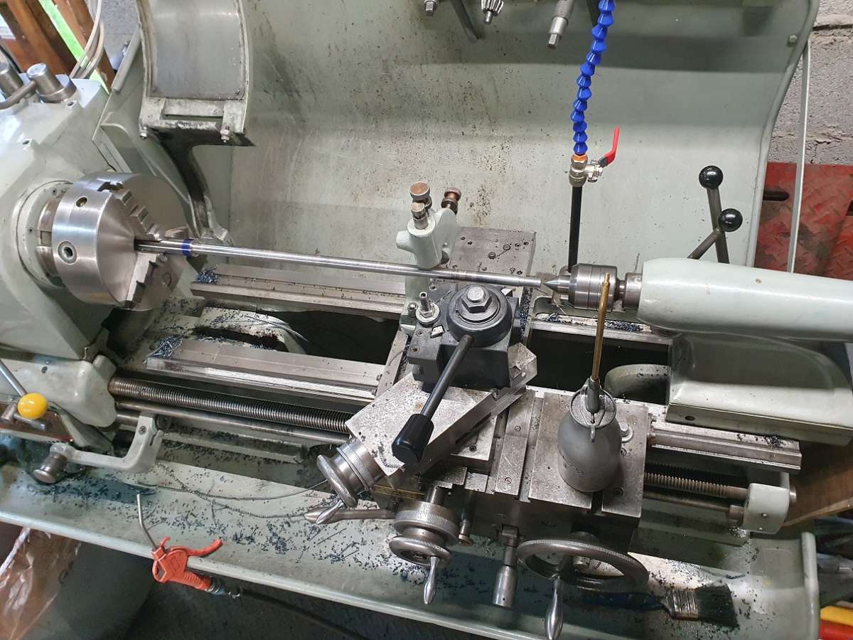
As you can see, it will just fit in the lathe with the tailstock at it’s limit but at least I could turn the whole thing without re chucking.
I forgot to take a pic of before machining but there is at least 1 bucket of chips and noodles already! I took this while I released everything for a bit and let it cool down. I’ve No idea what the steel is but it is dam hard and despite trying every type of insert I had, virtually every speed and feed rate as well as depth of cut it was really difficult to get anything other than noodles from it with anything over a 4 – 5 thou depth of cut so I gave up messing about and just let it noodle and used a small stick of wood to break them into large chips as they came off.
Once I’d machined it I put the thread cutting tool onto the tool post which was when the realisation that a Colchester Student Mk 1 and a bit can not cut a 1.75mm pitch hit me. This is pretty tough stuff so cutting with a die wont be easy.
I tried with my old Sealey split die set – not sure what I was expecting but to be fair to it, it did cut the short thread then promptly gave up after only a turn and a bit on the top longer section. I had cut the major dia to the lower end of spec to give it a fighting chance and with the die opened out so only cutting part of the thread it point blank refused to cut any more. I did try to dress the cutting edges with a fine diamond burr in the Dremel and although it did do about another rotation it decided enough was enough and split in half (most certainly a result of me fiddling with it with the Dremel).
I ordered a proper Presto split die for my larger 1 5/16 holder and hay ‘presto’ the thread was cut easy enough.
Eventually, after more passes than I care to remember and having to get the traveling steady out and filling a large bucket with it’s remains and having to get a new die this thing appeared out of what it’s next to.

The flattened end of the drive shaft is ridiculously hard, when roughing out I lost concentration when turning back up towards it and let it run past my sharpie mark into the area where is begins to get really hard and the WNMG 09 insert exploded! I tried several things like hacksaw’s etc to mark it but all it did was blunt them without making anything other than a visible polished mark.

I still need to shape the shoulder in the spindle but that is going to wait until I have the little thrust bearing so I can make sure the clearance is correct.

Once tested then I will pin the top barrel nut to the bar. I thought I’d use barrel nuts to make it easier to get spanners on over the top of the machine, less angle critical.
That’ll do for now, I’ve got a little progress on the table too so will update when it’s done. 👍
Cheers all! 🍻
9 October 2024 at 05:22 #758090 Michael GilliganParticipant@michaelgilligan61133
Spectacular work and dedication there, Taf
You deserve this to be a roaring success !
MichaelG.
10 October 2024 at 18:18 #758550 Taf_PembsParticipant@taf_pembs
Afternoon all !
So this captive drawbar thing..
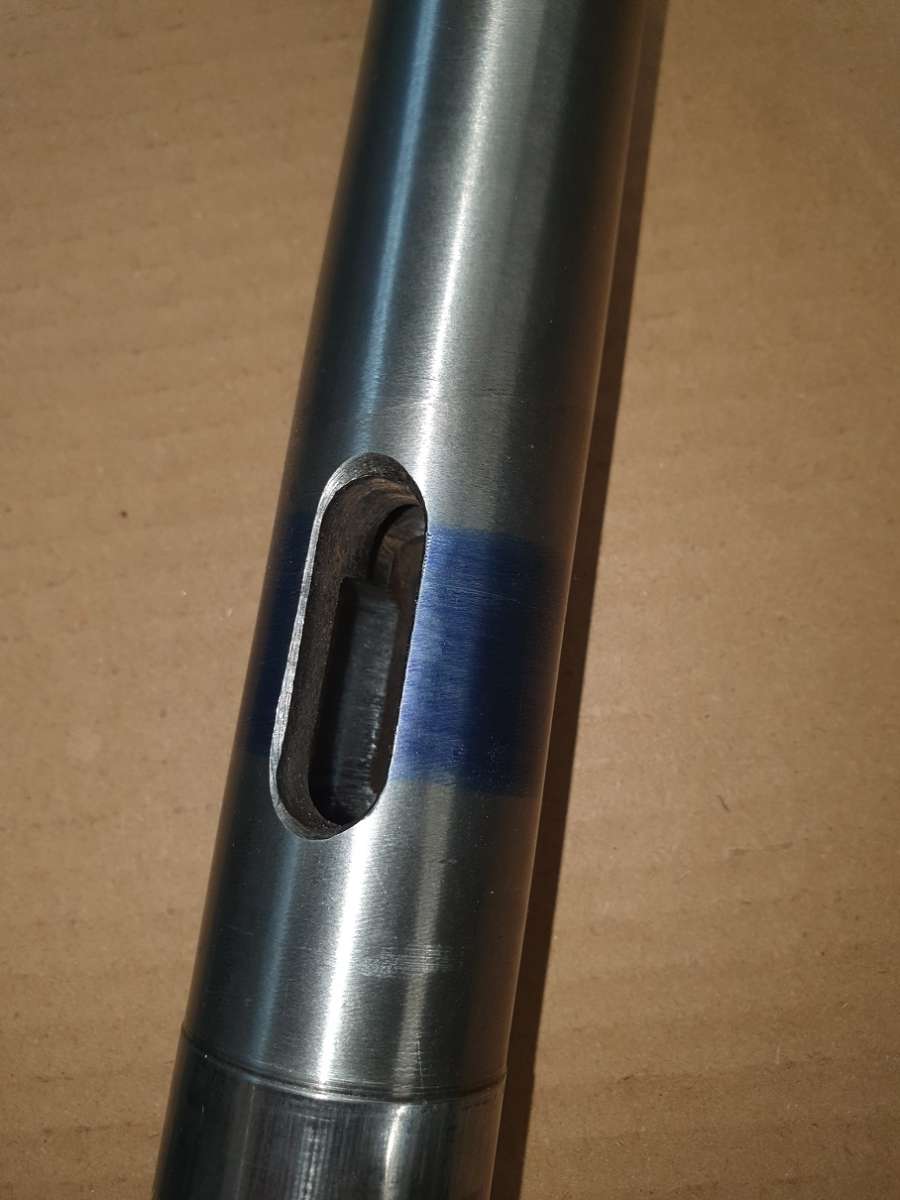
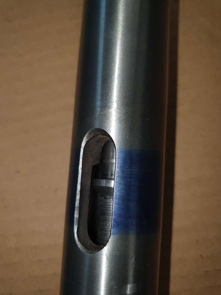
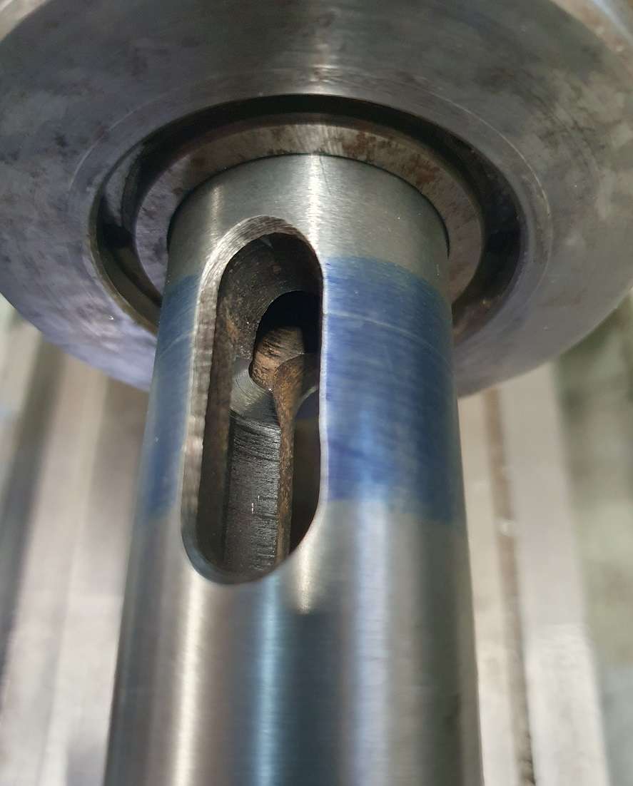
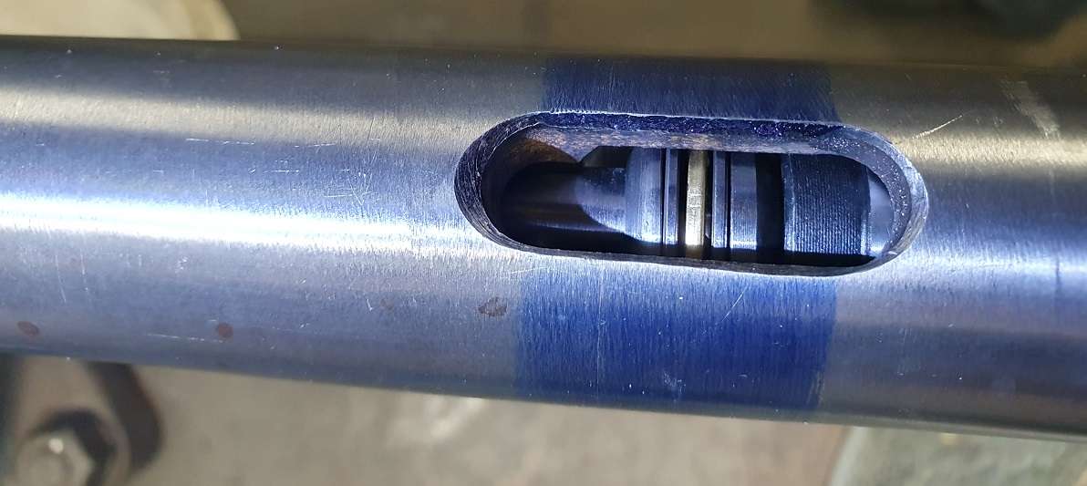
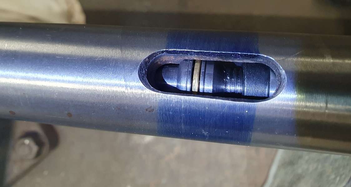
When cleaning up the inside of the spindle in the area needed for the drawbar to stop and eject the arbour I had to go about 4 – 5mm into the ‘meat’ where the internal bore reduces to just over 12mm. Firstly to get the required clearance for the drawbar to work and also to provide a shoulder for it to seat on when ejecting. I decided that the internal shoulder of the spindle was going to have a 30deg taper and a small radius at the outer edge to prevent any sharp edges and create any stress points. So I stuck it back in the lathe collet chuck and again with a ludicrous stick out on a 12mm boring bar carefully cut it. It was trickier than I though to do the small outer radius than expected as you can only see when either of the tool ejection slots come round.. got there though. Difficult to see in this pic with the light but it is there.

Then just made a corresponding washer to sit above the thrust bearing.

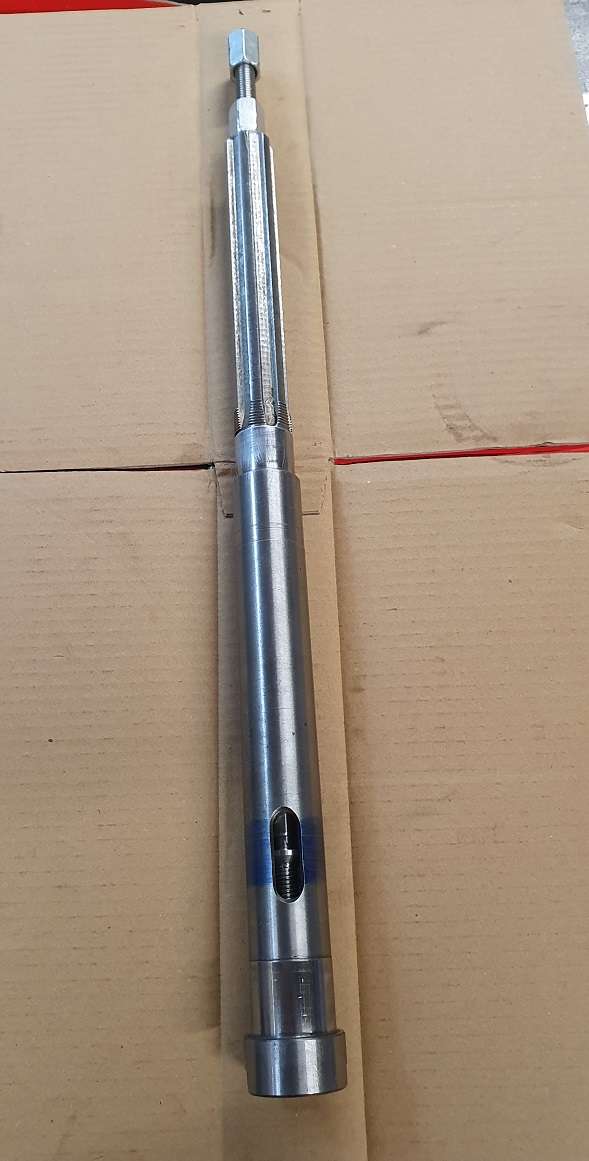
And here it is with an arbour in the spindle and fully tightened.

And then this is with the drawbar unscrewed to the eject position

I thought there is no point being gentle with it, it is either man enough for the job or it isn’t so I put the spindle splines in the vice soft jaws as so..

I put an arbour in it and horsed it up significantly tighter than you should ever need to and then tried the ‘tapping’ method to remove it. It had a fair few pretty enthusiastic blows but refused to come out.. no probs I thought, I can just put a little gentle heat around it and it’ll come out.
But.. before that I re checked the tightness of the drawbar just in case I had loosened it with the blows and if anything made it even tighter – oops, and as I’ve not pinned the top nut to the shaft yet, I just lightly locked the nuts together and gave it a try to see if the drawbar would eject it.
I really wasn’t expecting much and already had the hot air gun out but with surprisingly little turning effort – not even supporting the spanner at the nut, just a 1 handed turn – it popped straight out! 😲 It only …… works!!
The biggest frustration though is the new MT3 ER32 collet chuck I bought has the drawbar thread a fair bit off true the the axis of the chuck making it really difficult to insert the drawbar. The bore of the spindle is only a shade over 12mm, the drawbar is 12mm so the thread angle in the collet chuck means it goes pretty difficult to turn after only a little over 1 turn. The drawbar has to be wound in by spanner.
Doesn’t show up that well in this pic but with the drawbar held in the vice the collet chuck oscillates round when threading it on to it (got a small video somewhere I might put up).

I was a little surprised at this, being from Arc Euro, everything else about it is excellent, run out, nut threads, finish quality etc and being well hardened there isn’t much chance of correcting in any way. I expect with a less stiff drawbar there would be enough flex in it to make this no problem at all. The others are all bob on so we’ll manage.
Anyway, that’s enough rambling.. I need to get sorting the pics of the table fitment etc.
Cheers all..!!
Taf.
22 October 2024 at 11:09 #760603 Taf_PembsParticipant@taf_pembs
Good morning all..!
Some more progress..
So with that little extra out of the way it was time to start on the table.
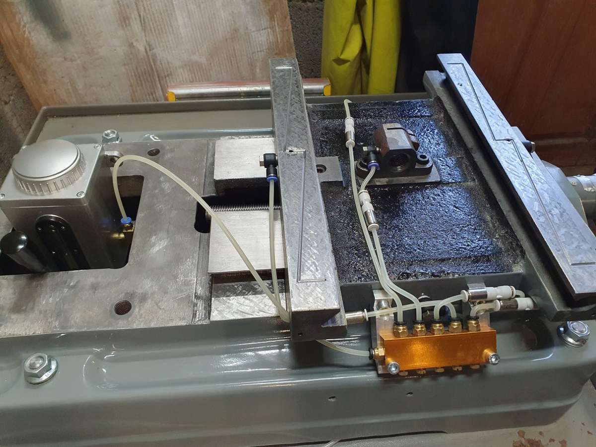
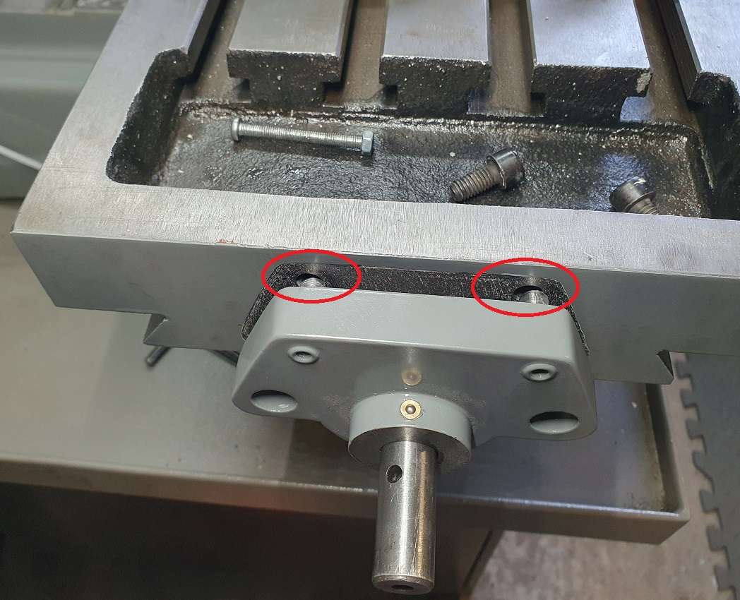
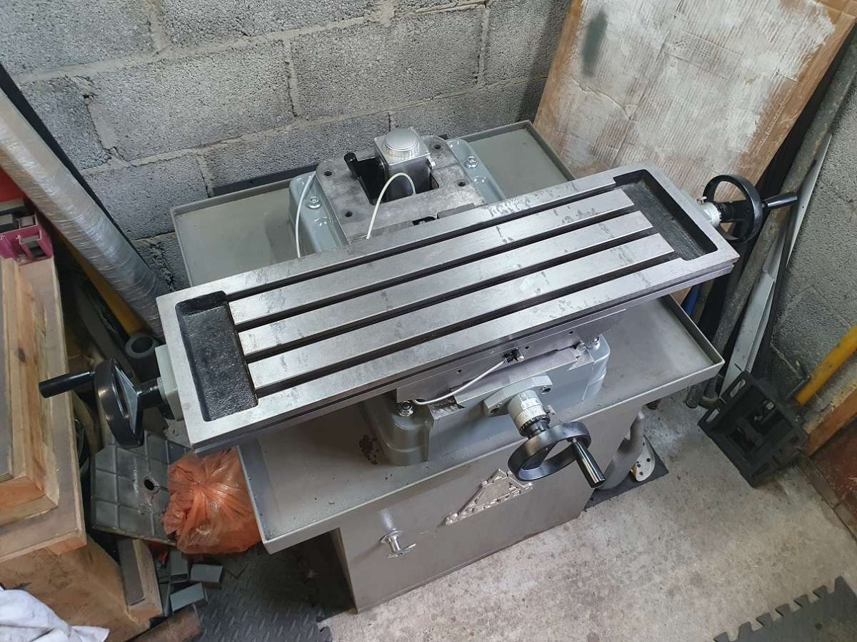
I fitted the saddle, after fighting the mounting angle of the Y nut for another age, I had wanted to try and drill and ream for a dowel pin as well as the bolt to help locate it but just not really possible without drilling through the table mounting dovetail so just live with it. I’ve already shown the mounting for the lube system so here is a pic of the saddle and the beginnings of the lube system. No protection for the pipework added yet as I wanted to prove everything first before finishing.. good job as it turns out!

The tubing bends were formed just using a heat gun with a small nozzle and heating just enough for the tube to easily bend without kinking (it goes fairly clear just as it’s at the right temp). I have also fitted check valves to all the lines, this will prevent flow back and emptying of any of the lines so each pull of the pump will deliver oil to each port rather than just the lowest ones and fill the lines of the higher ones.
I was wondering how well the pump would work with that many check valves but after fitting and having a fiddle with the metering valves under the ports on the distribution block it works perfectly and even if left for a couple of days it still delivers the same amount of oil to each oil point so another success!
Thinking that was that I added the ‘protective’ wound wire sleeves to the pipework and thought it was done.🙄

Time to fit the table.
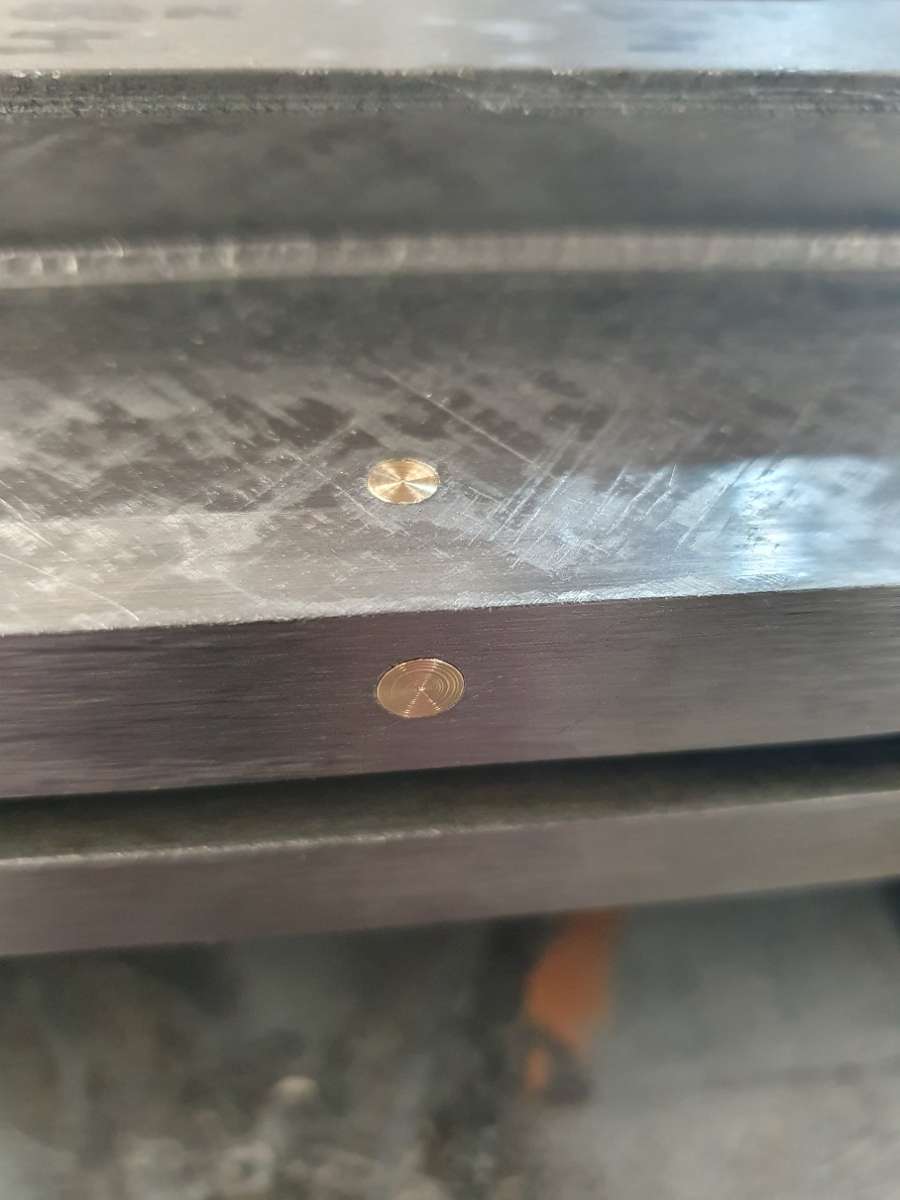
Firstly turn down some brass to plug the original button oiler holes, here is rough fitting, I dressed them a little after to tidy them up.

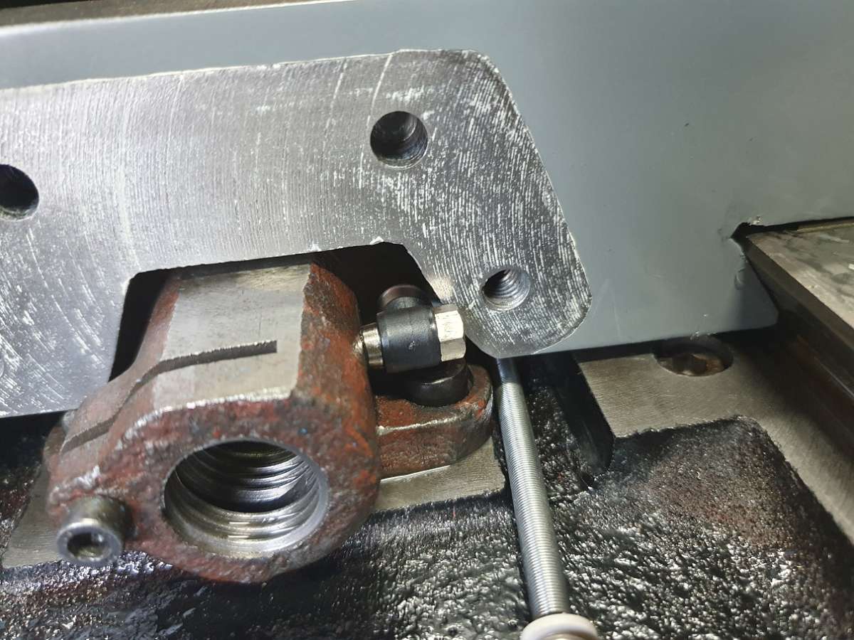
On trying to then fit the table I learnt something.. my measuring can be utter rubbish!!

I could have sworn that when I measured and checked, the table cleared the oil fitting! Ah well.
As it’s not really possible to remove the oil fitting and re fit after the table was in place the only option was to trim a little form the table so that’s what happened – forgot to get a pic but you can see it is just a little form 1 side.
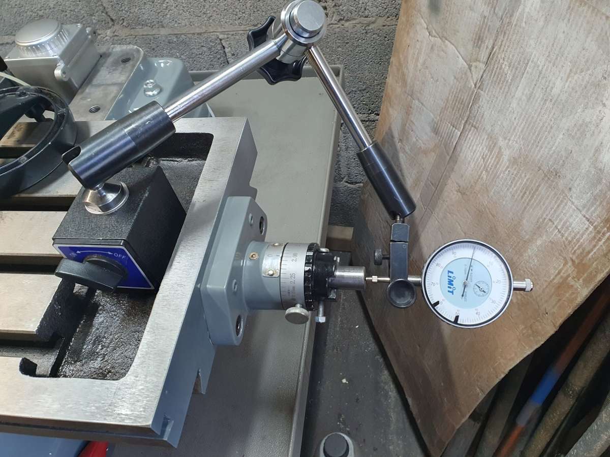
With the table mounted without the leadscrew mounts on either end and the gib roughly adjusted I fitted the lead screw and threaded it to its halfway point so it was just nicely balanced in the nut.
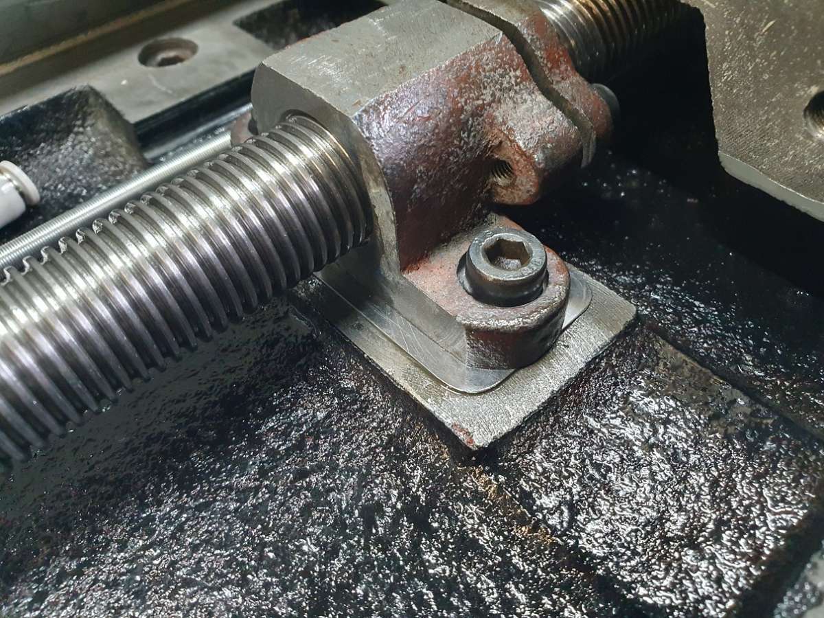
I then fitted the main R/H lead screw mount to the table and carefully slid the table towards the screw to see the alignment.
A note before this that prior to disassembly the X lead screw was always on the stiff side even with the gib slackened off. Not excessive but obviously not right.
So sliding the table to the lead screw showed that there was a little lateral misalignment. There was also a little vertical misalignment so I added a 0.5mm shim under the nut to see the effect.

This sorted the vertical misalignment but this was a mistake as I soon realised.h

I did mount it to see the effect (and compare to prior strip down). It was pretty stiff, if anything worse than before.
I tried to slacken the nut mounting bolts and adjust the position / angle of the nut but nothing really made much difference.
I then realised that the lead screw be resting at it’s lowest point in the nut not centrally as it would be in use so promptly removed the shim.
Doing this I noticed that the counter bores in the X nut bolt holes weren’t counterbored, they were just drilled so no amount of adjusting was going to make any difference, the socket cap bolt heads were always going to re centre in the drill tip taper. I sorted this and set about trying to adjust the position of the nut so I could get alignment of the lead screw, the nut and its table mounts.
A fair few hours later and with the leadscrew nut now facing the opposite direction (I had refitted it as it came apart) and having to re do the lube pipework so the feed for the x nut could then come from near the front side of the distribution block, I had alignment! I even had a brew to celebrate!
Oddly enough , even with the gib snugged right up the hand wheel / table movement was lovely and smooth.
Phew!
22 October 2024 at 11:17 #760604 Michael GilliganParticipant@michaelgilligan61133
That will be a very nice machine when you’ve finished fettling it.
MichaelG.
22 October 2024 at 11:19 #760605 Taf_PembsParticipant@taf_pembs
Then time to address the backlash (the nut shouldn’t be a problem as thanks to MG’s chunk of bronze there is a new one partly made 😁🍻) but the basic thrust bearings at the table needed addressing.

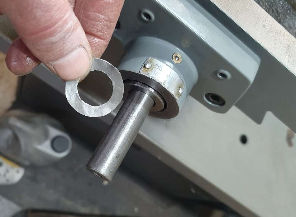
I genuinely cant remember what is measured but it was around .5 mm just at the thrust bearing ( I did write it down somewhere) so I made a really poor effort of hand cutting some shim to pack behind one thrust bearing.

Well.. it worked! it was a smidge tight but once used a little it was fine (just the rough edges flattening out).

And there we are.. a little tidying and supporting of the oil lines and jobs a good (or good enough) ‘un !
22 October 2024 at 11:20 #760606 Taf_PembsParticipant@taf_pembs
That will be a very nice machine when you’ve finished fettling it.
MichaelG.
Time will Tell Michael, time will tell. I certainly hope so! 🍻
22 October 2024 at 12:13 #760617 Taf_PembsParticipant@taf_pembs
Spindle assembly.
I decided that I would rather mount the flat hub seal ‘rubber side up’ so the upward facing lip would help deflect any debris away from the seal face than allow it to fall into it ( I believe the correct way anyway!). Unfortunately this way up the seal didn’t quite touch the quill sleeve face (which wasn’t that smooth anyway) so I chucked it up in the 4 jaw and removed about 0.5mm from the upper bearing cup seat which as it turned out is what it took to clean it up properly! I did try to measure the gap as best I could and work out the required amount to remove as the seal face is a 45 dig angle. I had worked out a little more than that but doing a couple of test fits showed that was enough for a light contact. I also dressed the face that the seal would bare on.

Then time to assemble.. best have a tidy and clean up.

I greased up the bearings, I wasn’t too worried about putting a little too much grease in the bearings as being open taper bearings they would soon push out the excess so I assembled, lightly nipped the bearings and gave it a run to settle the grease so I could remove most of the excess.
Cordless drills and a wee clamp on the trigger are pretty useful!

Then strip to assess / clean up excess grease, re assemble and repeat until everything was good.

Previously I mentioned that the upper bearing was extremely tight on the spindle and almost impossible to adjust so I dressed the spindle to allow the bearing to just about slide on it. My biggest mistake was using the old not new bearing to check it as the new bearing wasn’t as snug a fit. What a plonker!
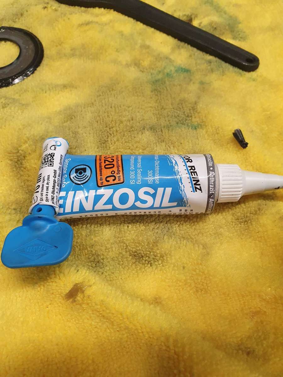
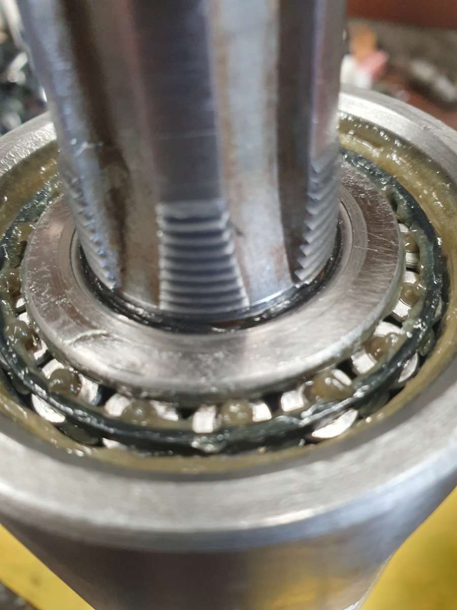
The down side of this was that once the bearing warmed up a little the fit wasn’t quite tight enough so to prevent any possibility of it spinning on the shaft so I rubbed a tiny bit of Reinzosil (a gasket sealing compound I have used quite a lot in the past as it is a flexible bond that doesn’t seem to behave like the usual sealers, more like a setting hylomar) onto the inner surface of the bearing and also onto the shaft. It was barely visible but enough to create a flexible bond. I then assembled the spindle to about the correct preload and left it to cure.

It worked a treat, the preload can be adjusted but there is no chance of the bearing spinning on the shaft. You can just see the excess at the bottom of the threads in the pic below, which looks like more than I put on!
Not ideal but works and the runout hasn’t changed from … nothing.

If I need to remove it it will be easy enough to push the shaft through the earing, no heat required.
So it all looks like this again now and runs smooth with very little heat build up round the bearings.

I’m in the process of sorting the gear head now, addressing the few issues I found when I stripped and then later on assessed it properly.
Cheers all..! 🍻h
22 October 2024 at 14:06 #760635 Nigel BennettParticipant@nigelbennett69913
Well you’ve got past the 30,000 words on this subject now, Taf – and what an excellent treatise it is on how to do it. (I’m rather glad my Lux milling machine (now 20+ years old) has the ISO 30 spindle, so I don’t have the problem of ejecting things. It’s a shame they don’t still offer it as an alternative.)
Many thanks for taking the trouble to record all the progress; I’ve now got a brilliant manual on what’s inside my machine when I need to take it to bits to mend it! I’ve actually copied all this thread into a Word document so I can read through it at my leisure. 230 pages and counting…
Hopefully it won’t be too long before yours is all back together again and cutting metal. Accurately…
Thanks again!
23 October 2024 at 18:53 #760830 Taf_PembsParticipant@taf_pembs
Cheers Nigel!
30,000 words!! are you sure, I’ve never written that much in my life before 🤣
It most certainly isn’t a how to, just how I’ve gone about it. I’m sure doing it again there would be many changes (and less boo boo’s!).
Glad it may be of some use 👍🍻
24 October 2024 at 08:55 #760888 Taf_PembsParticipant@taf_pembs
Mornin’ all..!
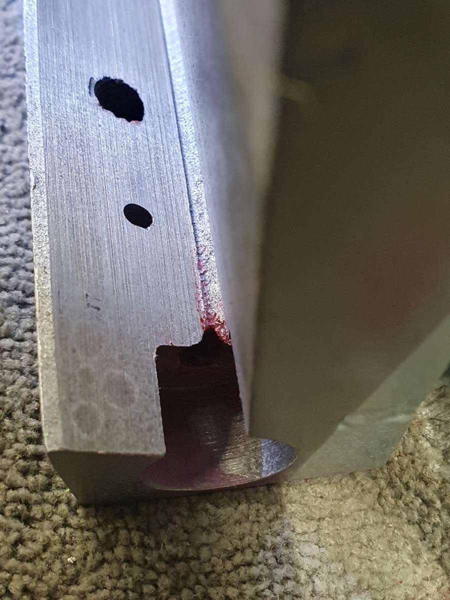
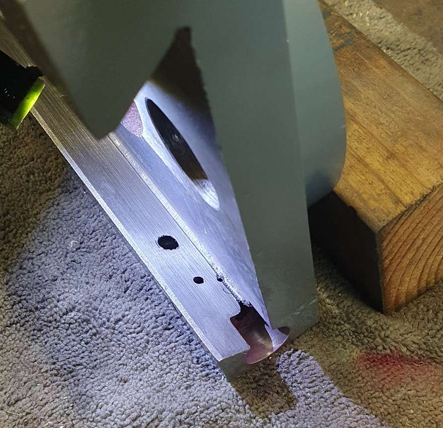
Before I start on the gear head assembly I thought it best to address something else I found during properly assessing everything after stripping and cleaning. The vertical saddle. Dreadfully poor manufacture resulting in a crack.
I doubt very much it’s going to be a problem as I expect it’s been there for a long time due to where it is but the fact that it’s there, and we all know what happens to cracks if they are left, it needs something doing.


Unfortunately this is the upper end of the column saddle and therefore has a pretty high outward pulling force due to the weight of the gearhead so any crack is a somewhat unwelcome visitor.
Out with the crack detection spray and try to get a better idea.

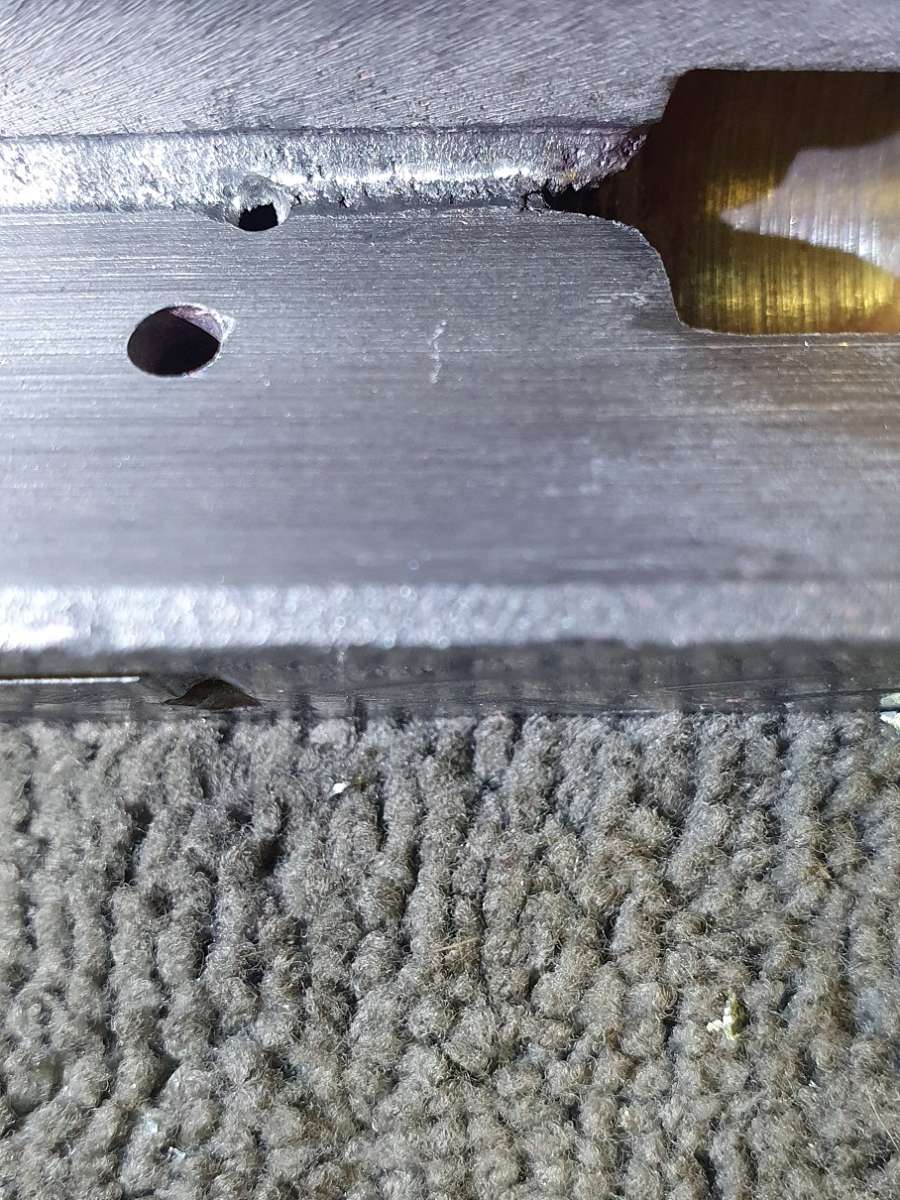
It was really difficult to get a reasonable pic of the result but by eye it was pretty obvious and clearly showed the extent of the crack.
So.. thanks to McDremel and the Tiny Spinny Things i.e. a very small diamond burr ball I just ground out the end of it so with a bit of luck it should not be able to propagate any further.
Almost there..

There we go..

That’s that job done. On to the gearhead.. I think!
24 October 2024 at 13:23 #760945 Taf_PembsParticipant@taf_pembs
To the gearhead….
Again, during the proper cleaning and inspecting there was 1 thing that stood out as pretty poor.
I have fitted all new bearings (SKF) and seals but the 1 / 2 / 3 speed gear cluster was rocking back and fore on the shaft due to a very loose keyway. Obviously the cluster has to have some free play to allow it to move up and down the shaft to select the required gear but not rotate a lot more than 1 tooth either way. The key should be 5mm square which would be a tight fit in the shaft and a sliding fit on the cluster yet the key was aprox 4.4mm wide (at it’s thickest point!) and well dented and burred over where it had been rocking (not the best key steel) and creating most of the noise I suspect!
Everything deburred and a new key fitted and it now behaves how it should.

There was nothing wrong with the Hi / Low range cluster, it slid nicely and barely any play so that stayed as is and everything back together.

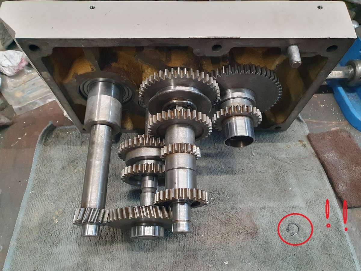
I spotted the circlip after looking at the photo which started the usual ‘where the hell did that come from’ murmurings (or is that swearing!). Once I went back to the workshop and looked, it was one of the old ones that had just got stuck to the cloth – then followed by the large sigh of relief!
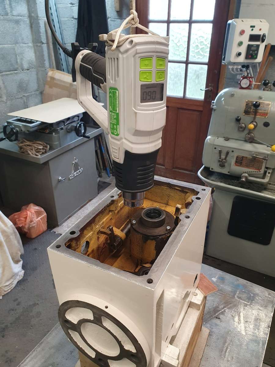
Time to put together and see how it is. I though I would try to warm up the main casting to around 50 deg to make assembly a little easier so not having to use to much force to get the bearings and shafts to come together.
It worked a treat!! It took a fair while and had to keep increasing the temp to get a decent temp in the casting.

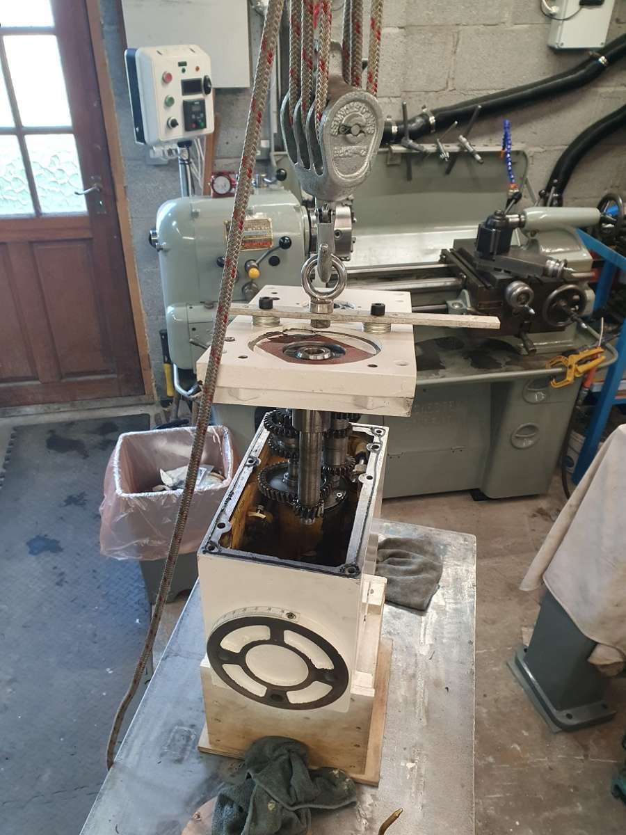
While that was doing it’s business I knocked up a way of lifting the top plate and gear cluster as it would be impossible to do with effectively 1 working hand, holding the weight of it and getting the selector arms located in the clusters etc.

Once together time to check everything.

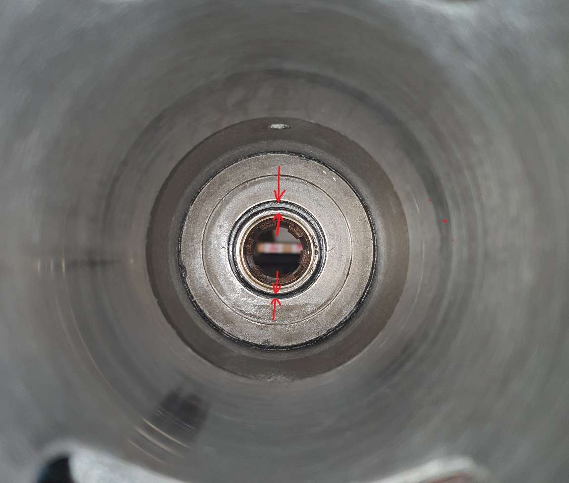
Spindle located in the splines to be able to rotate everything and checked all the gears etc. Everything seemed perfectly OK till I looked underneath and up the Quill sleeve.

The seals were being crushed on 1 side by the spindle drive. On closer inspection it was the seal housing plate that was off centre.

So stripped apart again, I slackened off the plate securing screws and tried to adjust it thinking it’s just down the the fact that the bore is slightly larger now due to fitting the liner but soon realised that it must have always been in this position as it was the only position that the screws could be inserted.

I decided to make a small collar to fit around the quill side register to make sure it was centralised to the bore and I knew exactly where the off cut from the liner was and it was just long enough to chuck up. This appeared out of it. It was a snug fit, I was worried it would split trying to push it on but no, went on OK and I used a little loctite 603 just in case.

Once that was fitted I could then elongate the mounting holes just enough to secure it. I also replaces the really crappy screws with some socket cap’s.


Once refitted it looked pretty good.

Re assemble again.
24 October 2024 at 14:03 #760962 Taf_PembsParticipant@taf_pembs
Hopefully final assembly.

Oh, I forgot to mention that I also added a couple of magnets into the casting –

With a bit of luck this should hold onto any ware material.
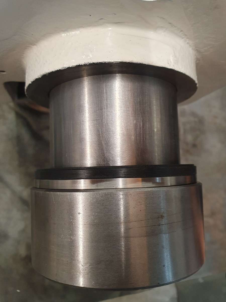
The Quill / Spindle assembly – it fits beautifully into the sleeve, I am still a little concerned that it may be a little too snug and once running the warmth of the bearings might make it a little stiff but I can always hone a little more out rather than over do it now.
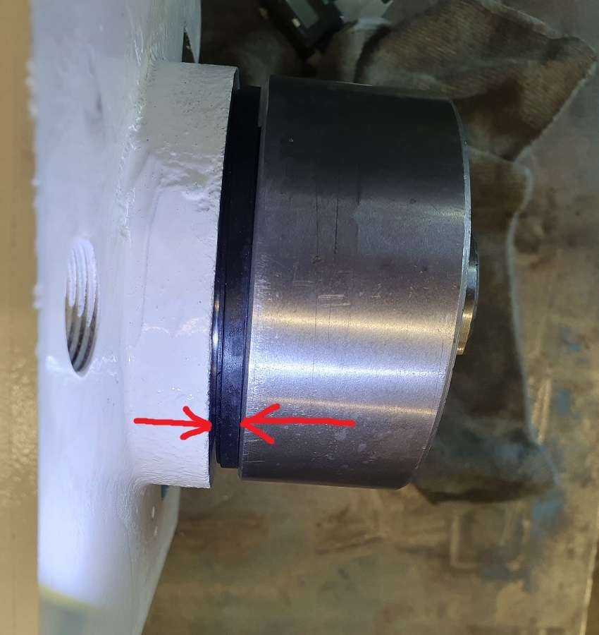
The biggest problem is that when fitting the liner I skimmed the bottom end including just enough of the casting to make it flat and smooth as was as rough as a badgers ar….. Well, this coupled with the thickness of the new hub seal on top of the spindle bearings and the very slightly thicker bearing nut means that the Spindle bearing nut now touches the top seal plate before the quill seats on it’s rubber cushion ring.. 🤬🙄
I thought there was enough clearance but didn’t allow for the aprox 2mm I had to take off the bottom of the quill sleeve face.

This photo is taken with it bottomed out on the upper seal housing. You can still see quill shaft past the rubber cushion.
The fix? Taught my young un (14 year old daughter) to use a lathe 😁
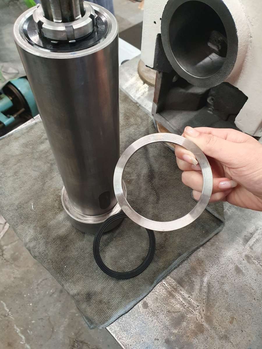
The only decent piece of stock I could find was an old spacer from the top of a rudder stock shaft – essentially a giant stainless washer, 6″ OD, 2″ id and 1/2″ thick. Once I set it up for her she used light cuts (couldn’t hold it well enough to rough it) to whittle it down to something useful. She did a cracking job with just a little supervision and guidance!!
A 4.5mm thick spacer.

And fitted, leaves 2.5mm clearance at the top. That rubber cant compress that much.

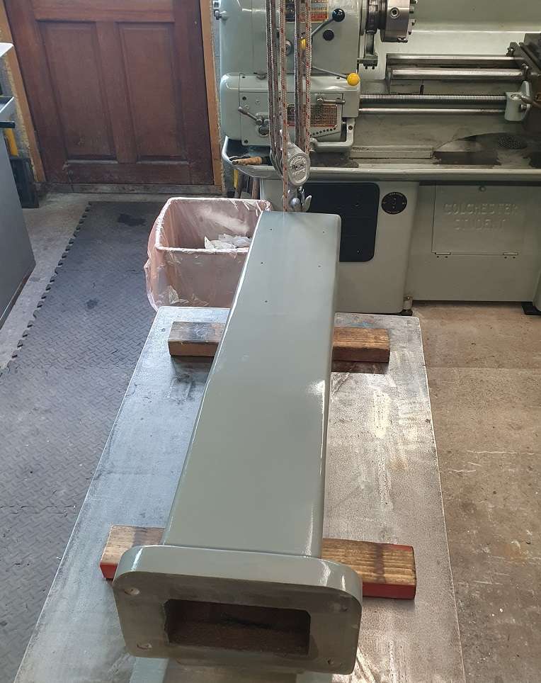
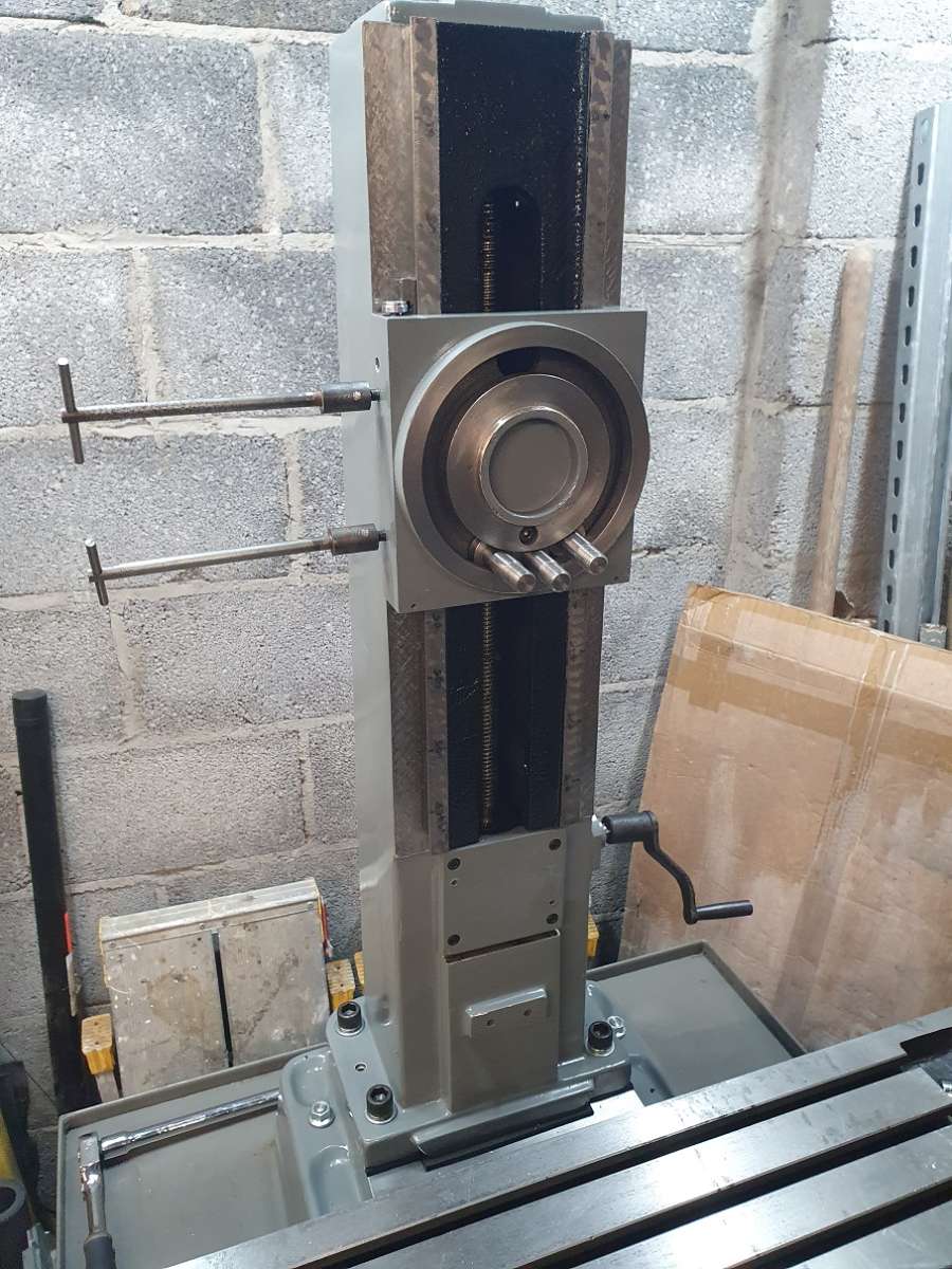
Next job.. Column up on the bench and set to getting ready to mount it on the base.
The SKC 57 resin is on order from M.Buttkereit who were very helpful and it wasn’t as expensive as I expected, about 20 quid for a 0.2kg pot.

There, Column on the table ready to get going.
That’ll do for a bit,
Cheers all..!!
🍻
25 November 2024 at 08:52 #766672 Taf_PembsParticipant@taf_pembs
Mornin’ All! Been a while, had a fair bit going on.
This column then. Obviously need to prepare it for mounting and ‘resining’ if that’s a word!
I would like to be able to separate the column if required in the future so after proper cleaning I decided to apply some silicone release agent and buff it back (and repeat!) to the bottom of the column. With a bit of luck it wont physically bond.
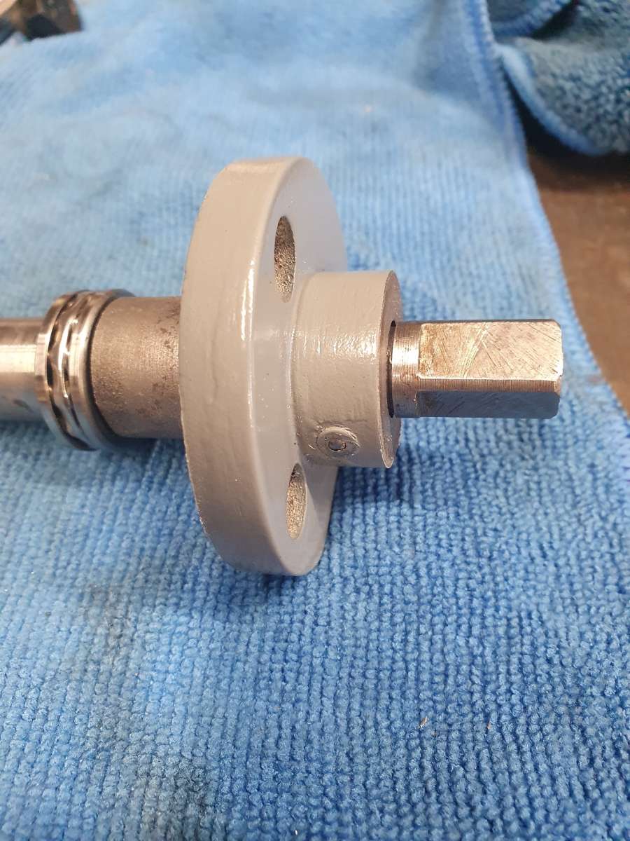
Next was to address something not really necessary but annoyed me a little so was being done. The manual crank pinion for the Z axis was retained by a circlip just rubbing against the casting so I wanted a washer between. You can just make out the groove in the pinion here

So I turned a little off the face and added a washer.

Assembled – The only thin washer I could find to suit was this partly de zincified bronze one but now it’s painted on the outside you’ll never know!

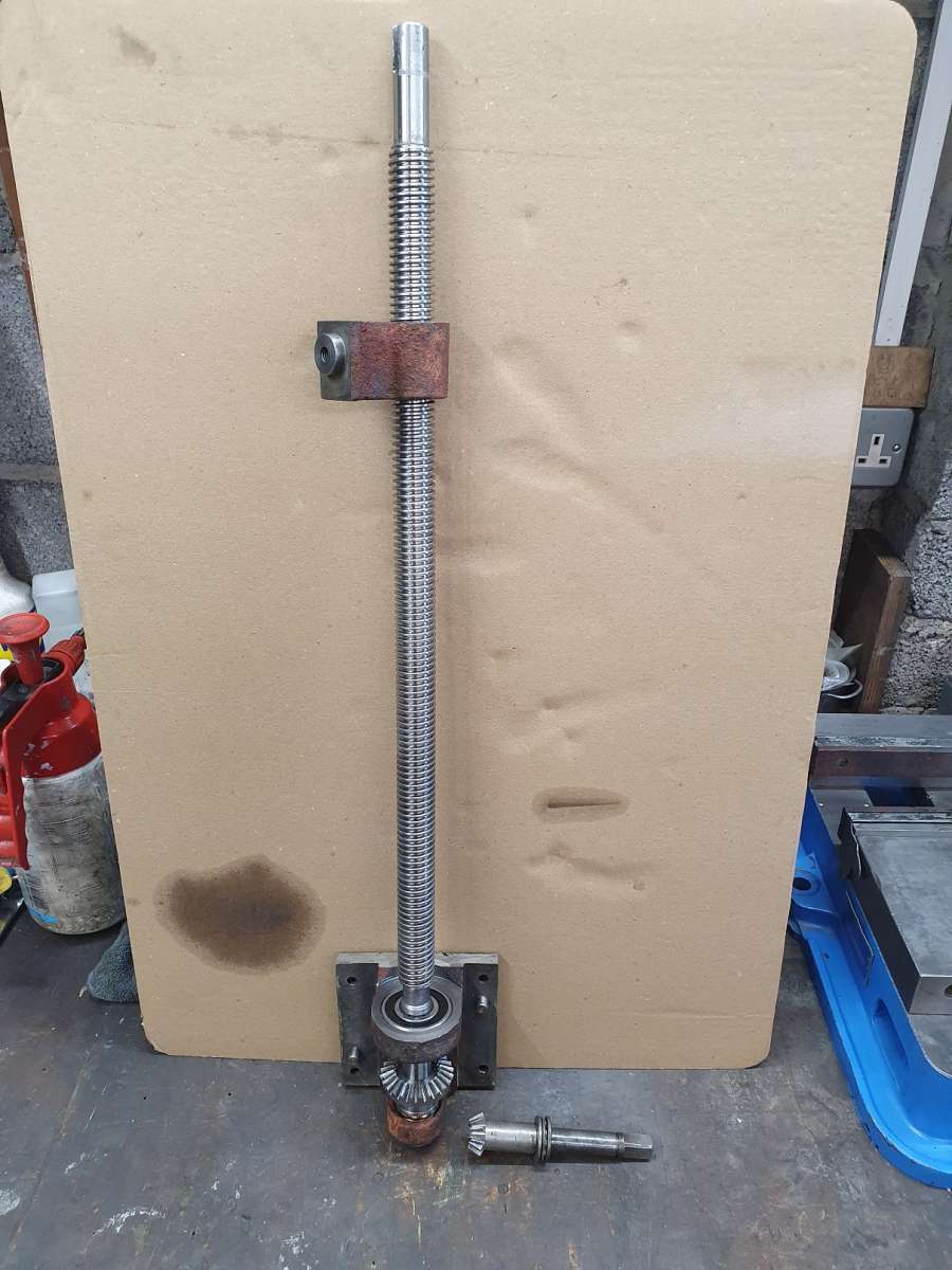
Cleaned up ready the Z lead screw assembly ready for lube and install.

” There’s always time for lube!! ”

All going swimmingly as they say..
More in a mo 🍻
25 November 2024 at 09:37 #766682 Taf_PembsParticipant@taf_pembs
On to the Base.
A real good clean up then set to it with some emery and cleaned again, I want the resin to proper bond to this.

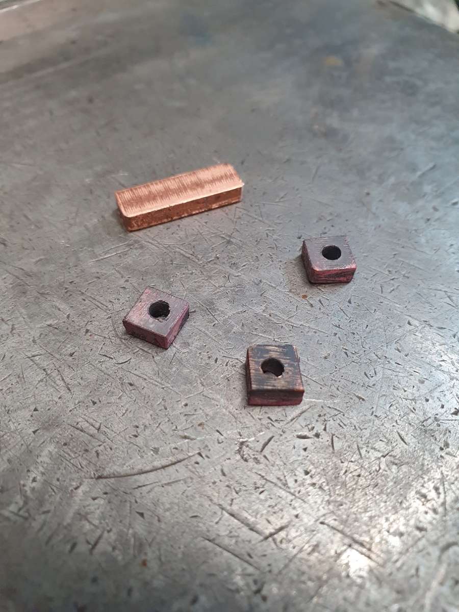
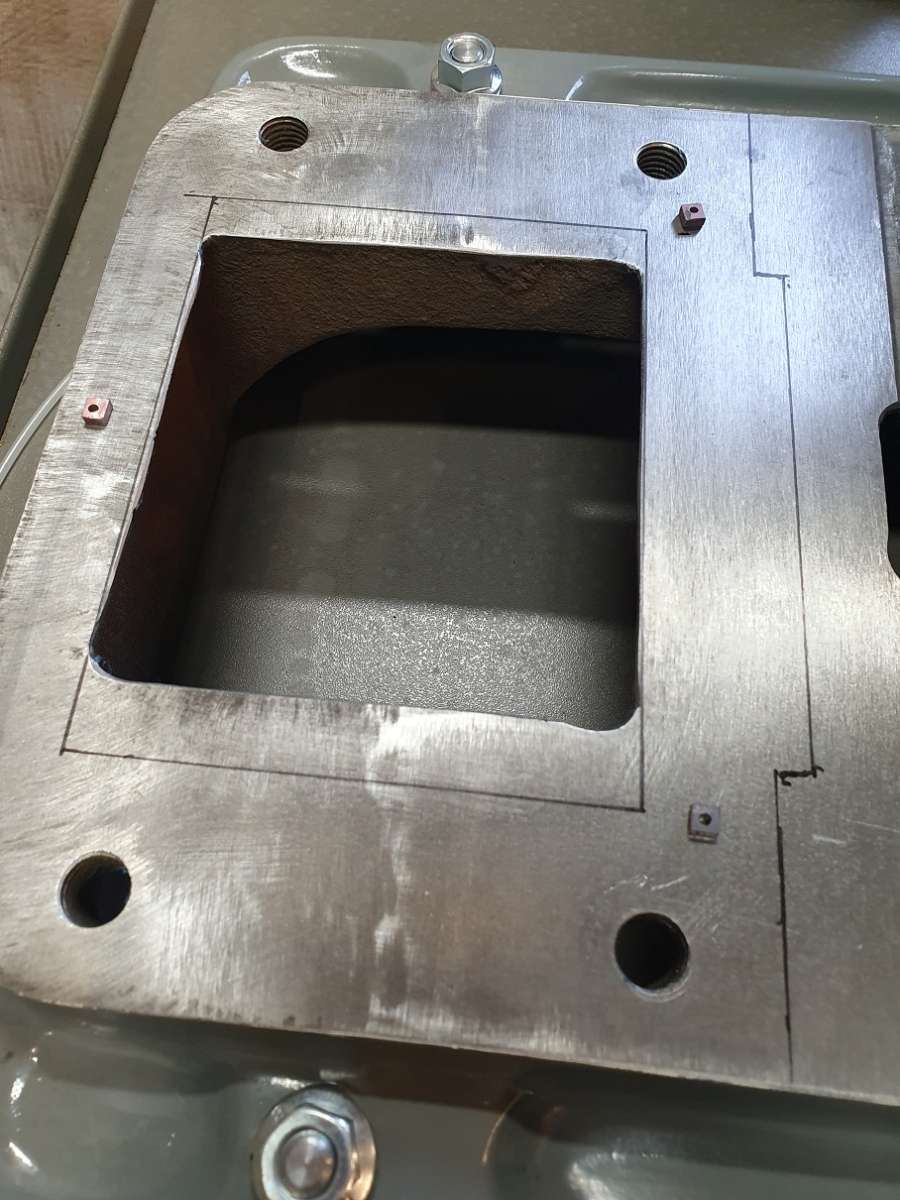
Then to make some copper spacers for mounting the column. I already did a test fit a bit ago just experimenting with different spacers to see how they squashed and this was the result. Roughly 6mm square, 3 and a bit mm thick (I was aiming for about 3 1/2 but with a hacksaw it’s near enough), 3mm hole in the middle to aid squash annealed copper pads.

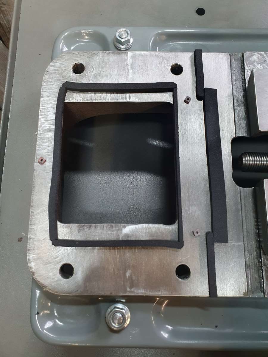
Then work out that actual contacting face area between the column and the base – turns out it isn’t as much as it really could be. I placed the copper pads to get a rough idea where to put them in relation to the support webbing underneath as some areas are pretty thin.

The plan then was to add self adhesive foam to the front edge and the internal edge to form the dam for the resin and use tape all round the rest of it.

I hope it holds up!
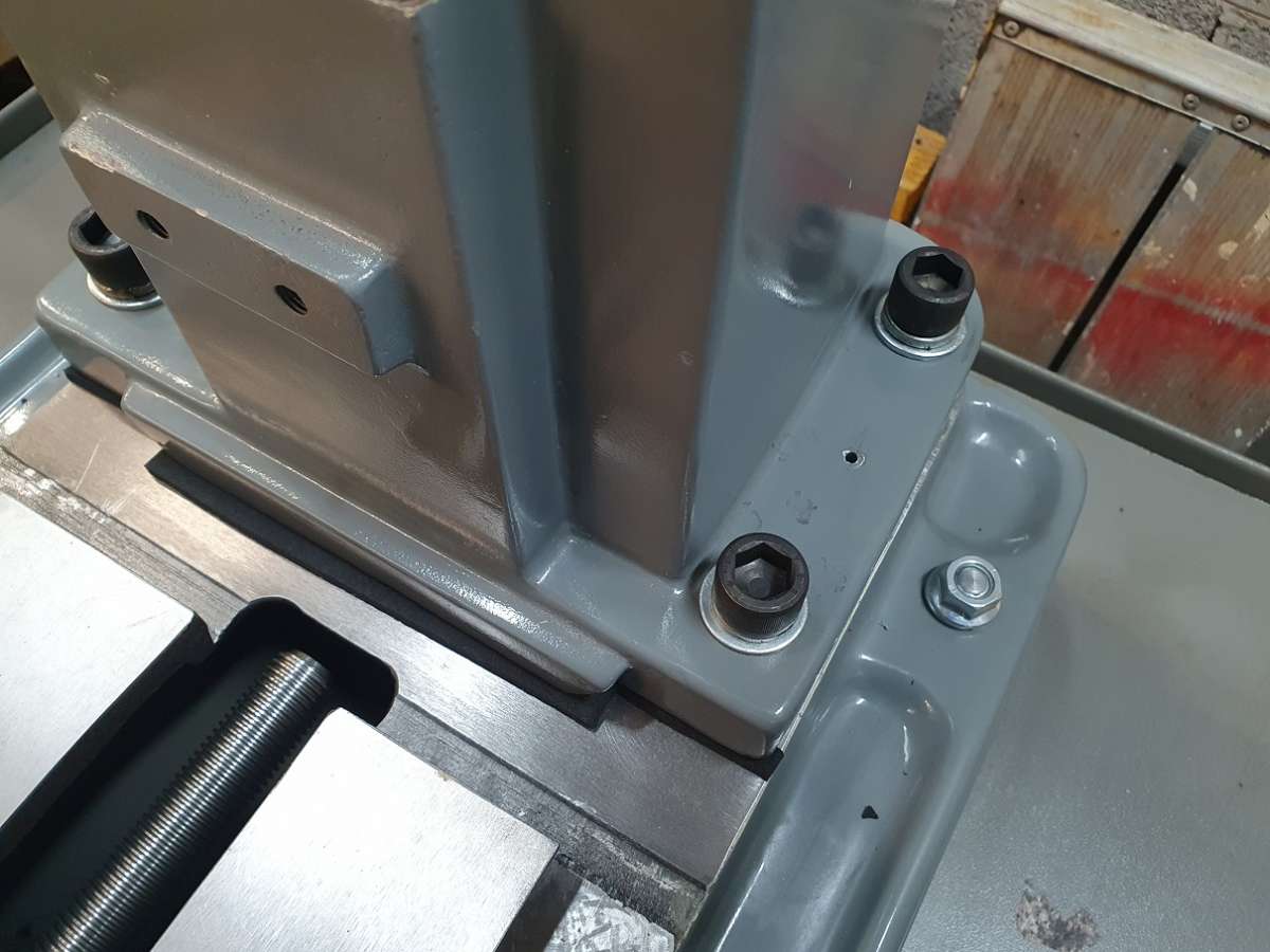
Just this weekend with a bit of help I’ve now got the column mounted – here showing the resin injection hole, a 7mm hole that I then ran a small step drill in a little to form an extra couple of rings that the nozzle with seal against when pushed in.

here showing the vent hole.

The plan is that once the resin shows at the vent hole and with the injection cartridge still in the hole I will just prick tape at the upper side of the gap in a few places to make sure the resin is all the way round and to all the edges, can then re tape.
Here is the gap.

A rough alignment then to get it somewhere near while I start to add the z saddle and gear head etc.


And that’s as far as I’ve got. This one handed lark really does slow you down!
On a little of a set back, unfortunately Martin Buttkereit contacted me to apologise for the delay getting the SKC Resin and had some bad news.
SKC Gleittechnik in Germany would not ship such a small quantity for some unknown reason (they said they would only ship a pallet!) so he had to cancel the order.
Martin’s solution was to give me full refund and offer to send me, FOC, some out of date resin. He explained that the biggest issue with the out of date stuff is that the solids separate out so the procedure is to spend a long time mixing it, then leave it for a day as the amount of mixing required heats it up so will cure far to quickly. After it’s properly cooled, then mix normally, add hardener and use. I explained I still wanted the injection cartridges and mixing paddle etc but he still gave me a full refund.
A very large parcel then turned up from him with 4 pots of resin and appropriate hardener pots, mixing attachment and a bag of injection cartridges!
Thank you very much Martin if you do look in here, it is greatly appreciated!
I’ve arranged with an old friend of mine that we will hopefully be attempting the job at the weekend (cant do it on my own plus then I’ve got someone to blame! 😁).
First job is to do a test mix with 1 of the pots, leave, then mix properly, get it in an injection cartridge and see what the working time is as I’ve found old stuff tends to go off either very quickly or very slowly so best find out first.
Fingers crossed all all goes well. That leaves me this week (with a bit of help) to get the gear head, motor etc mounted and the column trued up as best I can.. out with all the indicators and straits and start tweaking.
It’ll be interesting just how much the copper compresses with all the load on it.
Cheers for now! 👍🍻
25 November 2024 at 18:04 #766740Howard Lewis
Participant@howardlewis46836When you’ve finally completed this is going to be SOME machine; one, if not the of the best in the world!
Congratulations.
Howard
25 November 2024 at 19:46 #766763 Taf_PembsParticipant@taf_pembs
Ahh but Howard, I have to complete it yet!!
Cheers, I hope it is just a decent usable machine.
I’m looking forward to trying a fly cut on some aluminium which is what started this whole mission in the first place, it’s been a long time coming and there is plenty of room for things to go wonky yet. If I ever get these surgery’s I’m waiting for then the next one should only take a couple of months instead of a couple of years!
🍻
26 November 2024 at 08:28 #766794John MC
Participant@johnmc39344I’ve been following this thread with great interest having a very similar “Cormak” version of the machine. Haven’t gone to the lengths that Taf_P has had to do to correct errors, fortunately. I started a thread but there seemed little interest so haven’t added to it.
Assuming the manufacture of these machines is accurate the problem is that they are poorly proportioned. The head is far too big and heavy. The vertical column is far too flimsy. Just 4 bolts to hold it to the base. The footprint of the column is too small. In an ideal world the base and column would be one piece. When using the machine with the head well up the column the lack of stiffness is noticeable compared with the head near the bottom of the column. The column structure is this type of machines Achilles heal. When I sorted out my machine I made a new spindle and fitted it in to a shortened quill that moved the cutter some 56mm closer to the head (and closer to the bearing carrying the cutter load). This meant that I could keep the head lower down the column.
I fitted two long steel bars up through the column to the pull the it down on to the base in the hope that would improve the all important stiffness of the structure. I have further ideas for additional stiffening of the column.
The column needs to make metal to metal contact with the base. Introducing a layer of epoxy resin between is going to reducing the stiffness of an already inadequate joint therefore introducing flexibility where its not needed. I would urge you to go for a metal to metal joint. You have done some excellent work elsewhere with a scraper, use those skills to fit the column.
-
AuthorPosts
- Please log in to reply to this topic. Registering is free and easy using the links on the menu at the top of this page.
Latest Replies
Home › Forums › Manual machine tools › Topics
-
- Topic
- Voices
- Posts
- Last Post
-
-
Firth Valve Gear
Started by:
Andy Stopford in: Traction engines
- 8
- 16
-
1 July 2025 at 09:12
SillyOldDuffer
-
2 Machine lights
Started by:
modeng2000 in: Workshop Tools and Tooling
- 2
- 6
-
1 July 2025 at 08:57
Dalboy
-
Request for a Slot to be Milled in a Shaft
Started by:
James Alford in: Help and Assistance! (Offered or Wanted)
- 8
- 14
-
1 July 2025 at 08:50
not done it yet
-
IME Watchmakers lathe
Started by:
Greensands in: Manual machine tools
- 5
- 6
-
1 July 2025 at 08:26
SillyOldDuffer
-
New member looking for help
Started by:
 manfromthemist
in: Introduce Yourself – New members start here!
- 11
- 24
-
1 July 2025 at 08:19
Juddy
-
M type top slide conversion??
Started by:
jimmyjaffa in: Beginners questions
- 6
- 10
-
1 July 2025 at 07:20
 JasonB
-
Twin Engineering’s heavy mill/drill quill removal
Started by:
Martin of Wick in: Manual machine tools
- 6
- 7
-
30 June 2025 at 23:33
James Frankland
-
Bearing boxes for ball race
Started by:
Paul McDonough in: Beginners questions
- 8
- 14
-
30 June 2025 at 22:43
Stuart Smith 5
-
All things Beaver Mill
1
2
…
8
9
Started by:
Robert James 3 in: Manual machine tools
- 42
- 205
-
30 June 2025 at 21:14
Mark Rand
-
Wiring up a single phase AC motor with 4 wires
Started by:
ell81 in: Beginners questions
- 6
- 8
-
30 June 2025 at 19:49
Howard Lewis
-
New (old!) member
Started by:
iansoady in: Introduce Yourself – New members start here!
- 3
- 3
-
30 June 2025 at 19:30
Howard Lewis
-
Meddings MF4 Manual
Started by:
Richard Kirkman 1 in: Help and Assistance! (Offered or Wanted)
- 9
- 17
-
30 June 2025 at 16:11
Richard Kirkman 1
-
FreeCAD v1.0 tutorials
1
2
3
Started by:
 Michael Gilligan
in: CAD – Technical drawing & design
- 12
- 51
-
30 June 2025 at 15:40
Speedy Builder5
-
Boiler Design – issue 4765
1
2
…
7
8
Started by:
Charles Lamont in: Model Engineer & Workshop
- 26
- 178
-
30 June 2025 at 12:58
Paul Kemp
-
High strength 4mm steel?
1
2
Started by:
iansoady in: Materials
- 20
- 31
-
30 June 2025 at 10:55
JohnF
-
What Did You Do Today 2025
1
2
…
6
7
Started by:
 JasonB
in: The Tea Room
- 32
- 172
-
30 June 2025 at 07:37
Diogenes
-
cutting cams
Started by:
bricky in: Help and Assistance! (Offered or Wanted)
- 4
- 14
-
30 June 2025 at 06:54
 JasonB
-
Cookies
Started by:
 Michael Gilligan
in: The Tea Room
- 4
- 4
-
29 June 2025 at 21:42
 Fulmen
-
Multi Cylinder Radial Engine.
Started by:
ebeneezer in: I/C Engines
- 3
- 5
-
29 June 2025 at 20:24
 JasonB
-
Clarkson MK3 t&c grinder
Started by:
Gerd Vanhaevere in: Manual machine tools
- 5
- 7
-
29 June 2025 at 19:07
noel shelley
-
Offen screw type telescopic gauge.
Started by:
Graeme Seed in: Workshop Tools and Tooling
- 3
- 7
-
29 June 2025 at 18:41
bernard towers
-
Tell ‘Em Straight! (Anti-virus sellers)
Started by:
Nigel Graham 2 in: The Tea Room
- 3
- 3
-
29 June 2025 at 13:35
Andrew Crow
-
Sanjay’s Banjo Engine
Started by:
 JasonB
in: Stationary engines
- 3
- 4
-
29 June 2025 at 10:05
 JasonB
-
My experiences with an ELS lathe
Started by:
David Senior in: CNC machines, Home builds, Conversions, ELS, automation, software, etc tools
- 9
- 17
-
29 June 2025 at 08:59
Diogenes
-
TurboCAD Snaps and Dimensioning?
1
2
Started by:
Nigel Graham 2 in: CAD – Technical drawing & design
- 8
- 36
-
28 June 2025 at 18:30
Nigel Graham 2
-
Firth Valve Gear
-
Latest Issue
Newsletter Sign-up
Latest Replies
- Firth Valve Gear
- 2 Machine lights
- Request for a Slot to be Milled in a Shaft
- IME Watchmakers lathe
- New member looking for help
- M type top slide conversion??
- Twin Engineering’s heavy mill/drill quill removal
- Bearing boxes for ball race
- All things Beaver Mill
- Wiring up a single phase AC motor with 4 wires


