Chester Super Lux advice

Advert

Chester Super Lux advice

Home Forums Manual machine tools Chester Super Lux advice

Viewing 25 posts - 26 through 50 (of 174 total)
  • Author
    Posts
  • #620438
    Taf_Pembs
    Participant
      @taf_pembs

      You may well be right Michael, but the challenge is here in front of me now so one must rise to it I suppose !

      I've discovered more in my adult engineering life and messing with old machinery etc that I have a strange obsession with accuracy, possibly a side affect of dyslexia (dam good job this place has a spell check!) being a fully paid up member of the DNA (national association of dyslexics just in case) I have an odd affinity with patterns and numbers.

      It's all learning isn't it and I know I'll get something out of doing it despite the occasional frustration!laugh

      Get it done, learn stuff, change the workshop to gain a bit of height and … get a proper one!

      Advert
      #620442
      Michael Gilligan
      Participant
        @michaelgilligan61133

        Good Man !!

        MichaelG.

        #620448
        Pete.
        Participant
          @pete-2

          I'd probably get the base and the column sole milled somewhere, do you know anyone with a mill big enough to take that on?

          Your theory that it's deliberately like that so you can adjust it is something I've never heard of, it normally has contact along every side so it's properly rigid, it's not a huge problem if you can get someone to run a fly cutter over it.

          Inside the head where it's a bit grubby is that an oil filled head?

          #620498
          Taf_Pembs
          Participant
            @taf_pembs

            Hi Pete,

            I'm with you on the base, I've never seen anything deliberately like that, I think I'm more trying to justify the flat machined surface – roughly the front half then it htapers off over the rear half and seemingly so deliberate.

            There are a couple of machine shops round here, was thinking of contacting them to see of they could do it but they are generally 'closed' shops predominantly for the local oil and gas industry.. Doesn't hurt to ask though but that bridge is a little further down the road yet.

            Going to reassemble once ive got the head mounting faces sorted to see what the true errors are. yes

            Yes, the head is oil filled, it will be clean before she goes back together.laugh

            Decided to get the vertical saddle way faces flat, then mount on the lathe face plate and turn it back true (I will have ground true the face plate by then, it's got nearly a thou of run out on it now) and tig braze up the centre locating spigot so I can turn that to a snug fit into the head. Will make adjustment easier too if it fits properly!

            It's strangely quite enjoyable really … I know, need to go to the pub more frown

            #620550
            john feeney
            Participant
              @johnfeeney58965

              Hi Taf,

              About 20 years ago I built a cnc milling machine. I used a Chester`s 626 column. I used an SKC resin. The basic procedure is to mount the column above the base and inject the resin into the gap.

              1. Clean both surfaces, if possible machine one flat and square

              2 Drill 4 small holes in the column and tap M6 for jacking screws

              3 Place the column on the base, screw the jacking screws down to leave a gap of about 12mm.

              4 Replace the holding screws, adjust the jacking to get the column vertical in both planes.

              5 Coat the underside of the column with mould release agent.

              6 Apply sufficient resin to overfill the, replace the column and check that alignment is OK. Nip the hold screws to

              hold column in place.

              7 Remove excess resin.

              For more information Google " SKC resin, scroll down to "Coatings for Joint Faces – Buttkerit "

              This gives much more information. Buttererit supply the resin ( Based in Manchester)

              I wrote an article on this in Model Engineers Workshop ~ 2000? but have lost my copy and can`t find it in

              the MEW index.

              It looks more complicated than it is to do. This method is used by major machine tool makers.

              John Feeney

              #620619
              Taf_Pembs
              Participant
                @taf_pembs

                Hi John,

                Thanks for that, hadn't considered that option, nothing is obvious till its pointed out is it!

                If I struggle to get the base face machined properly then this certainly sounds like a very good option.

                My biggest issue is how to true the column vertical to the bed.. I don't have a a a decent large square to reference from. Might have to try and get creative. will talk to the machine shop see what they can do fist. beer

                #620811
                Taf_Pembs
                Participant
                  @taf_pembs

                  Evenin all..!

                  Managed couple of hours yesterday before heading up the road to partake in the consumption of a few wet ones..

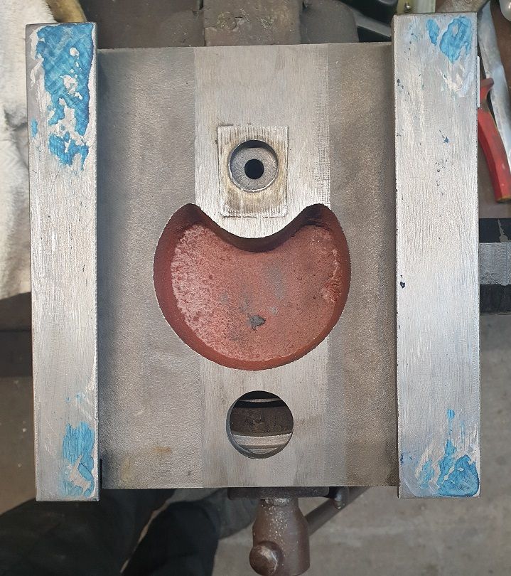
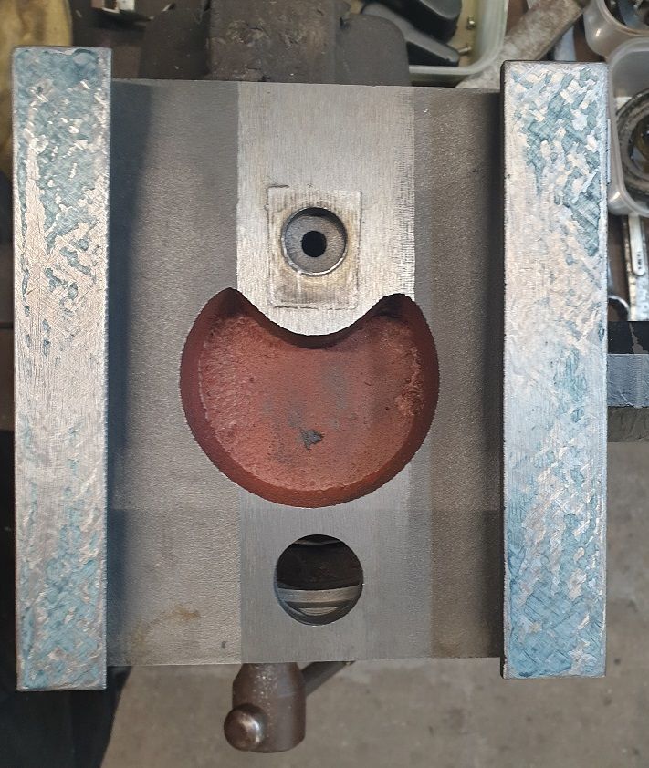
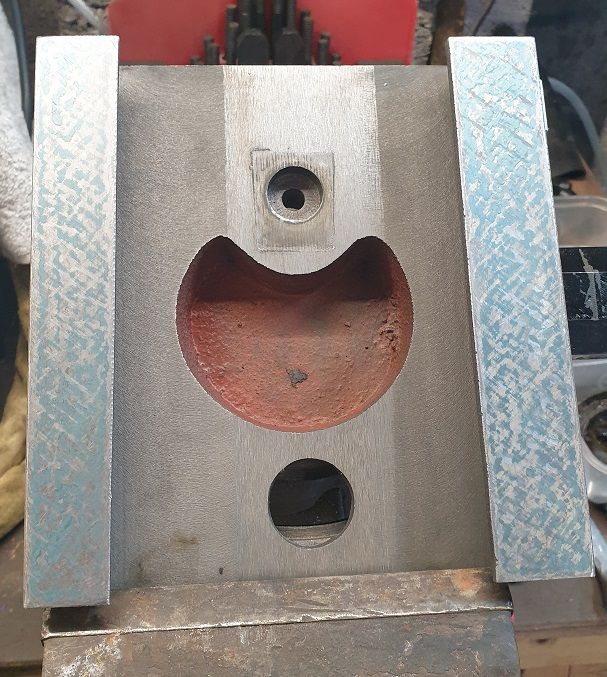
                  So this scraping lark.. please be gentle, it's the first time I've ever had a go at it.

                  Wasn't expecting much but thought I could at least have a go at making the vertical saddle ways flat so I can then fix it to the lathe face plate once that is trued and re turn the head mounting face..

                  Had to do a few passes before there was anything to photograph, there was only a wee spot of blue on 3 corner tips!

                  saddle_ways_1.jpg

                  saddle_ways_4.jpg

                  saddle_ways_11.jpg

                  Might still have a fettle but considering how it was I'm pretty chuffed with that.. but, would welcome any constructive criticism..thumbs upbeer

                  #620812
                  Taf_Pembs
                  Participant
                    @taf_pembs

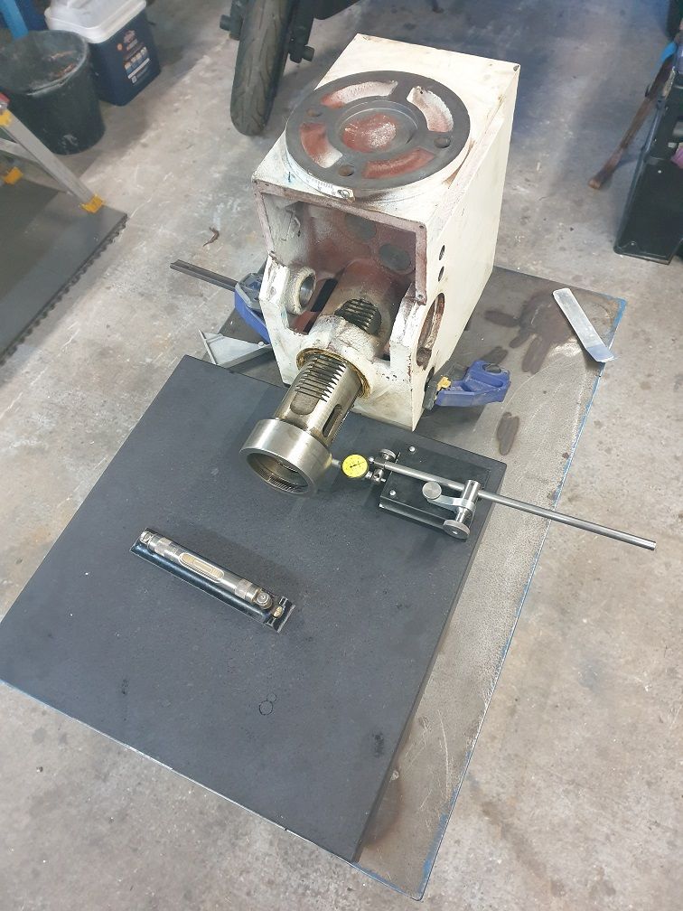
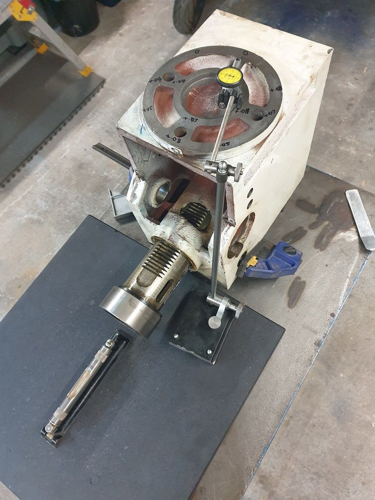
                    So that took up half of today too so then started on a full on Heath Robinson gaff up to see if I could actually measure and more importantly do anything about the head face..

                    Surface plate on table, head next to it and after much arsing about and lots of shimming I got them 'co planer' close enough with a machinist's level. then set about indicating off the partly extended quill and with another bucket load of shimming and faffing the surface plate was co planer with the quill (the pic should explain better!).

                    Then set about measuring the face. no real way of machining that so back to some scraping, lots of use of a new small single cut file, and wet n dry wrapped round a new (and remarkably flat!) Norton stone.. along with stoning too.

                    All that in between constantly re checking the alignment to make sure I hadn't moved anything and it is now within 0.02 all over. I appreciate the level of inaccuracy having such extended arms etc but it's the best i can do with what I've got. All the measurements are repeatable so cant be that far off!

                    head_face_measuring_1.jpg

                    head_face_measuring_2.jpg

                    Hopefully tomorrow will have it dressed and a decent surface on it ready to mount everything back together so I can check the column and work out a plan for that..frown

                    Right, Pub O'clock..laughbeer

                    Edited By Taf_Pembs on 12/11/2022 20:42:30

                    #620936
                    Taf_Pembs
                    Participant
                      @taf_pembs

                      Evenin' all..

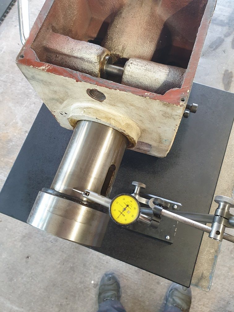
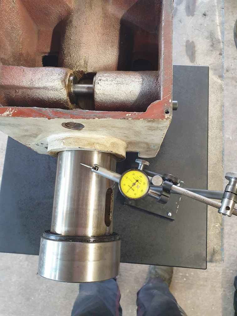
                      Bit more success today, having got the face true to the quill in the vertical as close as I could get with the oddly functional measuring set up it was time to get it on the face plate and get it flat enough to have a decent contact area.

                      To my utter surprise it actually worked! No, I didn't mess with the indicator between measurements..!

                      headface_check_1.jpg

                      headface_check_2.jpg

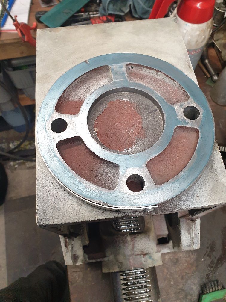
                      So on to dressing it proper flat for a decent contact face..

                      After lots of faffing about, I recon this will do. I'm going to leave a very slight relief around the bolt holes to allow for a bit of squish. The light is hiding some of the blue, it was a very thin print so hard to get the colour.

                      headface_done.jpg

                      Next bit of free time will be to dress my lathe face plate bob on then mount the vertical saddle to that and re cut the head face seat. Need to order some more brazing rods to build up the boss so I can turn that to suit the head recess so it has an accurate mount.

                      Hopefully once I've got all this as accurate as I can, when reassembled I can get a true measurement of what error there is in the column.

                      I think I'll then do as Pete suggested as first preference of taking the base to a firm to get the column seat face milled true, it not then John's suggestion of the resin sounds pretty good to me.

                      She'll get there! Food and Pint now..smileybeer

                      #620947
                      Michael Gilligan
                      Participant
                        @michaelgilligan61133

                        It looks like you are a ‘natural’ at this game, Taf yes

                        MichaelG.

                        #620965
                        Taf_Pembs
                        Participant
                          @taf_pembs

                          Thanks for the encouragement Michael, appreciate it yes

                          However, I believe 'natural' is something of a stretch!

                          If I can get it pretty close then it will give me the confidence to have a go at a proper one.

                          Have to say though, I've now experienced a tiny bit of scraping (badly but its flat!) and there is something oddly therapeutic about it. Love to be able to learn to do it properly..

                          I've been reading through Steve355's surface grinder thread, some good stuff there.

                          beer

                          #620991
                          Pete.
                          Participant
                            @pete-2

                            Nice work getting the two flats to have contact all along.

                            I'd definitely get the base skimmed with a fly cutter, it would be such a simple set up I doubt it would cost much, my worry if you used some kind of resin would be if you ever had to dismantle it, it might not go back properly with the base being so uneven.

                            Get in touch with small local machine shops and see if they can help, it's always good having a contact for the odd bigger job you can't do at home .

                            #621132
                            Taf_Pembs
                            Participant
                              @taf_pembs

                              Cheers Pete, hours of scratch and stone!

                              think I've just come up with a new band name..frown

                              Eye, from my quick measurements of the base, its too far out to manually bring back in.

                              #621166
                              david homer
                              Participant
                                @davidhomer12226

                                have you seen the videos on you tube by Stefan Gotteswinter about tramming his mill and using epoxy under the vertical column

                                David

                                #621187
                                Taf_Pembs
                                Participant
                                  @taf_pembs

                                  Hi David, not seen Stefan's video's on that yet, still trolling through his stuff.. will have a look though cheers!

                                  I have seen a fella on Youtube who machined up a 'wedge' ring that mounted between the column saddle and the head so he could rotate it and adjust the angle.. was a lot of work but the principle seemed very good.

                                  John Feeney had suggested using the SKC Resin to sort the base, if I don't get any joy with the couple of local (ish, I'm miles from anywhere!) machine shops about milling the base true then that will be next option..yes

                                  I would rather get it machined right as now I'm getting a little more confident in my ability to measure and adjust I am leaning more towards selling this one once it is bob on and getting something a little more substantial.

                                  Not that I need it, just enjoy messing with them! Saying that, I only bought the lathe as something to fiddle with and refurbish but have ended up doing a fair bit of work with it.

                                  beer

                                  #621268
                                  Taf_Pembs
                                  Participant
                                    @taf_pembs

                                    Well, after a bit of research and thanks to John & David's suggestions, I think I'll go down the epoxy resin route although as Pete has suggested, probably better to get the thing in the ball park by getting it milled first. Cheers folks!

                                    Looking at the specs for the SKC resin the recommended gap is about 2 – 3 mm so with a bit of tidying up by me that should work spot on.

                                    I'll leave it until the vary last job so any improvements I end up making to the saddle / base / bed can be taken into account (they were pretty dam good going by initial measuring in X & Y) to get the finished dimensions as close to perfect as possible.. 

                                    I chucked the spindle up in the lathe to check for run out and other than being able to measure a few scratch marks there doesn't seem to be ay throw which was surprising although still to check the taper properly.. Phew! Would love to replace it with an R8 spindle but they seem to be rarer than hens teeth..

                                    Done a bit of shopping, new Timken P5 spec spindle bearings en route from France (couldn't find them anywhere online in the UK), they were just standard taper's fitted sad and the rest of the bearings and seals from the usual suspects here.. all SKF bearings as I have fitted hundreds of them over the years and always found them top quality.

                                    Got a week off next week so cant think what I'll be up to while the boss is in work!

                                    beer

                                    Edited By Taf_Pembs on 15/11/2022 22:41:44

                                    #621830
                                    Taf_Pembs
                                    Participant
                                      @taf_pembs

                                      Evenin' all!

                                      So I believe the 3 golden rules of tig welding are – get comfortable, get comfortable and make sure your comfortable…

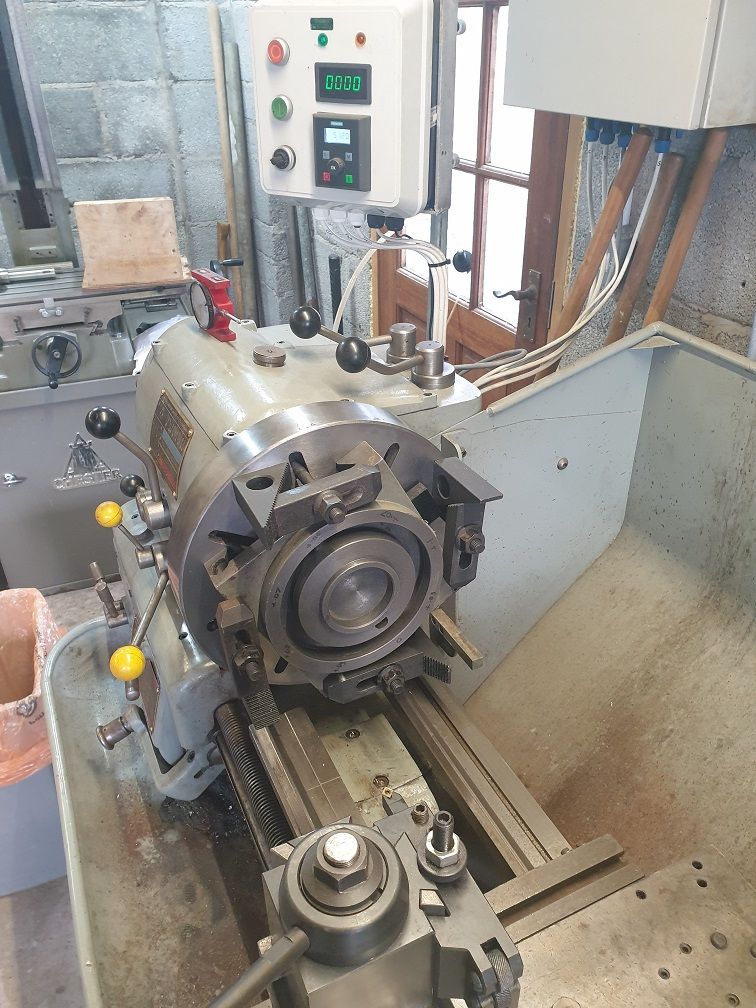
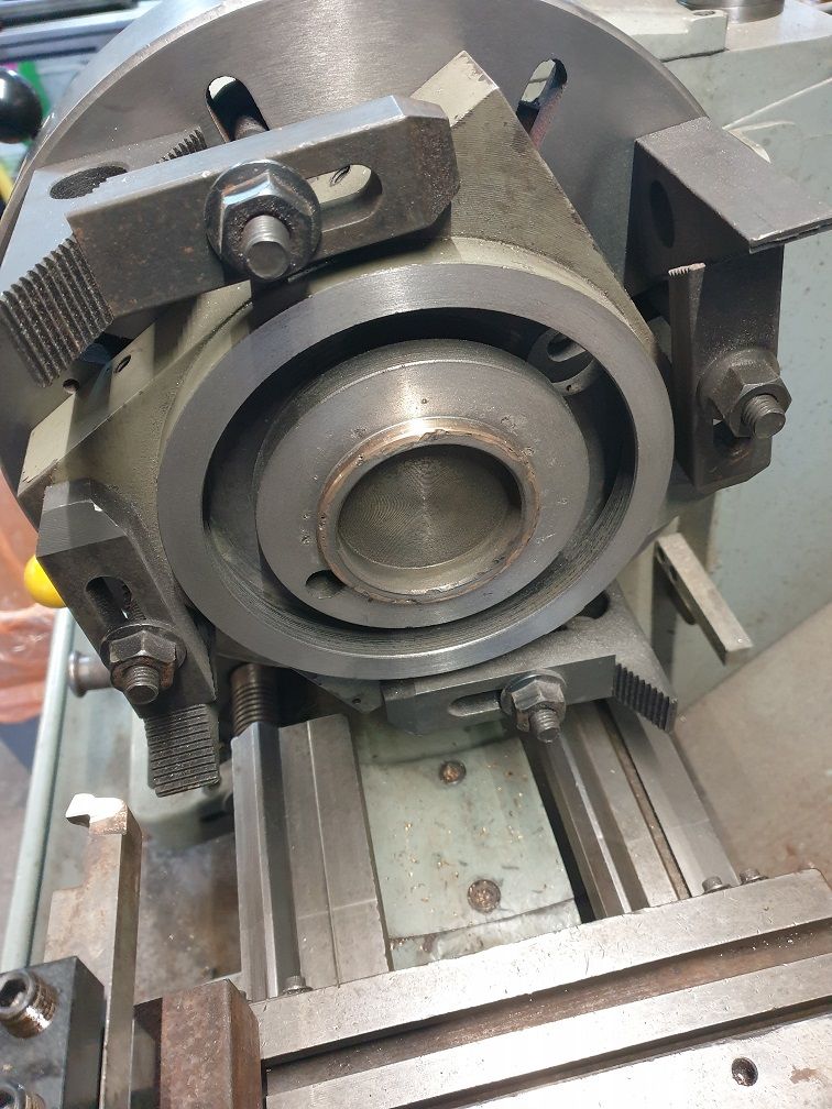
                                      Oh dear.. so leaning over the lathe having chucked up the vertical saddle on the face plate after giving it a wee skim to true it up so I could try to braze (I emphasize try as never tried tig brazing before!) the locating boss in the centre and what ever was digging in my ribs suddenly let go as I tried to adjust my view point.

                                      It was the toolpost locking lever.. not the most inconspicuous of things I know but there we are.. so with foot still on peddle (now at full beans as I was sliding over the top of the lathe) I managed to do a lovely job of dragging a 90amp arc right around the inner ring on the face.angry good job I had only set the thing to 90A, god knows what 200A would have done!

                                      Even dafter, while putting the last of the braze around the thing I coughed and added another couple of spots!

                                      And we all know what happens to cast iron when that happens. To quote a certain enjoyable youtuber loads of small spots that were harder than 'woodpecker lips'! I think the sticker he has on the front of his CNC machine is meant for me.crying

                                      After much careful spotting with a die grinder to try and recess all the tiny stupidly hard spots the face turned quite nicely, even if there are now a load of small shy spots.

                                      I also dressed the inner seats for the T bolts as the standard bolts have chewed the seats so very difficult to finely adjust the head rotation.

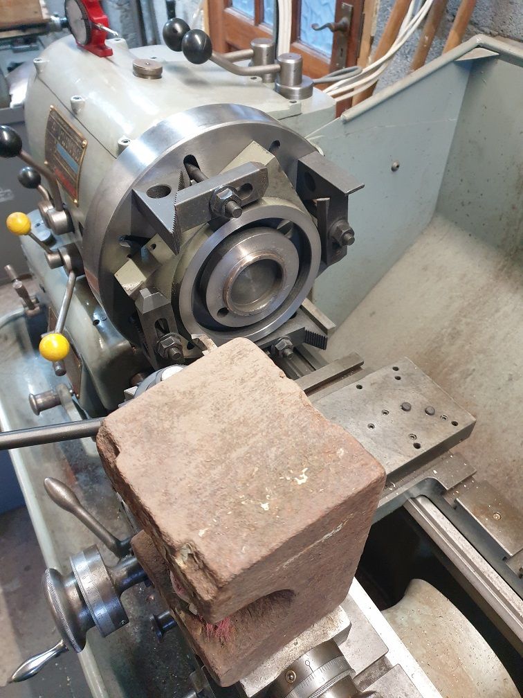
                                      The insert holder I had that would take my smallest inserts in order to take very fine cuts is only a 12mm stock so being stuck out far enough to clear all the mounting hardware and the compound being fairly well advanced to get in there quickly showed as one hell of a chatter squeal. Raided next doors garden and found a 25lb cast iron weight which when sat on the compound on 2 small slivers of wood worked a dream! smooth as anything so if your wondering what the hell that thing is in the photo ..

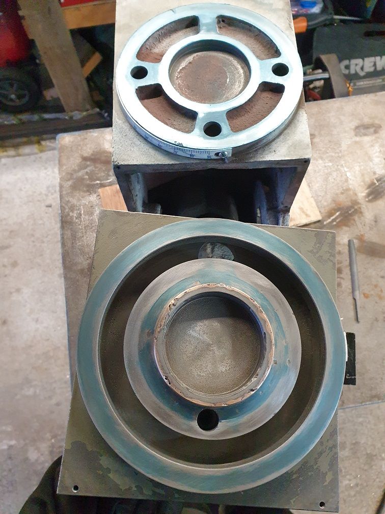
                                      All came good in the end, last pic is the almost finished face print. forgot to take a photo of the final one with a very light blueing but it was more than good enough..

                                      beer

                                      v_saddle_chuck_1.jpg

                                      v_saddle_post_braze.jpg

                                      v_saddle_turning.jpg

                                      v_saddle_check.jpg

                                      #622139
                                      Taf_Pembs
                                      Participant
                                        @taf_pembs

                                        Evenin' !

                                        Week off this week .. ish so between hospital, car service and other nonsense I might be able to get a bit done.

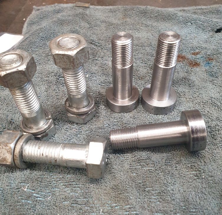
                                        Didn't get a great deal done today, stripped, de burred, cleaned and re assembled the gearbox shafts ready for re assembly.. it was pretty manky to say the least but all good now and made some new T-Bolts for mounting the head.

                                        Turned out OK, nice snug fit through the head face (17mm) reduced to M16 x 1.5 thread so don't need to be horsing up on them – single pointed and just ran a die down to tidy up, was a fairly hard piece of bar stock I found on the shelf, not sure what but she'll do!

                                        A much better contact area for the saddle too, just need to add the flats.

                                        Every bit done is a bit closer I suppose!

                                        The old ones were pretty crap..

                                        t_bolts_1.jpg

                                        #622385
                                        Taf_Pembs
                                        Participant
                                          @taf_pembs

                                          Evenin'!

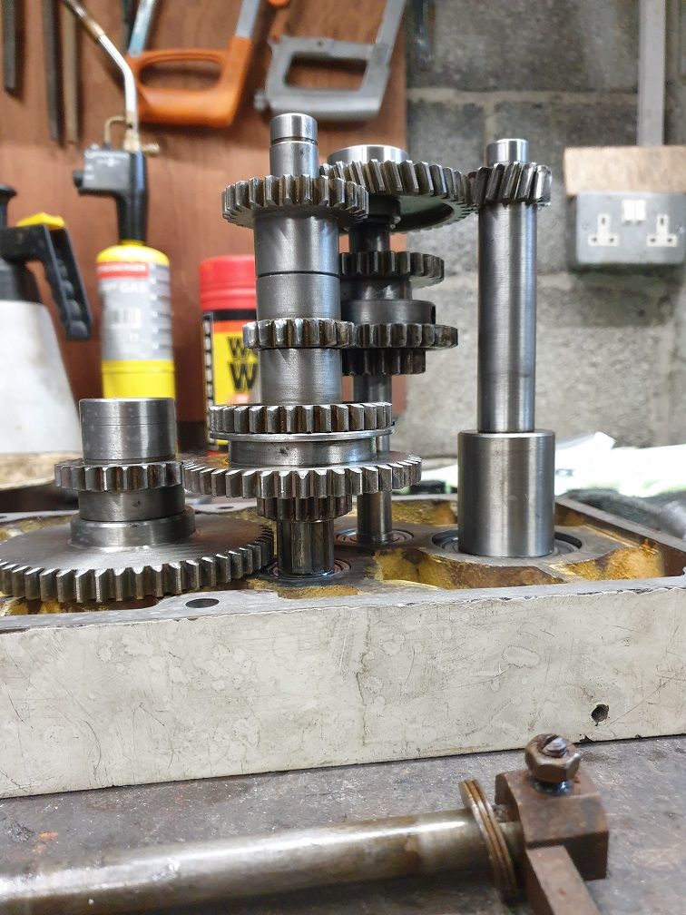
                                          When I dismantled the head, I was surprised at how poorly the gears meshed, by that I mean vertical alignment, and the fact that there was no 'neutral' position so it would be possible to freely rotate the spindle.

                                          Anyway, after an awful lot of shim making, changing the thickness of bearing spacer rings, messing with the shafts etc etc and what seemed like builds and disassembling of the shafts into the head cover using the old bearings I have all shafts turning with fully meshed gears in all positions. thought I'd never get there..!

                                          And even better, the 3 position selector has a fairly large space when between 2 positions so that shaft now has a small detent so it will hold in a neutral position well clear of the other gears (I cant remember if it is between Low and High or High and Med, it's all been upside down!).

                                          All boxed up and spinning lovely & smooth.. the old chinesium bearings were proper rough and sloppy.. ah well, they all add to the scrap weight!

                                          Spindle build next.. then bolt the head to the saddle and lay it on the surface plate to re check the alignment with the quill properly assembled.

                                          Fingers crossed!

                                          beer

                                          head_gearshafts.jpg

                                          #622651
                                          Lathejack
                                          Participant
                                            @lathejack

                                            It has been quite interesting watching the dismantling and fixing of your geared head mill, with some good work correcting all the nastiness you found.

                                            Some of the gear teeth look a little worse for wear, but now you have the internals all cleaned, realigned and with fresh bearings it should still have a long trouble free life. There is even one pair of helical gears in there, is that long shaft with the helical gears meshing on the end actually the input shaft driven by the motor mounted on the top cover above it? It looks like the top cover sat upside down on the bench.

                                            Will be interested to see the work on the quill and spindle assembly.

                                            Edited By Lathejack on 25/11/2022 17:14:51

                                            #622667
                                            Taf_Pembs
                                            Participant
                                              @taf_pembs

                                              Cheers for that beer

                                              I only really started the write up as I couldn't find a great deal of info on doing this to begin with and thought it might help someone like me with naff all experience of these things. Now I know these are a pretty generic RF45 type machine and with the greatly appreciated help and suggestions of some folks on here I'm finding more on the interweb.

                                              Yes, the smaller diameter gears are a little on the grim side but I have now given them a dressing to remove any burrs and nasties so they should be OK. The pic is, as you say, the top cover of the gearhead with the shafts sitting in the old bearings and the input shaft on the right thumbs up

                                              I've made some aluminium blanks for the drift slots in the quill to keep the crap out of the spindle bearings but lost my JB weld to bond them in so that is maybe a job for tomorrow..

                                              Started on the XY saddle today , pics to follow.

                                              beerbeer

                                              #622670
                                              Taf_Pembs
                                              Participant
                                                @taf_pembs

                                                So managed a few more hours today.. now the gearhead is mostly reassembled – leaving spindle build etc till I've cleaned up a bit cos even Steptoe would be ashamed of the place at the mo!

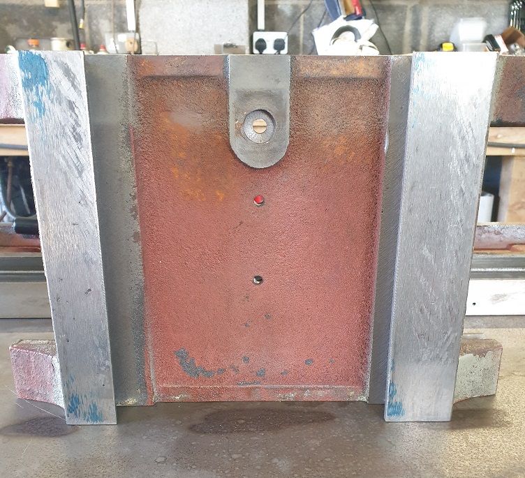
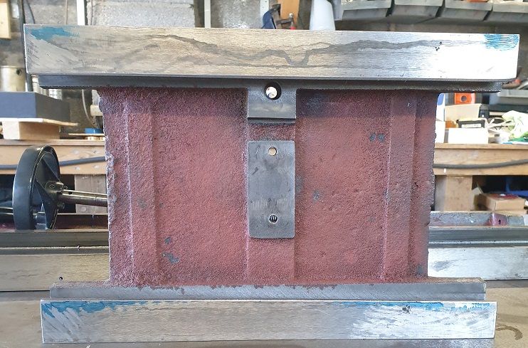
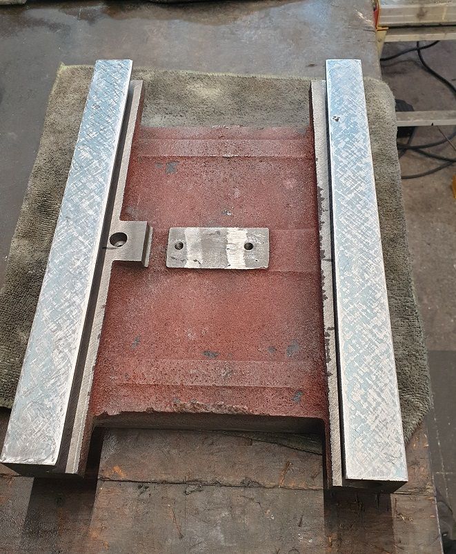
                                                Stripped the X Y Saddle and after a bit of cleaning started to get an idea of how it was.. be ways on the Base appear to have very little ware on them but then I don't have a straight edge / camel back to check (And can not afford one!) but the raised surface between them seems to be a ground (coarsely) surface so I presume that is the reference surface for hen they build the thing and will use that to depth mic the ways as best I can to check.

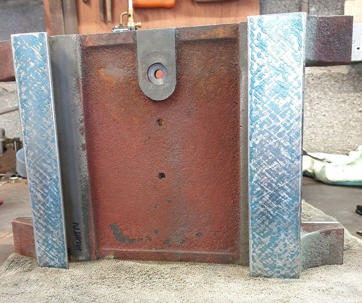
                                                Did an initial print of the saddle as below.. not the best!

                                                xy_saddle_y_print_1.jpgThe Y ways..

                                                xy_saddle_x_print_1.jpg The X Ways..

                                                So I set to the Y ways. I tried to take as finer scrapes as possible as didn't want to remove any more metal than absolutely necessary thinking that the oil pockets are best on the lower ways so not too fussed about the pattern, just want it flat.

                                                Am I right in this thinking? Or should I be taking some deeper scrapes and making more effort on the pattern and spots per inch?

                                                Anyway, this is nearly done –

                                                xy_saddle_y_print_2.jpg

                                                Lighting makes it look far more patchy than it is and its a bit heavy.. leaving it like that till I sort the below stuff.

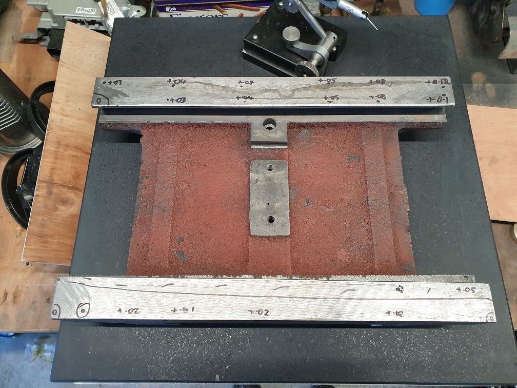
                                                I then set about taking some measurements to the X ways and the high area coincides with the initial Y ways print that was heavyest so need to do some more thinking and measuring to see if i need to try to step scrape the X Ways into co planer with the Y or take some more off the Y Ways to bring the high side of the X down a bit..

                                                xy_saddle_x_measurement_1.jpg

                                                Any thoughts?

                                                I suppose any error I get here could be taken out with the column adjustment though – not that that is the right way to do it I suppose!

                                                Which ever way I go, I presume the X ways will need an attempt to scrape properly with decent oil pockets being upward facing ?

                                                1 bonus though, I found an old Eclipse hand scraper so my modified file is fairly redundant!

                                                Foot and a pint now though..laugh

                                                beer

                                                #622870
                                                Taf_Pembs
                                                Participant
                                                  @taf_pembs

                                                  Evenin' all!

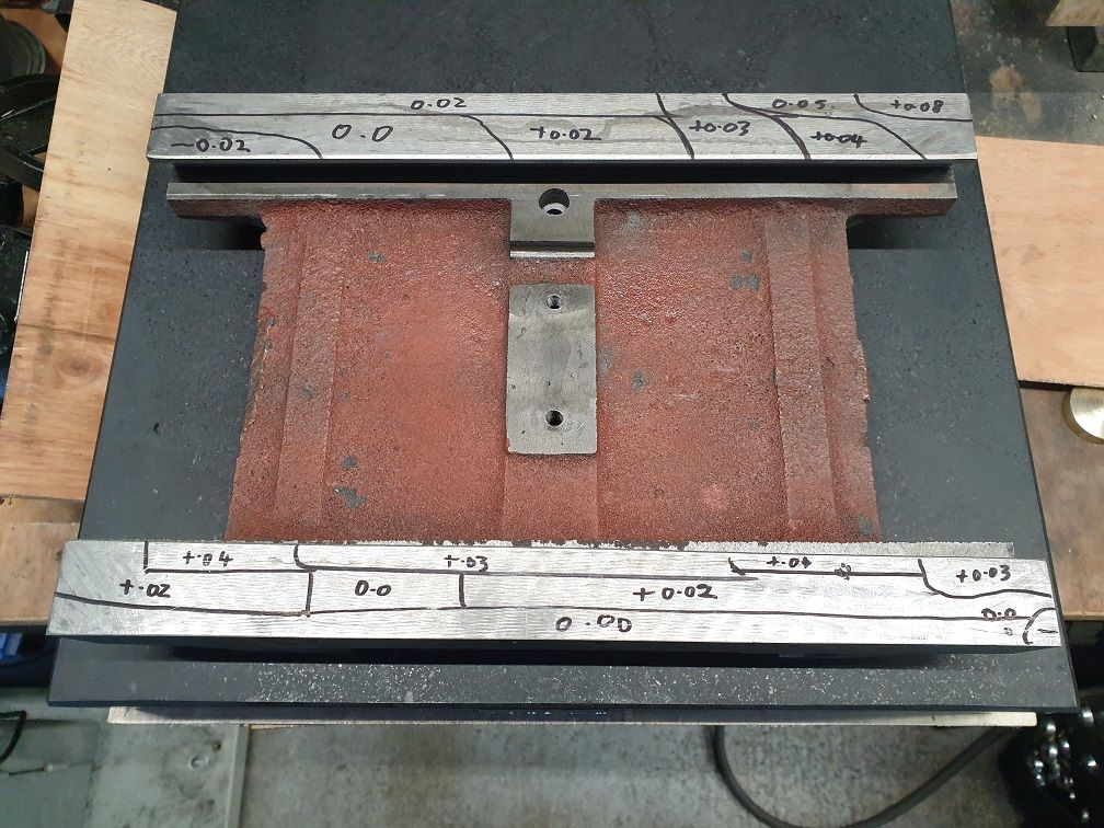
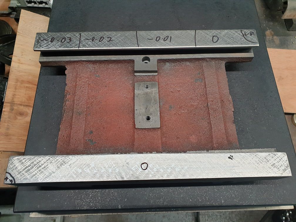
                                                  Got through a bit more, got the X Y Saddle finished.. after checking as best I could from the machined faces on the saddle, I decided to drop 1 of the y faces a round or 2 of scrapes and then have anther check which gave the results below.. much better so set too on the X faces..

                                                  xy_saddle_x_measurement_2.jpg

                                                  After a fair few rounds got it to this..

                                                  xy_saddle_x_measurement_3.jpg

                                                  And after a few more rounds of tweeking got the whole thing to 0 with a couple of spots that were -0.01 ..

                                                  All this of course is subject to the accuracy of the new surface plate. A Dasqua 450mm x 450mm x 80mm and according to them its a grade 00 .. Chronos were selling them recently for only £150 something. A grade 00 plate for that.. me thinks not but so far I can not complain, I can not measure any variation anywhere on it!

                                                  I ran a half thou indicator all over it on a 3" extension from the surface gauge base and the indicator barely twitched let alone move!

                                                  There are 2 tiny (match head sized) chips right in 1 of the corners so maybe thats the reason for the price but they affect nothing.

                                                  The print..

                                                  xy_saddle_x_print_2.jpg

                                                  Again, lighting is hiding almost all of it.. David Bailey I'm not.. but it's pretty much there.

                                                  Once I was happy I set to it as heavy as I could to scrape some oil pockets into the surface's and called it done.

                                                  Forgot the final photo but naff all difference really.

                                                  #622875
                                                  Taf_Pembs
                                                  Participant
                                                    @taf_pembs

                                                    So next I set about trying to check the Table itself.

                                                    After much cleaning and stoning I placed it top down on the surface plate. Yes, it's far too long with a fair bit of over hang so crap for taking any measurements. I ended up placing weights in the centre in an attempt to counter the over hang and with only about 14lbs of weight the indicator readings on the ways became perfectly repeatable even when moving the table slightly left & right so with that being the best I was able to achieve it would have to do.

                                                    Both sides were out over their width, very slight slope of about 0.05mm although from centre out towards the ends was spot on along the rear way and the front way was good 1 way but tapered down to 0.05 low about 10 inches out the other.

                                                    After many .. many finger aching hours of scratching and stoning both sides are within 0.02 which considering the probable inaccuracy in measuring is way better than I could hope for.. leave it alone now!

                                                    Again, forgot the pic.. was so excited that repeated set ups gave consistent readings!

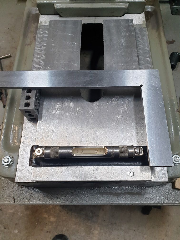
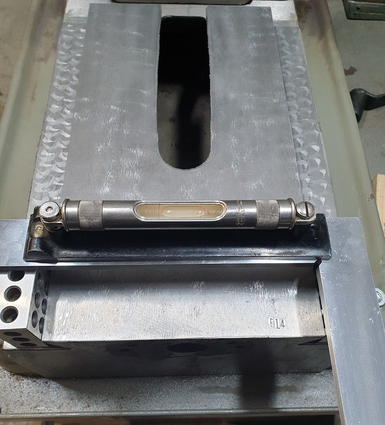
                                                    The Base ways.. cue a proper Heath Robinson set up but best I could come up with with what I had.

                                                    I used what appeared to be the ground face between the ways as I presume that is the reference surface for when they build the thing.

                                                    Put a machinist's level (as far as I can check it's a thou / foot, a J Rabone & Son's but no rating on it) on the freshly stoned surface and centred it with bubble just touching line on left.

                                                    base_ways_check_1.jpg

                                                    Then a pair of 123 blocks on each way and a so called precision square between (it was fairly cheap, not bad at all though) and the level on top. Moved along to 5 different positions down the ways with level and square positioned in same way on blocks each move.

                                                    base_ways_check_2.jpg

                                                    Worst position was the 1 above, 1 division out . Here we go with the scratching and stoning again..

                                                    Managed to get it so the rear half is bob on and just less than half a division on the level out at the front.

                                                    All things considered I think that will be good enough but I may have another attempt at because I know it's not quite there..blush

                                                    Think I deserve a pint now although I'll probably drop the bugger the fingers are aching so much!

                                                    beer

                                                    #622885
                                                    Taf_Pembs
                                                    Participant
                                                      @taf_pembs

                                                      Thinking about it, I suppose the best thing to do with the table would be to blue up the saddle and use that as a reference .. at least I could probably get the main middle portion bob on.. will have a look see in the week..

                                                      Could do the same with the base ways.

                                                    Viewing 25 posts - 26 through 50 (of 174 total)
                                                    • Please log in to reply to this topic. Registering is free and easy using the links on the menu at the top of this page.

                                                    Advert

                                                    Latest Replies

                                                    Home Forums Manual machine tools Topics

                                                    Viewing 25 topics - 1 through 25 (of 25 total)
                                                    Viewing 25 topics - 1 through 25 (of 25 total)

                                                    View full reply list.

                                                    Advert

                                                    Newsletter Sign-up