Centre Finding Round Bar with Edge Finder – Big Deal?

Advert

Centre Finding Round Bar with Edge Finder – Big Deal?

Home Forums Workshop Techniques Centre Finding Round Bar with Edge Finder – Big Deal?

Viewing 25 posts - 1 through 25 (of 34 total)
  • Author
    Posts
  • #16222
    Dr_GMJN
    Participant
      @dr_gmjn
      Advert
      #510663
      Dr_GMJN
      Participant
        @dr_gmjn

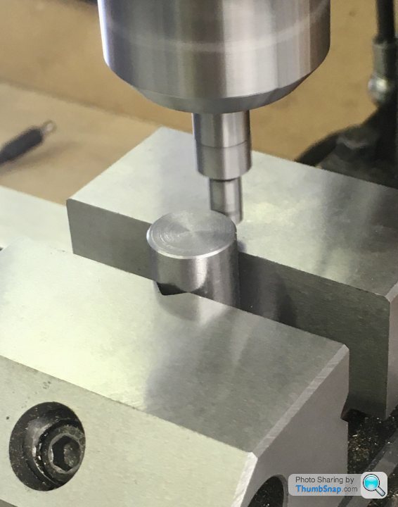
        All, a few weeks ago, I posted an update on my 10V build on another model forum (Pistonheads, not specifically M.E. based). It was regarding spotting the eccentric centre and offset, for subsequent placing in the 4 jaw lathe chuck. I’m no expert, and used my edge finder in a way that I’d been doing fairly routinely during the build, with no apparent issues. This is the relevant part of the post:

        “Then transferred to the mill and got the centre with the edge finder:

        Someone responded with this comment:

        “Why on earth are you using a round edge finder to try to find a datum on a round part?

        You have a perfectly straight vice jaw to use the edge finder on instead of hoping the edge finder is on centre with the round part.

        Or just buy one of these…

        **LINK**

        My response was that I’m not “hoping” the edge finder is on centre, because it’s irrelevant – initially it’s equally offset from the centre on both sides. Once that’s established, the opposite axis centre can be found. Also that even if it’s slightly inaccurate, the drawings aren’t tolerances, so it doesn’t really matter, and why would I spend money on a device that I don’t need? The response was:

        “In 30+ years of precision engineering I have never seen anyone try to set a datum on a round part like that because if they did they would get laughed out of the factory!

        A moving jaw is irrelevant for setting a datum, set the datum off the fixed jaw and work back from that if you want to do it the hard way or just buy the correct tool for the job which will be quicker, easier and more accurate.”

        I don’t know how I was supposed to get the axis in the direction parallel to the jaws – they never responded after that.

        Any thoughts?

        #510667
        JasonB
        Moderator
          @jasonb

          Oh Bu**er you mean I've been doing it wrong too.

          I have one of the co-axial finders but seldom use it, I tend to use an electronic finder rather then the type you show but makes little difference. may sometimes use the vice jaws for Y=axis but touch the sides of the round part for the X axis and if the part is not in the vice I just touch the work for both. Also do it for internal holes.

          As you say it does mot have to be on ctr as you are measuring each end of a cord.

          The quality of your finished model shows you have little to worry about.

          Edited By JasonB on 29/11/2020 17:45:13

          #510671
          Ramon Wilson
          Participant
            @ramonwilson3
            Posted by JasonB on 29/11/2020 17:44:15:

            The quality of your finished model shows you have little to worry about.

            Exactly – but your questioner does have a point – unless the centre line of the edge finder is directly on the centreline of the part then you do not have a reference. If you touch on opposite sides at the same X or Y setting then you are doing no different that using a dti to find the centre – to my mind (and training) much the better option.

            There's a fair few ways of dealing with eccentrics and I wouldn't say I would use that one but you got there – and that's the important bit.

            Good to see you posting again – when are you starting on the PR

            Regards – Ramon

            #510676
            Dr_GMJN
            Participant
              @dr_gmjn

              OK guys, interesting.

              Ramon, if the initial reading was, say, 2mm offset from the centre, I lift it and move to the opposite side (as I did), then it’s still 2mm offset, therefore isn’t the offset from the true centre exactly the same? Therefore half it, and it’s still bang in the centre?

              Bit of a lull at present – it’s cold out there!

              #510680
              JasonB
              Moderator
                @jasonb
                Posted by Dr_GMJN on 29/11/2020 18:19:58:

                OK guys, interesting.

                Ramon, if the initial reading was, say, 2mm offset from the centre, I lift it and move to the opposite side (as I did), then it’s still 2mm offset, therefore isn’t the offset from the true centre exactly the same? Therefore half it, and it’s still bang in the centre?

                That's my thinking you are measuring a cord half of which will put you on ctr line. If in doubt do say Y first, then set to the middle, do x and finally go back to check Y if you really want the accuracy. The few times I've done that I have been within a 10th thou so seldom bother.

                #510685
                Dr_GMJN
                Participant
                  @dr_gmjn

                  Jason, yes, that’s exactly what I do, and invariably it’s exactly the same reading.

                  So I wonder why is it not thought a good way of doing it? I can’t think of any reason why it’s less accurate than using vice jaws, in fact it surely eliminates any slight compression of the part from the jaws?

                  I did point out that this isn’t “industry”, and therefore using available tools seemed fine. As I said I got no further responses, just a criticism, and…gone.

                  #510687
                  Baz
                  Participant
                    @baz89810

                    Nothing wrong with your method of centre finding, I would have liked a bigger vee to locate the vertical axis, I would worry that you may get marking from the edges of the vee on the vice jaw. As said above all you are doing is halving a chord. If I recall correctly this method was described in the Guy Lautard Machinists books, can’t remember which one though!

                    #510689
                    JasonB
                    Moderator
                      @jasonb

                      Infact looking at your picture had you used the vice jaws you would have got a wrong reading as the Vee in your moving jaw will allow some of the round stock to sit within the face of the jaw.

                      Your quote does say "jaw" though so maybe they were suggesting just locating the fixed jaw and then calculating half dia and any backlash compensation which sounds less accurate to me. Or maybe they thought you were just touching off on one side of the bar and then moving by half dia in which case it would give a wrong reading.

                      Edited By JasonB on 29/11/2020 18:50:37

                      #510693
                      Anonymous
                        Posted by Baz on 29/11/2020 18:45:44:

                        If I recall correctly this method was described in the Guy Lautard Machinists books, can’t remember which one though!

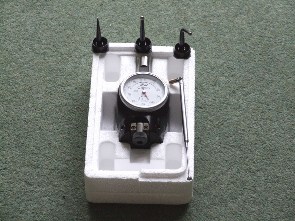
                        The second one – it's called Osborne's Maneuver. It's different from the method described above in that it is an iterative process and ends up with the X and Y axes aligned with the centre of the work. Of course it was developed before DROs were commonplace. I have used it in the past, but now I just use a co-axial indicator:

                        centro.jpg

                        Quicker than faffing about with edge finders. smile

                        Andrew

                        #510695
                        Ramon Wilson
                        Participant
                          @ramonwilson3

                          No theres nothing 'wrong' with the technique but just not one used (certainly in my working experience) to locate a centre.

                          If it 'works for you' however and it's not an unsafe practice then by all means do what you feel. It's the end result that counts.

                          Were I to do it Doc I would have established the centre clocking the diameter and moving x and y to the offset but that's how I was taught.

                          We all have certain ways of how we work and there are certain things that would be frowned upon but if it gets the job done satisfactorily who is 'right' to say somethings is 'wrong'!

                          Regards – Ramon

                          #510696
                          old mart
                          Participant
                            @oldmart

                            I would start with the edge of the vise jaw and move to the centre line, easier said than done unless you know the exact ammount of backlash in that axis. Then I would know that the probe was exactly tangential to the second axis. I use a Vertex electronic probe with a 10mm ball at the end. The second axis would be achieved by the same method, knowing the backlash in the other axis. Of course, the backlash will vary slightly as there will be uneven wear in the leadscrews. With a DRO, life would be so much simpler and accurate. I also have one of the co-axial centre finders, it would probably be more accurate and save time.

                            Edited By old mart on 29/11/2020 19:23:34

                            #510697
                            Martin Kyte
                            Participant
                              @martinkyte99762

                              or grip the part in the drill chuck and then clamp the vice.

                              regards Martin

                              #510698
                              SillyOldDuffer
                              Moderator
                                @sillyoldduffer
                                Posted by Dr_GMJN on 29/11/2020 18:41:17:

                                As I said I got no further responses, just a criticism, and…gone.

                                Someone got it wrong. Not you!

                                smiley

                                #510701
                                Baz
                                Participant
                                  @baz89810
                                  Posted by Andrew Johnston on 29/11/2020 19:02:28:

                                  Posted by Baz on 29/11/2020 18:45:44:

                                  If I recall correctly this method was described in the Guy Lautard Machinists books, can’t remember which one though!

                                  The second one – it's called Osborne's Maneuver. It's different from the method described above in that it is an iterative process and ends up with the X and Y axes aligned with the centre of the work. Of course it was developed before DROs were commonplace. I have used it in the past, but now I just use a co-axial indicator:

                                  centro.jpg

                                  Quicker than faffing about with edge finders. smile

                                  Andrew

                                  Trust me to get it wrong.

                                  #510703
                                  JasonB
                                  Moderator
                                    @jasonb

                                    I think the main reason that I don't use the co-axial indicator as much is that it needs the head winding up a long way, not such an issue on a knee mill but a lot of cranking on a small benchtop machine and that is provided you have the headroom once something to hold it with and the height of the work are taken into account.

                                    I do tend to use a dti more on the CNC as it's not as easy to damage by over jogging as the electronic one is.

                                    #510705
                                    duncan webster 1
                                    Participant
                                      @duncanwebster1

                                      I'm not convinced that the type of edge finder shown in the first post works all that well on round (convex) objects. On a flat surface as you approach the datum the moving bit gets pushed nearer and nearer to the rotating centre, just touching once per rev until it is on centre, any closer and it flicks off. With a convex surface as soon as it is moved off to one side it loses contact as the touching surface is curved. Obviously it works to some extent, but how well?

                                      However, for setting an eccentric throw which isn't all that critical I'd just grip a centre drill in the chuck and move it closer with a bright light shining down the gap till it touches. Do this in both X and Y both sides so you are offsetting along one of the axes. This only works if you have a dro, backlash messes it up otherwise

                                      #510708
                                      Dr_GMJN
                                      Participant
                                        @dr_gmjn

                                        Thanks all. I’m just trying to understand the comment. It’s all fine – the eccentric throw was ok and the engine worked.

                                        I do have a DRO (just scales and x,y,z read outs that I can zero). I just touch on the part, zero, touch the other side and half the figure, then move the axis to that figure and zero. Repeat for the other axis and 0,0 is what I take as the centre. I triple-check the touch readings at the time to make sure they repeat, and also check that the quadrants are equal figures from the 0,0.

                                        #510721
                                        Ramon Wilson
                                        Participant
                                          @ramonwilson3

                                          A factor to possibly consider when touching on a circular surface with an edge finder is that it the spindle is running the same way the moving button will run 'up' a slope on one side and 'down' on the the other – whether that has any direct influence I'm not certain but on a flat surface its constant.

                                          I do have edge finders but can't use them on the Linley so usually its a 6mm dowel and a cigarette paper – done fine for me so farwink

                                          Ramon

                                          #510726
                                          Dr_GMJN
                                          Participant
                                            @dr_gmjn

                                            Thanks Ramon, I did consider the tangent contact. In theory, once I’ve found the chord (offset) centre, the next two touches should be on the apex (quadrant point) of the circle, so the finder is not running up or down a surface. Same on the subsequent check of the initial centreline.

                                            Id have thought that contact is contact, and that subsequent climbing or descending of the finder on the surface wouldn’t matter.

                                            It sounds to me like there’s no real issue with the method I used – at least not for this kind of work – and that whoever made the comment was perhaps more intent on being clever/negative/snide, than wanting to offer useful advice. Their comment about the initial touches not giving the centreline because they’re not at the apex also suggested to me that they didn’t really understand the method I was using.

                                            Thanks all.

                                            #510786
                                            Martin Connelly
                                            Participant
                                              @martinconnelly55370

                                              If i use an edge finder on a curved surface I reverse the spindle rotation on one side so that the process is exactly mirrored to avoid slight differences due to geometry if you are not exactly on centre, I've never checked if it makes a difference but it keeps me happy.

                                              Here's how it's done with CNC, it may look like a recognisable process that doesn't use a DTI.

                                               
                                              Martin C

                                              Edited By Martin Connelly on 30/11/2020 09:00:41

                                              #510800
                                              Dr_GMJN
                                              Participant
                                                @dr_gmjn

                                                Thanks Martin. I can't reverse the spindle on mine.

                                                #510822
                                                Gary Wooding
                                                Participant
                                                  @garywooding25363

                                                  I always use an edgefinder to centrefind a cylinder but, mindful of the possible problem of spindle rotation having a lopsided effect on the moment the indicator 'fliicks', I always do it twice. I first determine the Y-axis centre by-eye and then get a first X-axis centre with the edgefinder. I then use this X-axis centre to get the initial Y-axis centre, and then use that position to get a possibly better X-axis centre, and then repeat to get the better Y-axis centre.

                                                  Even if it doesn't actually get a better result, it allows me to think it does.

                                                  #510829
                                                  Paul Lousick
                                                  Participant
                                                    @paullousick59116

                                                    For less accurate centreing I use an edge finder as shown in the first post.

                                                    I don't have a co-axial indicator for more accurate centre locating, instead use a dial indicator attached to an arm, mounted in the chuck. (either a plunger type or lever type) Turn the chuck by hand and adjust the mill table to get a constant reading on the DI.

                                                    Paul.

                                                    #510838
                                                    Ramon Wilson
                                                    Participant
                                                      @ramonwilson3

                                                      The luxury of a co-axial indicator would be nice but it would be too long for my Linley mill. I do use a small .001mm dti on an adjustable arm though exactly as Paul describes. I just turn to it automatically for finding the centre of anything round on the mill – to me it's very much the tool for the job but that doesn't mean to say it's the only tool wink

                                                      Ramon

                                                    Viewing 25 posts - 1 through 25 (of 34 total)
                                                    • Please log in to reply to this topic. Registering is free and easy using the links on the menu at the top of this page.

                                                    Advert

                                                    Latest Replies

                                                    Home Forums Workshop Techniques Topics

                                                    Viewing 25 topics - 1 through 25 (of 25 total)
                                                    Viewing 25 topics - 1 through 25 (of 25 total)

                                                    View full reply list.

                                                    Advert

                                                    Newsletter Sign-up