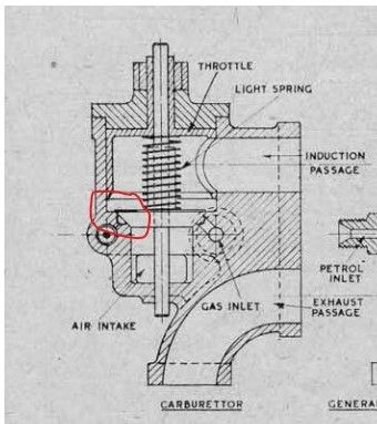
I'm a little way into building an ETW "Centaur", my first ICE project.
The design of the carburettor body shows a groove machined around the air-valve seating to divide the seat into 2 separate lands. Can anyone explain what this groove achieves? Drill-ways for the fuel open into it, but when the valve is closed then they are shut off and when the valve lifts off its seat then the groove seems pointless.
Machining this groove at the bottom of the bore will be quite tricky for accurate position so, if it is essential, would a groove in the air-valve itself, rather than the carb. body do the same job?
Clive, I constructed one of these 2/3 years ago (photos in my album) and I wondered about the groove. As you say a bit tricky down the bore of the carb! I did put the groove in the seat but unless someone could come up with a good reason it would be relatively easy to have a valve with and one without the groove, and try it? On the face of it it sounds a good idea.
The only downside would be if you decided it was needed in the seat, setting it up again to run true for machining could be a pain.
On my Centaur carburettor I just had the plain seating no groove as I couldn't see the reason for having a groove, the engine ran and started with no problems.
Clive, ETW describes a similar, grooved seat carburettor on page 124 of his book "Model Petrol Engines" (Tee publishing). He also describes how it's supposed to work. This carb. apparently introduces all its fuel via the groove whereas I gather the Centaur carb. must have a second way of introducing fuel since it runs without the groove. If you need further details, PM me and I'll attempt to scan the relevant pages for you.