Been developing this for quite a while and have it pretty much as I originally imagined.
System uses largely off the shelf items and some modification/additions as required.
Basic parts are the 4 wire 12V DC "black box" CDI units, GY6 Ignition coil and the KY_003 hall effect module. For the HT coil wire, I cut the 1/4" thick HT lead close to the coil, strip back and add whatever length of Belden high voltage cable. This is around 4 mm thick and scale to some degree. In a couple of units for my mate George Punter whom some of you may know, I added a 1A diode in the power supply (Just in case……💥
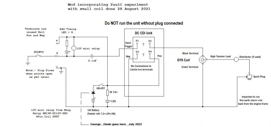
Additional parts are a 2.5mm spacing 0.1uF capacitor, LED and 1k0 resistor, HK-19F DC12V SHG 8 pin relay (only uses the coil in the circuit) some small bridging cable, a miniature switch on off, and the add on board. Naturally as in the beginning, some veroboard could be used.
Seen all over in places like Ebay etc. and when I started out the above bits were around AUD$15 in total, now perhaps double that but still worthwhile.
The original CDI black box ran a pickup coil which was large and cumbersome for model work hence the need to convert to hall effect pick up. I have just completed a changeover on my Atkinson engine and it uses points. Although the unit is originally designed for 12v DC, this latter application works well on a 2s LiPo @7.4v DC.
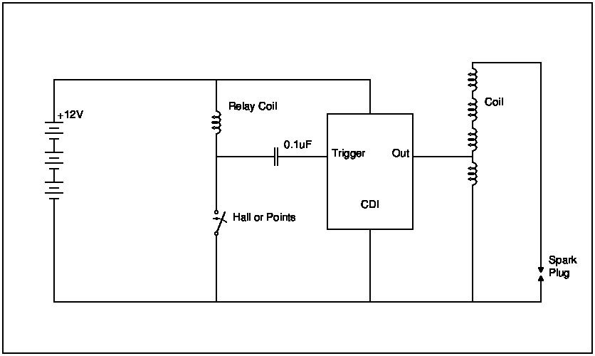
To get the unit to function properly, it needed addition of some type of "coil kick" in the sensor. I played with this for a quite a while and during some discussion a fellow model maker, PaulC from homemodelenginemachinist literally fell on the idea of an inductive "reed coil" in the hall circuit and hence the CDI trigger which made all the difference. He added a transistor stage to the hall output to drive the reed coil but I have since found this unnecessary.
I simply added a miniature oftheshelf complete mini relay and use just the coil in circuit leaving the rest of the unit intact. The hall effect module has an onboard LED to use for timing settings.
The add-on board I designed, carries the above relay, connections for a power LED and resistor, connections for the hall effect module and connections to the CDI black box unit.
In the latter I now tend to keep power to the CDI black box and on off switch separate as those pcb traces seem mighty small when one gets to actually see it in real life, different to on the screen design. (EasyEDA)
If using in this manner then just battery power pos and neg to the add on board for the power LED, wiring to the KY-003 hall module and the trigger input wire from the add on pcb to terminal P1 on the CDI black box.
Important to emphasise the need to run a good earth from the battery negative to the engine frame for the spark return for obvious reasons.
Anyhow, I'll drop the files for the add on board and the circuit diagrams for both hall effetc and good old points in below. Points btw need just the hall effect signal wire and terminate the unused pos and neg.
Cheers Jorgo
Tried to upload jpg images of the schematics and a zip file with Gerber files for the add on board……no luck
ok then try this….go to this link….. go to post #184
https://www.homemodelenginemachinist.com/threads/model-engine-cdi-easy-and-cheap.31128/page-10
Edited By Jeff Jorgensen on 10/08/2022 00:48:26
mike T.


