Carbon fibre pendulum rod

Advert

Carbon fibre pendulum rod

Home Forums Related Hobbies including Vehicle Restoration Carbon fibre pendulum rod

Viewing 25 posts - 26 through 50 (of 99 total)
  • Author
    Posts
  • #486447
    Alan Crawley
    Participant
      @alancrawley27839

      Regarding the distance the weights descend and the height of the case, i have managed to calculate that it does not need sixteen turns on the barrels but about fourteen for a month going, and that there is probably just enough room if the weights are wound up to their limit.

      I am completely out of my depth now with the information about pendulums that I don't understand regarding the comment I quoted about bob weight being unimportant. I read this in a couple of publications from respected clock makers, and during my process of crude lash-ups to see if my creation would run (an 'expert' told me it had no chance of running because I used involute tooth form) I used various objects on the pendulum rod ranging between around 2 kilo to the correct 4kilo as designed weight for no difference in timekeeping over periods of 36-48 hours. With the correct weight it has run several days spot on.

      Advert
      #486451
      duncan webster 1
      Participant
        @duncanwebster1

        For a definitive view on cycloid vs involute see **LINK**

        If you change the mass of a pendulum bob without changing the radius of gyration (RoG) it doesn't affect the rate, but as Andrew points out the bob isn't all of the story, the rod has mass which moves the effective centre up from the centre of the bob, and so making the bob heavier also increases the RoG. Setting Big Ben by adding pennies on top of the pendulum works by reducing the RoG

        Radius of gyration is the distance from the pivot to the centre of oscillation see

        **LINK**

        #486455
        SillyOldDuffer
        Moderator
          @sillyoldduffer
          Posted by Alan Crawley on 18/07/2020 14:39:08:

          I am completely out of my depth now with the information about pendulums that I don't understand regarding the comment I quoted about bob weight being unimportant. I read this in a couple of publications from respected clock makers, and during my process of crude lash-ups to see if my creation would run (an 'expert' told me it had no chance of running because I used involute tooth form) I used various objects on the pendulum rod ranging between around 2 kilo to the correct 4kilo as designed weight for no difference in timekeeping over periods of 36-48 hours. With the correct weight it has run several days spot on.

          Everybody is right.

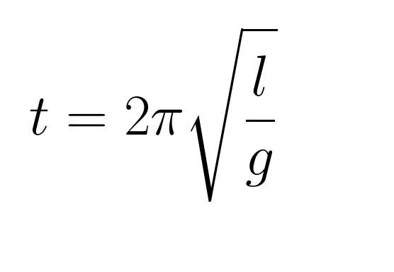
          The formula for period of a pendulum making small swings is:

          pendulum.jpg

          Where l is the length of the pendulum, and g is the acceleration due to gravity. No mention of mass in the equation, therefore confirmed the weight of the bob doesn't alter the period.

          But in a practical clock the bob has another vital purpose – it stores energy, keeping the pendulum going between ticks despite air resistance. It also helps keep the path straight rather than an ellipse, while its inertia reduces the effect of vibration.

          At the extreme, a pendulum clock fitted without a bob tends to stop because the impulse can't store enough energy in the rod alone.  Conversely, the impulse may not be strong enough to keep an excessively heavy bob going, or demand too much power of the clock for good timekeeping. So, although any bob between not too small and not too big will work, for any particular clock there'll be an optimum bob weight, and it's worth keeping close to it because it improves running.

          My only working clock so far was made of Meccano and it only had crude involute gears. All self-respecting clock experts should know that clocks can be made from a construction toy. But they're not wrong to be critical of them! Meccano clocks don't work well: difficult to adjust, poor timekeepers, and hard to keep going. A successful mechanical clock is a fight with friction, and a well-made gear train makes life much easier. Clock-makers believe cycloidal gears to be lower friction than involute. Not convinced myself; I think it would be hard to tell the difference between equally well-made clock wheels of either tooth form. I expect an expert will explain shortly why I'm wrong. Again!

          DaveI


          Edited By SillyOldDuffer on 18/07/2020 15:57:00

          #486457
          Anonymous

            I'm afraid SoD is incorrect. The formula he quotes is for a simple pendulum, the model of which explicitly assumes a weightless cord/rod and zero friction, neither of which is realistic.

            Once the pedulum rod has mass then, as Duncan says, the equations get more involved and include mass. That's why a compound pendulum is also known as a physical pendulum.

            Alan states that an expert said his clock wouldn't run due to involute gearing, which is plainly wrong. So why believe other experts when they say pendulum mass doesn't matter?

            Andrew

            #486458
            John Haine
            Participant
              @johnhaine32865

              Dave's formula is correct for a pendulum where all the mass can be assumed to be concentrated at the CoG of the bob. Real pendulums have distributed mass, some of which is in the rod above the bob; and the whole thing has a moment of inertia around its CoG (which is not the same as the CoG of the rod). The complete formula is:

              T = 2 pi sqrt{frac{I} {mgL}}

              where I is the MoI of the whole thing about the pivot, L is the distance from the pivot to the CoG of the whole, and m the total mass. If you add mass to the pendulum above the CoG of the bob, the CoG moves up and the pendulum will speed up slightly.

              If you make a pendulum to a design that used a steel rod but using CF instead, it is very much lighter than the steel, so will contribute much less to the MoI and because its mass above the bob is much less the clock will run slow for the same bob mass and rod length, so you may have to make the rod shorter.

              For accurate calculation you ideally have to include each component of the pendulum and compute the "radius of gyration" and mass. This is easily done with a spreadsheet though it's tedious to make sure you have all the components. Then Excel can use its solver to find the exact length to give the period you want. For most purposes the answer is the same as the simple formula, but for example the pendulum on the replica "RAS" clocks being built by a BHI team, which uses a gridiron pendulum with a relatively small bob, the spreadsheet is quite elaborate.

              #486465
              Russell Eberhardt
              Participant
                @russelleberhardt48058

                I used a pultruded carbon fibre tube for the pendulum of my regulator. I used 7 mm O.D. and 1 mm wall thickness. It has supported a 5 kg bob for the last five years without problems. I used slow cure Araldite to glue steel fittings to the ends. The fibre tube manufacturer quoted -0.1 to -0.3 ppm/°C and I have no reason to doubt that. You have to remember that the bob, suspension, and rod end fittings will all have a positive expansion coefficient but the threaded end of the rod for the regulating nut, combined with the bob itself can be made to approximately balance the expansion of the suspension.

                The only unexpected effect I noticed was that the clock gradually slowed down over the first six months or so as the rod crept under load but it then settled down. I guess that was a result of the stress being redistributed from the epoxy to the carbon.

                Hope that helps.

                Russell

                #486467
                Alan Crawley
                Participant
                  @alancrawley27839

                  This has produced some interesting replies and I particularly liked Duncan's link about gearing. That's life-we all enjoy the situation of "tell us what we want to hear" I wish I had read it earlier and I would not have worried so much about many hours of work being in vain.

                  Lockdown has at least given me the time to spend on this project and after over sixty years in engineering/toolmaking, and nearly fifty with my own small specialist business, I can still get immense enjoyment from something new and different.

                  You won't be able to imagine my excitement after a few little setbacks, how excited I was when this clock settled down and ran on its initial test.

                  I have one other small query about the CF rod, will it be ok where it is subjected to the friction of the crutch? This consists of two 3mm silver steel pins in a brass disc that can be rotated to adjust clearance to the pendulum rod. I would like to thank everyone who has taken the trouble to help me with my project.

                  #486468
                  Tim Stevens
                  Participant
                    @timstevens64731

                    You ask about flexibility of carbon fibre in this application. The forces on a clock pendulum tend to lengthen it (very slightly) each mid-tick, but not to bend or twist it, once the clock is going, so flexing is not an issue to worry about. Setting it up might cause twisting but only minor and it will spring back and overshoot a few degrees each side for a few seconds only. And a tube will resist twisting better than a rod of the same mass (but its air resistance will be greater).

                    The 'best' shape is a squashed oval in section, and Victorian wood pendulums are often this shape – but finding a metre of carbon fibre tube of this section might be impossible. The object of this shape is to reduce the air resistance to a minimum.

                    Hope this helps

                    Tim

                    #486469
                    Tim Stevens
                    Participant
                      @timstevens64731

                      Sorry – came up twice … !

                      You ask about flexibility of carbon fibre in this application. The forces on a clock pendulum tend to lengthen it (very slightly) each mid-tick, but not to bend or twist it, once the clock is going, so flexing is not an issue to worry about. Setting it up might cause twisting but only minor and it will spring back and overshoot a few degrees each side for a few seconds only. And a tube will resist twisting better than a rod of the same mass (but its air resistance will be greater).

                      The 'best' shape is a squashed oval in section, and Victorian wood pendulums are often this shape – but finding a metre of carbon fibre tube of this section might be impossible. The object of this shape is to reduce the air resistance to a minimum.

                      Hope this helps

                      Tim

                      Edited By Tim Stevens on 18/07/2020 17:52:59

                      #486494
                      John Haine
                      Participant
                        @johnhaine32865

                        I have seen elliptical cross section CF tube somewhere actually.

                        My pendulum rod is 10mm dia x 8mm bore CF tube. Being in an "Arduino" style clock it is impulsed every minute, and it is definitely observable that there is a small lateral vibration of the rod just after impulse. You can just see this by looking carefully, and it also shows up in the detailed electronic timing measurements though it doesn't seem to have any effect on the long term timekeeping. It isn't clear whether it is the rod flexing or caused by the impulse not being through the "centre of percussion", which for a very light rod is much closer to the bob.

                        #486501
                        Anonymous

                          Elliptical, oval and rectangular carbon fibre tube is available from some model boat and aircraft suppliers.

                          Andrew

                          #486503
                          Emgee
                          Participant
                            @emgee

                            I'm sure that if anyone on here needs any specific shape or size of carbon rod/tube it could be produced by some of the current membership, at reasonable cost of course.

                            Emgee

                            #486514
                            Sam Longley 1
                            Participant
                              @samlongley1

                              In model RC planes I use arrow shaft blanks. Stiff, cheap & 1 metre long

                              Edited By Sam Longley 1 on 19/07/2020 07:57:33

                              #486545
                              Russell Eberhardt
                              Participant
                                @russelleberhardt48058
                                Posted by Alan Crawley on 18/07/2020 17:41:45:

                                I have one other small query about the CF rod, will it be ok where it is subjected to the friction of the crutch? This consists of two 3mm silver steel pins in a brass disc that can be rotated to adjust clearance to the pendulum rod. I would like to thank everyone who has taken the trouble to help me with my project.

                                I had the same worry at first but my regulator has the same type of crutch and, after five years of running, I can't see any mark on the CF tube.

                                Russell

                                #486546
                                Russell Eberhardt
                                Participant
                                  @russelleberhardt48058
                                  Posted by Emgee on 18/07/2020 23:26:52:

                                  I'm sure that if anyone on here needs any specific shape or size of carbon rod/tube it could be produced by some of the current membership, at reasonable cost of course.

                                  Emgee

                                  That is if anyone has the equipment to do pulltruding. A normal lamination will not be stable enough.

                                  Russell

                                  #489924
                                  Alan Crawley
                                  Participant
                                    @alancrawley27839

                                    i have now made up a carbon fibre pendulum rod with glued and pinned threaded ends.

                                    The original design with Invar rod has a brass tube inside the bob as a compensating device. I guess that this is no longer needed with carbon fibre, has anyone any information or thoughts on this, please?

                                    The clock is still running with an ordinary mild steel rod and it is obvious with the current temperatures how much it affects the time. It is almost spot-on at 6-30 am but probably about 10-15 seconds behind in the early evening, and then is accurate next morning.

                                    #489932
                                    SillyOldDuffer
                                    Moderator
                                      @sillyoldduffer
                                      Posted by Alan Crawley on 10/08/2020 10:04:11:

                                      The original design with Invar rod has a brass tube inside the bob as a compensating device. I guess that this is no longer needed with carbon fibre, has anyone any information or thoughts on this, please?

                                      Ordinary steel varies with temperature by about 11 parts per million per degree C. Invar reduces this to about 1.2ppm/°C I guess the brass tube (between 16 and 21ppm/°C) is arranged to counter-balance the Invar.

                                      Carbon Fibre is in the same class as Invar, or slightly better, between -0.74ppm/°C and -1.25ppm/°C depending on mix. But note that Invar has a positive coefficient of thermal expansion, while Carbon Fibre is negative. It means Carbon Fibre is also worth compensating, but the design is different. A Brass compensator built to correct Invar would make Carbon Fibre worse because it subtracts instead of adding.

                                      At this point I feel the need for a clock expert – I know nothing about designing a real compensating pendulum! However, must be a solved problem. I'm sure one of the clock experts will know.

                                      Dave

                                      #489939
                                      Martin Kyte
                                      Participant
                                        @martinkyte99762

                                        I think the brass tube is to allow the bob to be suspended in the middle of it's length. I'm assuming a brass bob. This allows for a rating nut to be at the bottom of the tube. The principle is that the bob expands with temperature too. If you suspend from the bottom and raise the temperature the centre of mass moves up and reduces the efective length of the pendulum. Suspension from the centre of mass ensures half the expansion is downwards and half upwards keeping the centre of mass at the suspension point.

                                        Harrison didn't try and bring all variations to zero but used the effects of temperature, pressure and air viscosity to work in balance to acheive near perfect compensation. In particular he employed circular error to balance other effects by his adjustable suspension cheeks.

                                        The Cambridge Trinity Clock website is a mine of information on practical compensation.

                                        **LINK**

                                        regards Martin

                                        #489940
                                        Tim Stevens
                                        Participant
                                          @timstevens64731

                                          The carbon fibre will not expand downwards, it seems, like almost every other pendulum candidate. It shrinks when warm. So, I suggest that the 'compensating' needs to be the other way round too. If you add brass, say, it might be that you use a pendulum which is x mm too short and fill the space with brass. The dimension x will depend on the exact coefficients of brass and carbon fibre over the normal temperature range. Nothing magic about brass – if you chose a different material to extend the carbon, x would need to be changed too. This gives the possibility of a decorative bob on the pendulum, using material which gives the mass required in a streamlined form while adding the needed downward expansion.

                                          I use the term compensating to mean adding a change which compensates for an undesirable (but necessary) change.

                                          Or have I got it wrong (again) ?

                                          PS my Vienna regulator seems to work sensibly with a wood pendulum and a brass bob resting on an adjusting screw. So, the wood expands downwards a bit and the brass expands upwards more. Once adjusted after a house move it rarely seems to get out of kilter.

                                          NB as gravity varies from place to place, there will still need to be an adjustment in any clock, however clever the compensating devices are. And it varies with sea level, moon position etc etc …

                                          Cheers, Tim

                                          Edited By Tim Stevens on 10/08/2020 11:12:23

                                          #489944
                                          Former Member
                                          Participant
                                            @formermember32069

                                            [This posting has been removed]

                                            #489955
                                            John Haine
                                            Participant
                                              @johnhaine32865

                                              My clock with CF rod terminates the rod at the halfway point of the CI bob. There is a short M4 stud projecting from the rod, and the "nut" that holds the bob is an MS bar that nearly fills the lower hole to try to get equal amounts of iron above and below the bob centre. The period is slightly less than 2s, deliberately, and the displayed time is corrected by slipping it back by a second every so often (148 swings currently). The dial is an original Synchronome one without seconds hand, driven by a stepper motor, advancing the minute hand by 1/400 rev every 9s. The clock sits next to a radio controlled clock and at the moment whenever I look at the dial it seems to be within 15s or less of "real" time.

                                              The rod is suspended by a relatively short beryllium copper spring clamped between brass chops – the expansion of the spring can't be neglected in the overall thermal compensation (though I don't know what it is!).

                                              Pendulum period is measured by a "picPET" that counts 10 MHz pulses from an OCXO, the readings being logged by a Raspberry Pi and downloaded every few weeks. This system has a resolution of better than a microsecond. The Pi also logs temperature and pressure from a Bosch BMP280 sensor.

                                              The clock is definitely sensitive to temperature, and analysing the results gives a rate variation of ~ +2 usec /*C. That is, the rate increases with temperature. This may be the rod having a slight positive length coefficient, or the suspension. Another issue is that atmospheric pressure varies, and air density depends on pressure and temperature. At the same pressure, if the air gets hotter its density decreases, so the bob weighs more because buoyancy is less, so the period would decrease. But also the drag decreases, amplitude increases, decreasing the period due to circular deviation! And as amplitude changes, the escapement error changes and that has another effect! So disentangling all this is rather complicated – I'm logging pressure and amplitude as well as period and so far have not reached any real conclusion. At the moment I do have an experimental brass temperature compensation sleeve fitted above the bob but I couldn't really say yet how much affect it has had.

                                              Harrison was aiming to balance all these effects out in his RAS clock on which the Burgess "Clock B" at Greenwich is based. Certainly Clock B succeeds in this. However nether Clock B nor what survives of the RAS clock has adjustable suspension cheeks though the latter has signs of something that might have been intended to allow that. Also both use circular cheeks, which don't compensate circular error except over a very small amplitude range. Regulating Clock B required selecting-on-test the suspension spring to have the right flexibility to wrap to the cheeks a suitable amount, and adjusting the running amplitude using the remontoire to get zero sensitivity to pressure changes.

                                              #489986
                                              SillyOldDuffer
                                              Moderator
                                                @sillyoldduffer
                                                Posted by Barrie Lever on 10/08/2020 11:25:13:

                                                Posted by SillyOldDuffer on 10/08/2020 10:41:05:

                                                Posted by Alan Crawley on 10/08/2020 10:04:11:

                                                Carbon Fibre is in the same class as Invar, or slightly better, between -0.74ppm/°C and -1.25ppm/°C depending on mix.

                                                Dave

                                                Be careful about saying that CF has a negative CTE, whilst that is the case for CF on its own, you will find that carbon fibre is almost always bound together in a matrix with a resin usually epoxy although not limited to that resin.

                                                This resin always has a positive CTE and the two materials fight it out to produce a slightly positive CTE of something around 2.5E-006 (aerospace and F1 figures date sheets are available if you require). check out Cyform 22 for figures.

                                                B.

                                                Good point Barry. My practical experience with carbon fibre is suspending an electromagnetically pulsed pendulum to test a prototype Analyser (rather like the one John describes, except his works!)

                                                I was struck by how accurate my ultra-simple pendulum was. Though the impulse was adjusted to minimise disturbance it had no temperature compensation and swung in the open on a wobbly Dining Table, far from high-tech. Basically a steel cylinder on the end of a 400mm long carbon fibre kept time as well as a good wristwatch. Not as good as a precision timepiece, but noticeably better than all my cheap Digital Clocks.

                                                I ought to try again. Measuring thermal expansion would be a start. Bought off ebay with no technical details whatever. Although it must be good, I've no numbers from which to derive temperature compensation. And who's to know if another length bought from ebay would be equally good. At least buying Invar there's a trustworthy specification.

                                                Dave

                                                #489989
                                                John Haine
                                                Participant
                                                  @johnhaine32865
                                                  Posted by SillyOldDuffer on 10/08/2020 14:47:57:

                                                  ….At least buying Invar there's a trustworthy specification.

                                                  Dave

                                                  There ought to be when you see the price! CF is cheap as chips by comparison. I did dream up a scheme to measure the CTE by mounting a length on the bench with a DTI at one end in an insulated tube, passing a current through the rod to heat it up. Actually I suspect that CF has such a low CTE it will be insignificant compared to other effects.

                                                  #489994
                                                  Former Member
                                                  Participant
                                                    @formermember32069

                                                    [This posting has been removed]

                                                    #489999
                                                    roy entwistle
                                                    Participant
                                                      @royentwistle24699

                                                      The Invar pendulum rod on my regulator expands when cold and contracts when warm. I was told by a BHI member

                                                      that it should have been heat treated. The suggestion was two days in a butchers freezer then two days at room temperature. Repeated until it settled down. I didn't bother and by adding or subtracting two 10BA brass washers to the tray it keeps time within a couple of seconds a week. I was also advised to use the same BBC time signal every time I check.

                                                    Viewing 25 posts - 26 through 50 (of 99 total)
                                                    • Please log in to reply to this topic. Registering is free and easy using the links on the menu at the top of this page.

                                                    Advert

                                                    Latest Replies

                                                    Viewing 25 topics - 1 through 25 (of 25 total)
                                                    Viewing 25 topics - 1 through 25 (of 25 total)

                                                    View full reply list.

                                                    Advert

                                                    Newsletter Sign-up