Canal Crane Error

Advert

Canal Crane Error

Home Forums Model Engineer. Canal Crane Error

Viewing 10 posts - 1 through 10 (of 10 total)
  • Author
    Posts
  • #37581
    Sub Mandrel
    Participant
      @submandrel

      Error in gear centre dimension

      Advert
      #113101
      Sub Mandrel
      Participant
        @submandrel

        I'm aghast to discover there is an error my drawings for the frame of the canal crane.

        It's not 100% clear what the spacing of the centres are for the two gears and the most likley conclusion from the drawing would be 1 3/8".

        It should be in the region of 1.180" or slightly more.

        I suggest making your gear pair first and adapting your frame to suit – not forgeting that you need to have adequate space for the chain drum.

        My thanks to Peter Bramley for spotting this and letting me know.

        Also apologies to Peter and anyone who has wasted time and metal on this error.

        I will check & redraw that part of the drawing and post a correction.

        Neil

        #113103
        Paul Lousick
        Participant
          @paullousick59116

          Hi Neil,

          Join the club. I am not building a canal crane but have found that the supplied drawings cannot be trusted and are riddled with mistakes. I re-draw and double check everything before I start cutting steel. I work as a professional draftman and the drawings which I have been supplied would be rejected by our workshop.

          I suppose though, that you only get what you pay for. The set of drawings which I received cost less than $100. If they were drawn properly and checked they would have cost $1000's.

          Paul.

          #113106
          Anonymous

            Paul: I think you'll find that Stub is referring to the canal crane wot he designed and drew, and which has been recently serialised in ME, not to a set of drawings which he bought. I normally skim through most ME articles, but I did read the canal crane series all the way through.

            Andrew

            #113115
            Paul Lousick
            Participant
              @paullousick59116

              My mistake, thanks Andrew

              #113117
              JasonB
              Moderator
                @jasonb

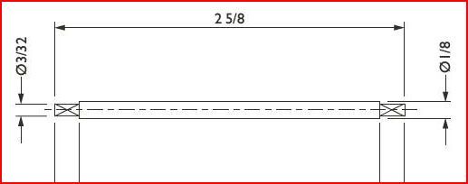
                Neil while you are at it the square ends of the rods have been dimensioned with a diameter symble, may well be the illustrators error or just a quirk of the programme you have used. Text and the way its drawn show it a square.

                Edited By JasonB on 26/02/2013 07:55:58

                #113136
                Ian S C
                Participant
                  @iansc

                  Jason, do you mean the pinion, and Winding Drum Spindles? If you don't want to set up the milling machine, these would only take a few miniutes with a filing rest in the lathe. Ian S C

                  #113155
                  JasonB
                  Moderator
                    @jasonb

                    Ah but how long will it take me to make a filing rest. Still if you think it will allow me to make 3/32nd diameter squares they must be good. wink 2

                    spindle.jpg

                    #113170
                    Anonymous

                      Simple, all that's needed is to square the circle, and then fit the resulting square peg in a round hole.

                      Andrew

                      #113199
                      Sub Mandrel
                      Participant
                        @submandrel

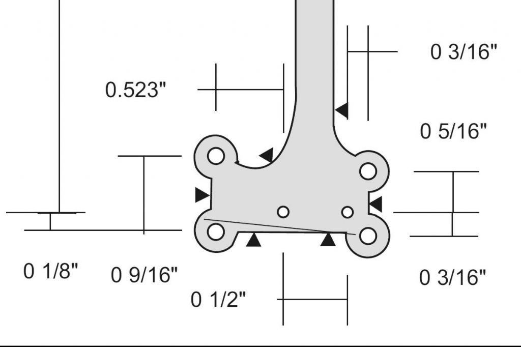
                        Here's a rivised drawing of the lower part of the frame, dimensions taken from the model:

                        revised frame dimensions.jpg

                        You can see my drawing package enters a leading '0' before the fraction – I can't find out how to supress this. I think this is what was interpreted as a diameter symbol when the spindles were redrawn.

                        Another thing to watch is that the lower frame spreader must be made with care to avoid interference with the flanges of the cable/chain drum. the dimension for the flanges seems to have got lost – it should be 3/4".

                        My apologies for the errors – in answer to Paul, all can say is they haven't cost anyone £100, I've made the corrections as quick as I can (I have sent the correction to Diane as well), and if I had to work to industry standards then I and many others would not be able to contribute to the hobby in this way.

                        Please – if any other errors are seen, do speak up.

                        Neil

                      Viewing 10 posts - 1 through 10 (of 10 total)
                      • Please log in to reply to this topic. Registering is free and easy using the links on the menu at the top of this page.

                      Advert

                      Latest Replies

                      Home Forums Model Engineer. Topics

                      Viewing 25 topics - 1 through 25 (of 25 total)
                      Viewing 25 topics - 1 through 25 (of 25 total)

                      View full reply list.

                      Advert

                      Newsletter Sign-up