CAD for beginners

Advert

CAD for beginners

Home Forums CAD – Technical drawing & design CAD for beginners

Viewing 20 posts - 1 through 20 (of 20 total)
  • Author
    Posts
  • #641560
    David Heath
    Participant
      @davidheath77664

      Could anyone recommend an affordable CAD software for beginners

      Advert
      #21412
      David Heath
      Participant
        @davidheath77664

        advice needed

        #641568
        Thor 🇳🇴
        Participant
          @thor

          Hi David,

          If you want to try 3D CAD you might try FreeCAD, Fusion360 has a free version and you might check out Solid Edge CE. It has been discussed on the forum before, a couple of links:

          ***Link***

          ***Link***


          Thor

          Edited By Thor 🇳🇴 on 17/04/2023 07:27:30

          #641569
          Baz
          Participant
            @baz89810

            This subject has been done to death in the last few months, you might be best using the search bar above.

            #641571
            Gary Wooding
            Participant
              @garywooding25363

              Hi David. Because you have also started a thread about 3D printing I assume you want to create 3D model;s for printing.

              There are quite a few CAD systems from which to choose, but no matter what you finally decide on, be prepared for a very steep learning curve. I've tried the three big players: Solidworks, SolidEdge, and Fusion 360, and reckon the easiest one to learn is F360. Solidworks is very expensive and there is no free version, so you will probably skip it. The free version of SolidEdge is very powerful but can be rather difficult to learn. F360 is just as powerful but holds all your models in the cloud. Some people object to this, but it works fine for me. It's very easy to save your models to your own disks, but I don't really see the point. Being in the cloud means that you can access your models from any computer that has installed F360, anywhere in the world.

              I haven't tried any other free system, but, because of the steep learning curves, it's not really practical to to switch.

              Did I mention the steep learning curves? Whatever you choose, be prepared to spend months learning it. You can learn the basics in a few days, but that's just the beginning. Don't despair and give up.

              #641573
              Nealeb
              Participant
                @nealeb

                Do you have any CAD or draughting experience? Do you have access to anyone locally or otherwise who can give you help? Particularly if you are starting with 3D CAD, where some of the concepts and ways of approaching it are not necessarily intuitive, getting some of those initial ways of thinking under your belt would save a whole lot of grief and pain! For evidence, just look at some of the recent threads on the subject…

                As it seems that you want to get started with 3D printing, you are going to need 3D CAD. Personally, I reckon that Fusion 360 has a lot going for it. Very good for 3D printing. I also use Solid Edge but decidedly over the top for 3D printing. There will be plenty of other suggestions; I've only mentioned things I use personally.

                #641578
                IanT
                Participant
                  @iant

                  Hi David,

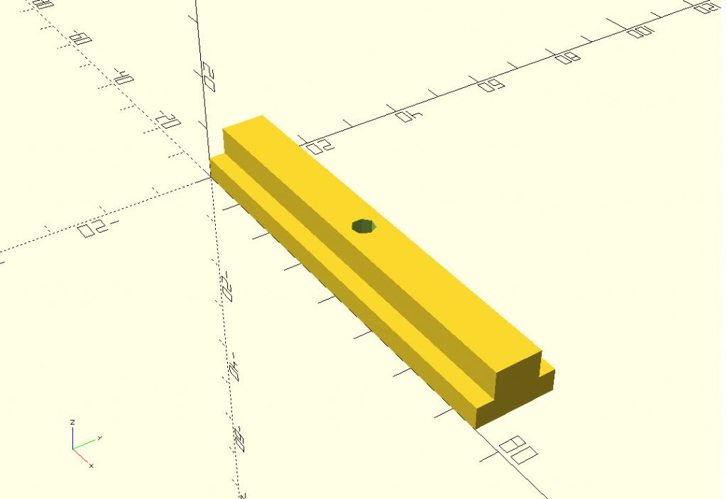
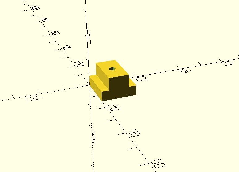
                  When I first purchased a 3D printer, a friend recommended that I use Open SCAD to make the fairly simple 'designs' I needed. It worked very well for me and has a very easy learning curve. You can do complex work with it and I believe it is capable of some things (mathmatically) that would not be possible with traditional CAD. If you have a logical mind then it may suit you. Previous progaramming experience is NOT required. One of the best aspects of SCAD to my mind is that the simple text files can easily be exchanged via cut 'n paste from Forums (including this one) that don't have file system as such. SCADs can also be designed to be customisable (e.g one basic design, many versions). As an example, here is a T-Slot "filler" I designed using Open SCAD

                  t_slot_filler.jpg

                  short_filler.jpg

                  Same 'Code' – different variables. Here's the code, you can just copy it and paste into SCAD

                  //
                  //
                  // T-Slot Filler – IanT
                  //
                  L = 75; // T-Slot Length
                  HR = 1.5; // Hole Radius
                  BW = 14; // Bottom (of Slot) Width
                  TW = 8; // Top (of Slot) Width
                  BH = 4; // Bottom (of Slot) Height
                  TH = 9; // Top (of Slot) Height
                  //
                  //
                  difference () {
                  union () {
                  cube ([L,BW,BH], center=false);
                  translate ([0,(BW/2-TW/2),0])
                  cube ([L,TW,TH]); }
                  translate ([L/2,BW/2,0])
                  cylinder (TH,HR,HR);
                  }

                  You can download SCAD here…

                  Open SCAD

                  I now use Solid Edge which required a great deal more effort to learn than SCAD but I needed dimensioned drawings of some of my work and SCAD doesn't provide them. But for a simple way to get into 3D Print it's brilliant. There are also a lot of useful SCAD desings that you can download (and modify) on Thingiverse.

                  Regards,

                  IanT

                  #641580
                  IanT
                  Participant
                    @iant

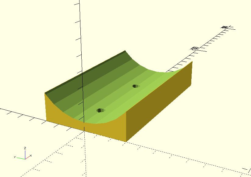
                    Here's another one to try. I purchased a 220V DC motor that didn't have a foot (just two threaded holes) so needed a mounting. This design could be changed to mount any round object on a flat plane though…

                    //
                    //
                    // Sadddle for DC (220V) Motor
                    //
                    // IanT
                    //
                    BL = 107 ; // Base Length
                    BW = 60 ; // Base Width
                    BD = 20 ; // Base Depth
                    ML = 107 ; // Motor Length
                    MR = 39 ; // Motor Radius
                    HD = 25 ; // Hole Depth
                    HR = 3.1 ; // Hole Radius (Clearance)
                    D1 = 20 ; // First Hole Distance
                    D2 = 70 ; // Second hole Distance
                    //
                    difference () {
                    translate ([0, -(BW/2), 0])
                    cube ([BL, BW, BD]) ;
                    translate ([0, 0, (MR + 6)])
                    rotate ([0, 90, 0])
                    cylinder ( ML, MR, MR) ;
                    translate ([D1, 0 ,0 ])
                    cylinder ( HD, HR, HR) ;
                    translate ([D2, 0, 0])
                    cylinder ( HD, HR, HR) ;
                    }

                    dcmotor_saddle.jpg

                    Give it a try, SCAD is good fun and most importantly you can get simple things done on your first evening with it – it's pretty simple to get started with….

                    Regards,

                    IanT

                    #641586
                    JasonB
                    Moderator
                      @jasonb

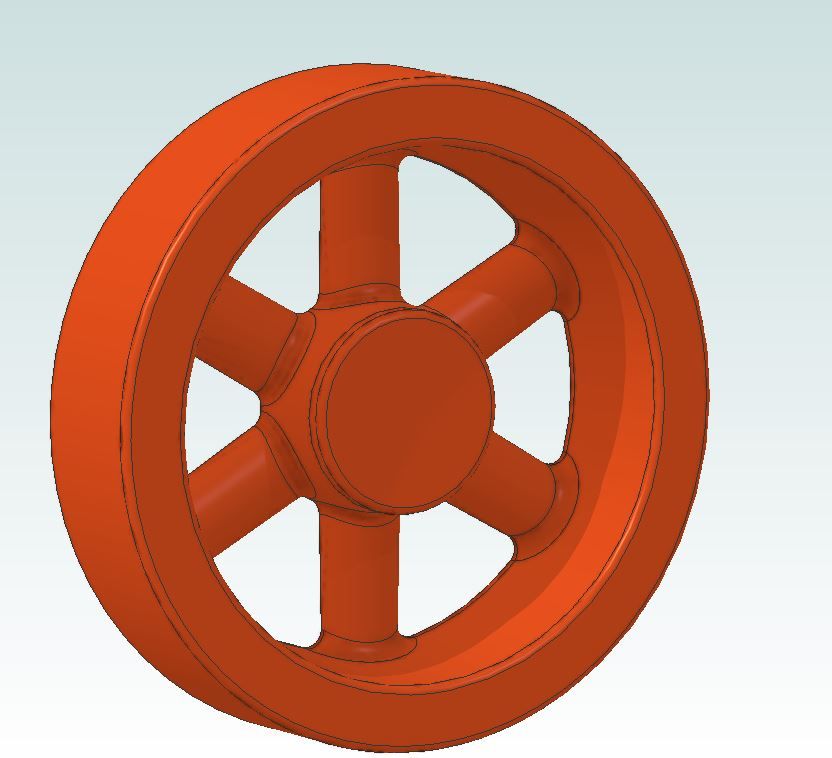
                      As you asked about affordable CAD I's say Alibre's Atom3D, can be had for a one off payment or you can pay for regular updates.

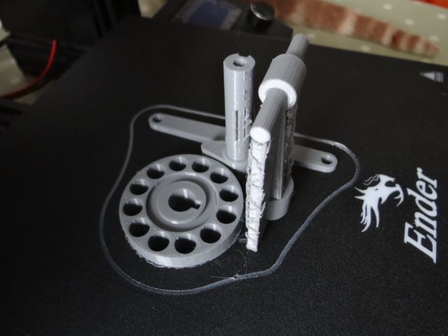
                      Couple of things recently drawn that I shared with people who wanted to print

                      derwing pulley half.jpg

                      redwing print.jpg

                      vic3d.jpg

                      twin vic.jpg

                      #641589
                      SillyOldDuffer
                      Moderator
                        @sillyoldduffer

                        Always best to start with what CAD will be used for by the owner!

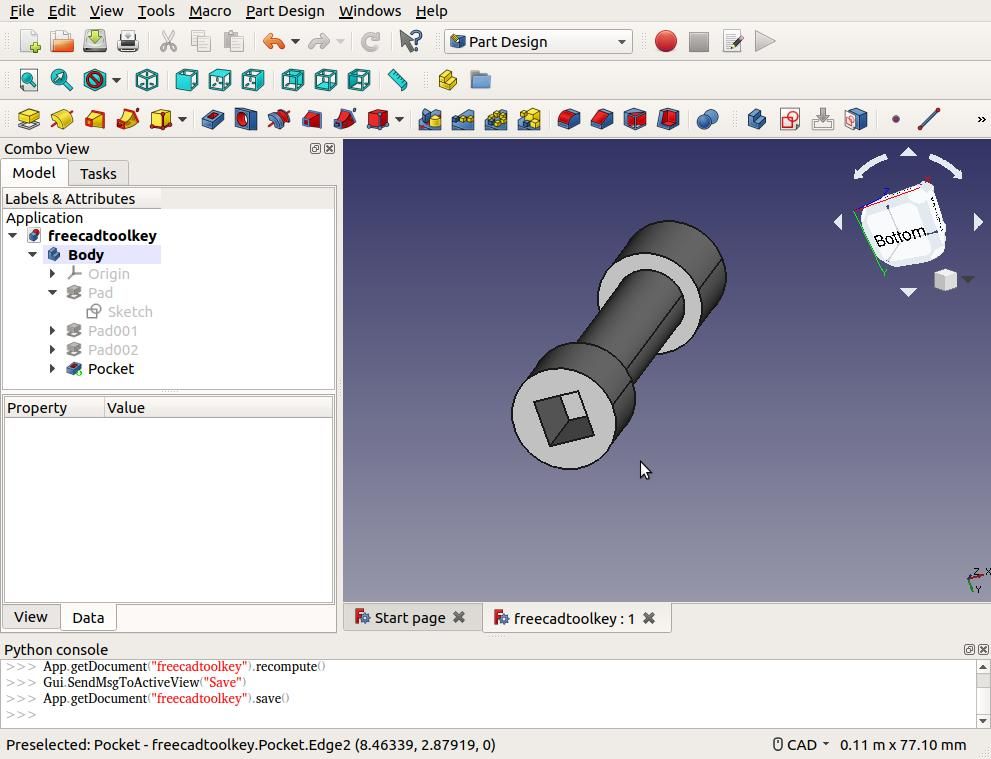
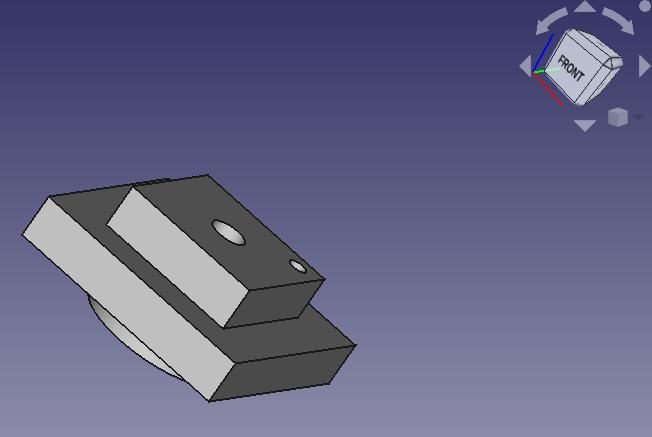
                        For 3D printing and single parts I mostly use FreeCAD, which really is completely free. Downside, it covers a lot of different CAD methods, they're all a bit experimental (crashes occasionally), and not necessarily compatible with each other! However, for 3D printing and Mechanical Engineering the FreeCAD "Parts Design" Workbench works well and does all the basics. I wrote a 'Get Started' thread in 2019 which can be followed to get a feel for how Part Design works without getting entangled with the rest. Good for 'Solid Model' objects like this, which can be metalworked or 3D printed:

                        freecadsquaresocket.jpg

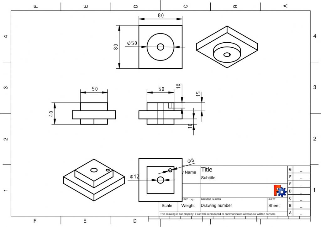
                        FreeCAD also has a Technical Drawing workbench which creates dimensioned first angle or third angle projections from 3D parts: these are important when the part is made manually rather than CNC or 3D-printed/

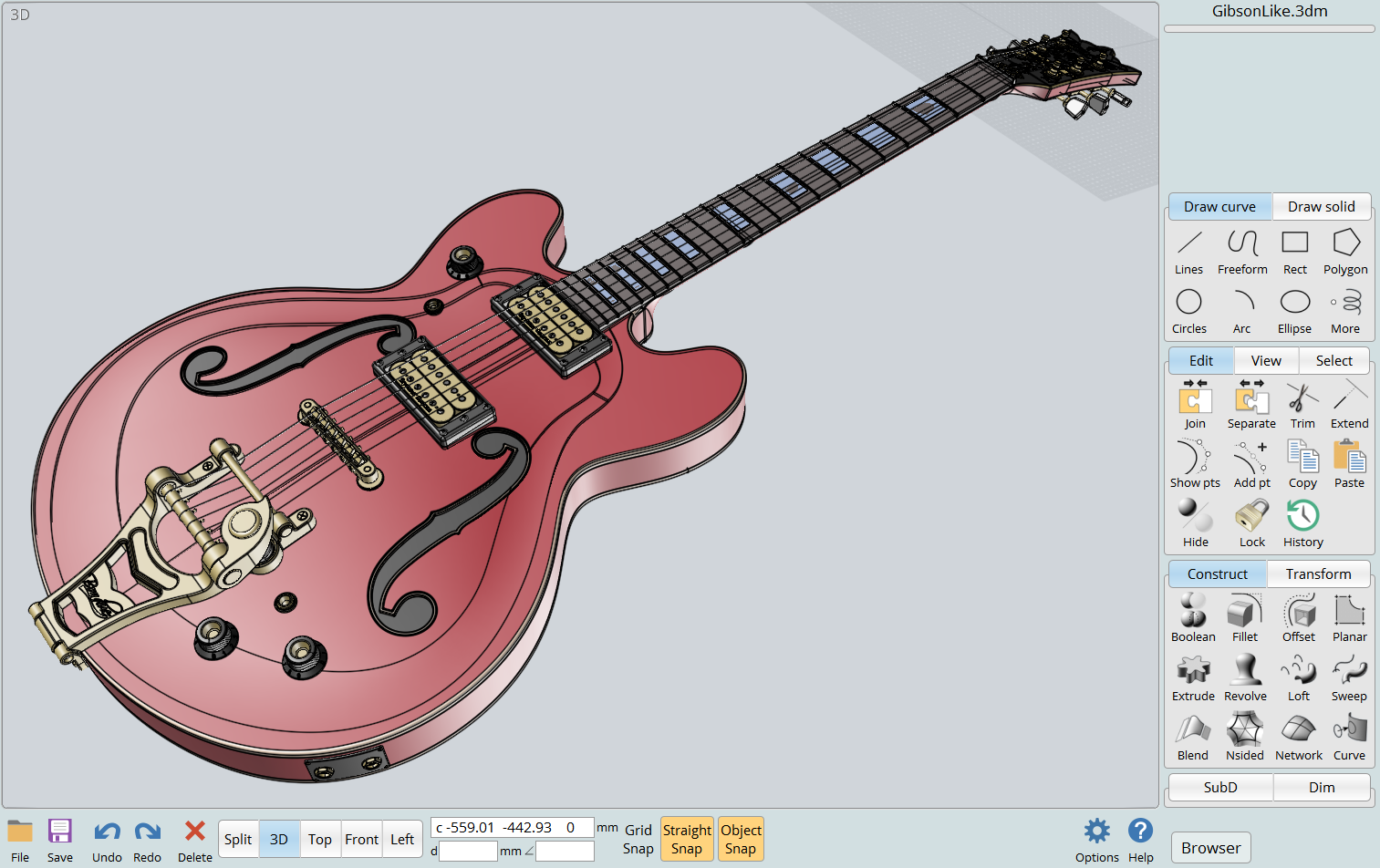
                        Blowlamp has recently drawn our attention to MOI (paid for, not too expensive), which seems fairly easy to drive. (But beware, CAD tools aren't simple.). Judging by Blowlamp's videos MOI can do much the same as FreeCAD Part Bench, but not I think, produce dimensioned technical drawings on paper. MOI has good 'Surface Model' support which is important for producing curvy objects like like this:

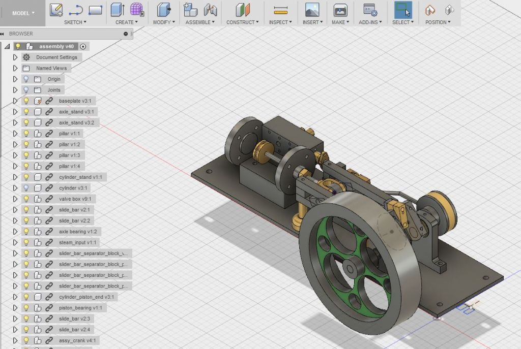
                        Fusion 360 works in a similar way to FreeCAD but is slicker, mostly consistent, and more complete. The completeness includes Assembly, that is models consisting of multiple jointed parts:

                        fusion360_browser_ok.jpg

                        I found it easiest to learn, perhaps because it works in a similar way to FreeCAD, which I already knew. However, Fusion is a cloud product, which has privacy and control implications, for example AutoDesk applied a 10 open file restriction to the hobby version. Not a show-stopper but quite annoying.

                        For that reason I switched to Solid Edge. Like Fusion, SE is also 'full function', able to do Surface Modelling, Sheet-metal, and Assembly, but it's an older product and the interface isn't quite so slick. The product also works in two modes, which is confusing. Ordered Mode is like Fusion and FreeCAD, that is the model is the end result of a step by step history. So if a hole needs to be moved, the operator finds where it was created in the history, alters it, and the change ripples forward through the model. All good unless the new hole breaks something else on the way! Synchronous avoids that by allowing the hole to be moved in the current model: it's very natural. However, it destroys the history, which can cause trouble too. Mostly though, Synchronous is preferred to Ordered, unless it doesn't work! SE works very well, and Synchronous is hot stuff, but I found it harder to learn than Fusion.

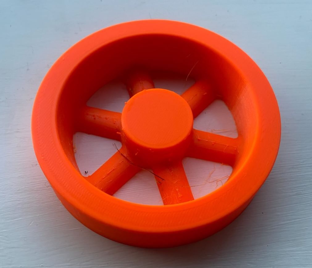
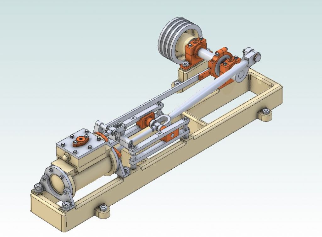
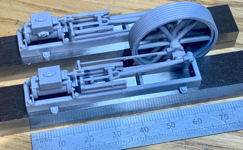
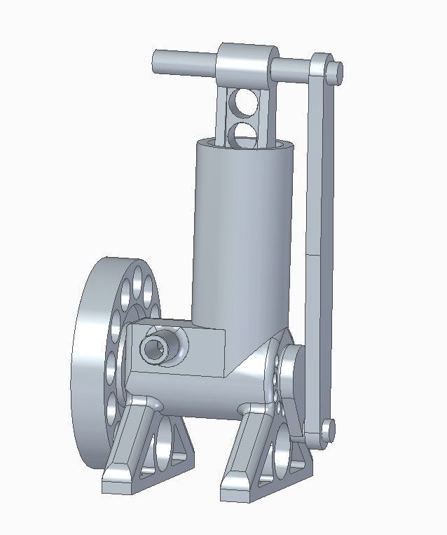
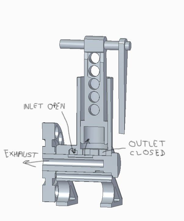
                        This is a 3D-printed engine in SE, an assembly of many individual parts with joint constraints. The model animates without parts colliding, but the real one doesn't because friction is high and the plastic bends. Apply enough compressed air to overcome piston stiction and it twists off the conrod and hits the ceiling. I think a metal version might work.

                        simpleenginefront.jpg

                        simpleenginefrontsectionjustafterbdc.jpg

                        dsc06609.jpg

                        I'd recommend sticking with Fusion, SE, FreeCAD, or Alibre (covered in a MEW series) because several forum members use them and can answer questions.   We have a member struggling with TurboCAD at the moment, and part of his problem is only one other member knows TC well enough to give good answers.

                        Dave


                        Edited By SillyOldDuffer on 17/04/2023 10:00:52

                        Edited By SillyOldDuffer on 17/04/2023 10:05:37

                        #641592
                        lee webster
                        Participant
                          @leewebster72680

                          I am not too sure if this is still true, but there used to be a "student" version of Solidworks. When I started out in the world of cad about three years ago I sent Solidedge a cheeky email asking if they had a hobby version I wouldn't have to pay for. They emailed back saying yes! I had a link to where I could download the software from and they also emailed me the code to activate it. My computer failed on the download, so I emailed them to say I would have to give it a miss because of the download speeds in my area. Their reply was "no problem, give us your home address and we'll send you the installation discs". Less than a week later the DVDs turned up all the way from America. I installed and used the software for several months before I began to wonder what would happen if they pulled the plug at some point. That's when I turned to FreeCAD, and then to Design Spark Mechanical. Both free. I do miss Solidworks though. I still have the DVDs in case I can re-install one day.

                          #641599
                          Ady1
                          Participant
                            @ady1

                            Our main Alibre thread is here

                            Various other threads too

                            #641605
                            Bazyle
                            Participant
                              @bazyle

                              I recommend you at least start by looking at SillyoldDuffer's (SOD) tutorial he linked above as it is free and a gentle introduction.
                              One thing that frightens people about FreeCad is that there are lots of 'workbenches' that seem like there are lots of different programmes. However actually there is just the one programme and the workbenches are only different sets of toolbars being displayed for convenience because an architect wants different tools to an engineer. You can actually customise the display to add or subtract those toolbars if you wish but it is easier to just click to flip to a different workbench for a few minutes and back again. It doesn't hurt your drawing.

                              #641609
                              John Doe 2
                              Participant
                                @johndoe2

                                I use Shapr3D because I wanted something to run on an Apple iMac or iPad – most of the other CADs are Windows only.

                                Shapr3D is good for quickly drawing a shape to be 3D printed. I am still a CAD beginner so I don't know how it gets on with models with interacting parts, e.g. axles or hinges.


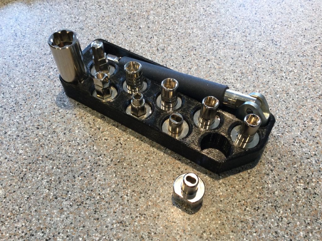
                                Plumbing tool holder:

                                image.jpg


                                Edited By John Doe 2 on 17/04/2023 11:09:18

                                #641615
                                blowlamp
                                Participant
                                  @blowlamp

                                  Dave.

                                  MoI does have dimensions. You can't print directly from MoI, but you can save to a PDF and print from there, as I've shown in the video.

                                  Martin.

                                  #641619
                                  blowlamp
                                  Participant
                                    @blowlamp

                                    The more unusual, but versatile, Rail Revolve tool in MoI.

                                    Martin.

                                    #641634
                                    SillyOldDuffer
                                    Moderator
                                      @sillyoldduffer
                                      Posted by blowlamp on 17/04/2023 11:40:39:

                                      Dave.

                                      MoI does have dimensions….

                                      Martin.

                                      It does, but not on technical drawings generated from the solid. (I believe?) Say I create a 3D object like the base of a 4-way tool-post:

                                      4way3d.jpg

                                      And I want a formal First Angle or Third Angle drawing so a machinist can make it:

                                      4waytp.jpg

                                      The 2D-CAD drawing is automatically generated from the 3D model, using a template with a title block and other control goodies.

                                      It's drawn to scale and because the Techdraw workbench 'knows' what all the 3D dimensions are, the user can add them to best effect by clicking on lines or points etc. The workbench can also do sections, details, balloon annotations and cosmetic stuff.

                                      MOI isn't a good choice if producing formal 2D projections is important. But it's true that for many purposes labelling the 3D object as demonstrated in your video is 'good enough'. Fusion, SE and Alibre can also generate formal 2D technical drawings.

                                      Dave

                                      #641645
                                      blowlamp
                                      Participant
                                        @blowlamp

                                        Dave.

                                        I don't think MoI is aimed at being a complete drawing office. It's designed to be as easy and as fluid as possible to use, without a huge learning curve. It doesn't have assemblies, constraints, or auto dimension, but it is pretty straightforward to use and will make drawings every bit as precise as any other CAD we are likely to use. MoI also has a few tools that allow it to do things that other CAD apps struggle with. Its primary focus is to create the drawing model, as it is always possible to export to another app for added tweaks.

                                        Martin.

                                        #641655
                                        Peter Cook 6
                                        Participant
                                          @petercook6

                                          Another +1 for MoI. I don't have a technical drawing background and found my brain simply did not get on with the "standard" CAD software paradigms.

                                          MoI I found very easy and intuitive, and is excellent for creating models for 3D printing. I do use blowlamp's approach (PDF's) to produce hard copy to take to the workshop, but I only draw on the dimensions I want rather than producing formal third angle drawings – which I struggle to read anyway.

                                          #641663
                                          Gary Wooding
                                          Participant
                                            @garywooding25363

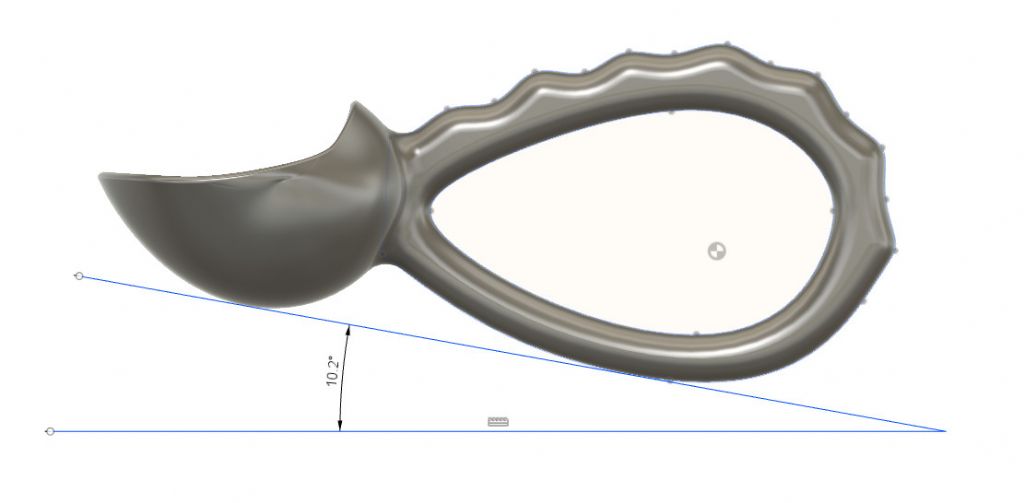
                                            Just one plus point for F360. It has a facility called T-Splines, which is, as far as I know, unique to F360. It allows you to create non-planar 3D surfaces which are easily converted into solid models. A T-Spline is rather like a linear spline, but applied to a surface rather than a line. This can be very useful for creating creating complex shapes such as these..

                                            tilt angle loop.jpgtilt angle.jpg

                                          Viewing 20 posts - 1 through 20 (of 20 total)
                                          • Please log in to reply to this topic. Registering is free and easy using the links on the menu at the top of this page.

                                          Advert

                                          Latest Replies

                                          Viewing 25 topics - 1 through 25 (of 25 total)
                                          Viewing 25 topics - 1 through 25 (of 25 total)

                                          View full reply list.

                                          Advert

                                          Newsletter Sign-up