Buzz Coil Condenser/capacitor

Advert

Buzz Coil Condenser/capacitor

Home Forums I/C Engines Buzz Coil Condenser/capacitor

Viewing 25 posts - 26 through 50 (of 53 total)
  • Author
    Posts
  • #95032
    jason udall
    Participant
      @jasonudall57142

      Much as the Analysis / Synthesis is facinating.( I mean it) , the OP might in reality be limited to using the "suppressor" cap seen across automotive points..( heaven knows what the working voltage and cap.is.. not to mention ESR) and the question is " Is one enough? Or should we use two?"

      ….

      Advert
      #95040
      JasonB
      Moderator
        @jasonb

        Well its good to see that my question has got you all rattling the grey matter even if most of it is all a bit over my head.

        I've not got a condenser for a Tecumseh mower (just the one) and am just waiting for some cotton braided HT cable which will look the part then I will make up a test circuit to see how things go before making a scale looking box for all the gubbins.

        Andrew with luck I'll have it on a working engine if you are going to be at Stratfield next month, bring your oscilascope if you want to see the wave patternwink 2

        J

        Edited By JasonB on 24/07/2012 14:55:24

        #95069
        Martin W
        Participant
          @martinw

          Hi Andrew

          Like what you have done to date as it puts a different perspective on things. I have been cogitating on this and realise it is not simply a case of points closing/opening etc. So I have a new take on this and it takes on board some of what you have said and some of my bits as well, couldn't leave them out could I wink 2.

          It goes like this:

          Initially ignoring the HT winding

          a. Points are closed and the current flowing through the LT, low tension coil, generates a magnetic flux in the core; its assumed that the core is not saturated at this stage.

          b. Points open and the capacitor in its discharged state is effectively connected between the LT coil and earth. The capacitor charges and draws more current through the LT coil increasing the magnetic flux. The LC product sets the effective resonant frequency of this combination, see Andrew's posts and graphs, and this effectively dictates the rise time of the charging pulse i.e low value capacitor fast rise and higher value capacitor lower rise time.

          c. The value of the capacitor has another effect and this is the Q.This is not the same Q that Andrew refers to in his post but as in Q=CV in coulombs. This can, after a bit of integration, be described in W watts or available energy.

          d. Bringing the HT winding back into the equation. The HT winding is mounted on the same core as the LT winding and so is affected by this increase in field flux. When the flux increases the HT coils generates a voltage in response to this and I think that this voltage will be dependant on the rate of change of flux that the coil is subjected to, my original argument smiley regarding V=dv/dt x h.

          If the capacitor has to small value then although the rise time will be fast there will not be enough energy Q=CV either to maintain or even initiate the ionisation of the spark gap, conversely if the capacitor value is to high then while there is plenty of energy the rise time will be too slow to generate the required voltage to initiate ionisation.

          The graph in the article I referred to shows the initial spike when the contacts open, similar to that in Andrew's simulation, followed by a relatively low voltage plateau during the spark burn time. I think that the near constant voltage across the capacitor is when the capacitor is charging and drawing current through the LT winding to maintain flux change required to sustain the ionisation.

          This may be wildly out but seems fairly logical after a couple of glasses of red wine supped in the garden on a rare warm evening.

          Looking forward to the results of Andrew tests.

          Cheers

          Martin

          Edited By Martin W on 25/07/2012 00:35:07

          #95081
          Les Jones 1
          Participant
            @lesjones1

            Hi Martin,
            I do not agree with your theory that the available energy for the spark is related to energy storage in the capacitor. The energy is stored in the coil. It will be 0.5 x L x I squared. L is the inductance of the primary of the coil and I the current through the primary of the coil just before the contacts open. At low speeds this current will be limited by the resistance of the coil. At higher speeds it will be limited by the time the contacts are closed.

            Les.

            #95084
            Martin W
            Participant
              @martinw

              Hi Les

              My logic, if that is the right word to use, for the energy in the spark being a function of the capacitor value is that when the points are opened the earth end of the coil is connected to the capacitor in its discharged state. This causes current to flow into the capacitor via the LT winding. My thought is that this will then increase the magnetic flux and this will induce the high voltage on the HT winding. The amount of current/energy, mixed terms I know, is determined by the value of the capacitor and the effective voltage it is exposed to hence my supposition that it is dependant on Q=CV. I totally agree with you that there will be quite a lot of energy stored in the coil windings but I was looking for a reason why the circuit only works within a fairly narrow band of capacitor values.

              As I said I might be wildly off but the nice thing about this forum is that one can put forward ideas and they will reviewed and commented on in a civilised manner.

              Cheers

              Martin

              #95085
              Donhe7
              Participant
                @donhe7

                Without going into too much detail, I seem to recall in some automotive tome, the capacitor (condenser, in their parlance), was chosen in value/design, to resonate with the coil and points circuit, and also to quench the spark at the points, and the value was specified by the particular vehicle/engine, to which it was fitted, also, in some cases, the "supressor condenser",(!) was to be removed, in some cases when a different coil was fitted.

                donhe7

                #95105
                Russell Eberhardt
                Participant
                  @russelleberhardt48058

                  Martin,

                  Think about it like this:

                  The spark occurs when the points open. At this point in the cycle the capacitor voltage has been held at zero by the closed points so it has no stored energy. On the other hand, the inductor is passing a high current through the points and thus has energy stored in its magnetic flux. It is this ebergy that creates the spark. The main purpose of the capacitor is to restrict the rate of voltage increase across the points and prevent arcing across the points.

                  Hope that helps.

                  Russell.

                  #95110
                  Sub Mandrel
                  Participant
                    @submandrel

                    Russell's is the simplest and most apt explanation – the 'condensor' (as they are still known in this unique application) is to protect the points.

                    By stopping the cessation of current flow in the primary being instantaneous, it actually slightly weakens the spark – so it should not be too large, just big enough to stop the voltage across the poins rising enough to spark.

                    Neil

                    #95112
                    Martin W
                    Participant
                      @martinw

                      Hi Russell

                      I totally agree with you that immediately prior to the points opening the capacitor has zero volts across it, terminals shorted by the points, and the LT coil will be running at near max current with a field established.

                      However when the points open the capacitor, in its discharged state is effectively switched in between the the -ve end of the coil and earth. At this point the capacitor will start to charge and the only way this can happen is for current to flow through the LT winding. The effect of switching the capacitor into circuit can be seen on the simulation generated by Andrew, no HT coil loading simulated, where there is an initial voltage spike followed by a decaying sinusoid as the circuit goes into a damped oscillation. The first part of the waveform is very similar to the recorded waveform from an actual circuit in action. The mid and latter stages are naturally quite different where there is the level voltage plateau of about 40V across the capacitor during the spark burn ending when the energy is used up and the spark dies and there are a couple of low frequency cycles. The fact that this voltage remains fairly constant during this phase of the cycle when there is a relatively large amount of energy being dissipated in the spark intrigues me

                      The fact that if the capacitor is too low in value the spark is weak or non existent and if too large there is no spark make me think that the capacitor has a more complex role in the circuit other than just suppressing the contact arc problems.

                      I may be over-complicating things but I am keen to know the whole story. Someone sort it out cause at 69 me grey cells are getting far apart and few between.

                      Cheers

                      Martin

                      #95135
                      Russell Eberhardt
                      Participant
                        @russelleberhardt48058

                        Hi Martin,

                        My point was that it is the energy stored in the inductor that creates the spark. Before the contact breaker opening the capacitor has no stored energy. What you are seeing in Andrew's simulation is the energy being transfered back and forth between the inductor and the capacitor after the points open.

                        He has not simulated the spark gap so no energy is lost in the spark and the ringing continues with losses, mainly in the inductor, absorbing some of the energy on each cycle.

                        I no longer have Spice installed on my computer so can't show you a fuller simulation but if Andrew wants to continue he will find a simple model for a spark gap here.  In practice it is more complicated as the spark gap displays negative resistance when the discharge starts.

                        I'm afraid my grey cells are getting a bit sparse as wellfrown

                        Regards

                        Russell.


                        Edited By Russell Eberhardt on 26/07/2012 10:09:18

                        Edited By Russell Eberhardt on 26/07/2012 10:17:43

                        #95171
                        Anonymous

                          Jason: If I make it to Stratfield I'll be sure to bring my oscilloscope and high voltage probe; which is almost bigger than the 'scope!

                          I agree that the energy in the coil at the point at which the contacts open is (1/2)*L*I**2. Once the contacts open we have a series resonant circuit, so all of the energy will transfer to the capacitor, and then back to the inductor and so on. The energy stored in the capacitor is (1/2)*C*V**2. In this sense the value of the capacitance determines the peak voltage swing, which is what we're after. Here I disagree with Russell; the stored energy does not cause the spark, it's the induced voltage in the secondary that creates a spark. Once the spark is formed and a current flows, then the stored energy is transferred to the spark, and that energy is what ignites the air/fuel ratio. Think Van der Graff generators, these produce pretty impressive sparks by generating high voltages, but very little energy is involved. There are two different parameters at work, one the voltage needed to breakdown the spark gap in the first place, and second the amount of energy needed to ignite the mixture once a plasma has formed in the spark gap. As a first approximation they are not related.

                          I agree that the capacitor reduces, or eliminates, sparking on the contact points, but it has a second, equally important, role. Since the capacitor has prevented contact sparking by stopping the rapid collapse of the magnetic field in the inductor we need another way to generate a high voltage to cause the spark gap to breakdown. The capacitor provides this by resonanting with the inductor, creating peak voltages that can be many times the supply voltage. Think here Tesla coils where very high voltages are induced on a secondary winding by using two loosely coupled tuned circuits to generate voltages much higher than might be supposed by just looking at the supply voltage and turns ratio.

                          Of course all bets are off once we have a secondary winding and spark gap. When time permits I'll try replacing the inductor by a transformer in the simulation.

                          Regards,

                          Andrew

                          #95173
                          Jeff Dayman
                          Participant
                            @jeffdayman43397

                            I am not knowledgeable about all this electronic theory, and the only thing I know about silly-scopes is you can rest tea mugs and books on the housing,cool but here's one practical bit of info from actual experience, offered as food for thought:

                            When the condensor "goes bad" or shorts out on a points based car or mower ignition, usually the engine still runs fine. Spark at the plugs is obviously adequate if not optimal, and basic ignition timing is unaffected. The points will pit and eventually burn though, in this state. My conclusion based on observed actual engines is that a working condensor extends the life of the points ignition system but is not critical for basic operation.

                            JD

                            Edited By Jeff Dayman on 26/07/2012 22:31:43

                            #95180
                            Anonymous

                              Jeff: Errr, if the capacitor goes short then the circuit will not work at all. Operating the points with a short across them will have………no effect! If, however, the capacitor goes open circuit then I agree that the circuit will continue to operate. Removing the capacitor changes the way the circuit works. So your conclusion that the capacitor is not critical for basic operation is not correct, as removing the capacitor changes the basic operation of the circuit even if the end result (a spark) is the same. There, that's another hair split.

                              Generally capacitors do not fail short, at least not for long, with the exception of tantalum capacitors, which nearly always fail short. I hate 'em!

                              Regards,

                              Andrew

                              #95194
                              Russell Eberhardt
                              Participant
                                @russelleberhardt48058
                                Posted by Andrew Johnston on 26/07/2012 21:43:53:Here I disagree with Russell; the stored energy does not cause the spark, it's the induced voltage in the secondary that creates a spark.

                                I think we are saying the same thing. Yes, of course it's the induced voltage in the secondary that starts the spark but what causes that induced voltage? The collapsing flux in the core in which the energy is stored.

                                As an aside, does anyone remember the fashion for capacitor discharge ignition in the 1970s? In those systems the energy was stored in the capacitor but to get enough energy stored it had to be charged to a high voltage by an inverter. I built one to a design published in "Wireless World". They had the advantage that the charging time was shorter and so would work at higher revs. I believe that they are still used on some small engines – perhaps that system could be usefull for models as they can be made more compact.

                                Russell

                                #95205
                                JasonB
                                Moderator
                                  @jasonb

                                  The DCI units are quite common on model spark ignition engines, I have a couple of them that are triggered by a Hall Effect sensor though they can be made to work with points. There are also a lot of RC model 4 strokes that use them. These ones are quite good

                                  I didn't want to go down the CDI route with this engien as it has the scale timer & contacts plus adding a ring to take the magnet for teh hall effect would have spoilt the model.

                                  J

                                  Edited By JasonB on 27/07/2012 12:27:47

                                  Edited By JasonB on 27/07/2012 12:30:01

                                  #95211
                                  Anonymous

                                    Jason: Neat units, but they seem remarkably cheap for what I understand a capacitor discharge ignition to be. Normally a capacitor is charged to high voltage (usually 400-600V) and then discharged through an ignition coil in the normal configuration. They're doing pretty well to include a boost converter at that price! May be it just charges a capacitor up to the battery voltage?

                                    Regards,

                                    Andrew

                                    #95216
                                    JasonB
                                    Moderator
                                      @jasonb

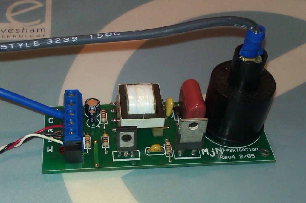
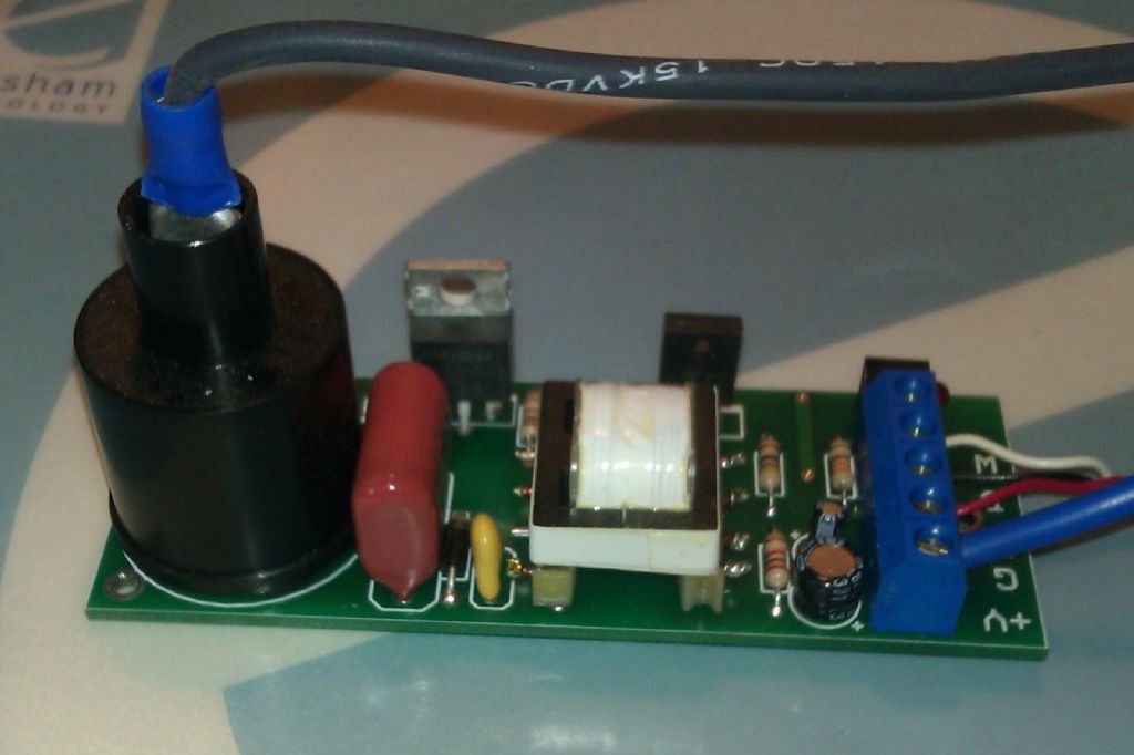
                                      Andrew, here are a couple of photos of teh unit I got from MJN Fabrications in teh states, as its not in a case you can hopefully work out what does what. Black wire goes to plug, blue is ground and there is a positive terminal next to that for battery, the 3 small wires are the hall sensor. Click to get them bigger.

                                      imag0754.jpg

                                      imag0753.jpg

                                      J

                                      PS these units give a single spark unlike the buzz coil that gives a stream of sparks all the while that the timer is making the circuit so you get a much longer period of ignition.

                                      #95300
                                      Anonymous

                                        Jason: Thanks for posting the pictures. As far as I can see the circuit is a pukka capacitor discharge ignition system. It's a pretty elegant piece of design; clearly done by somebody who knows his volts and amps.

                                        Here's an annotated copy of one of Jason's pictures, identifying the various parts:

                                        358276.jpg

                                        From the left, the input filter capacitors provide some filtering for the incoming DC supply. I assume that the LED indicates when firing occurs. One of the resistors marked 'Rs' is probably associated with the LED as a current limit. Together the transistor and transformer make what I assume is a blocking oscillator. This uses an auxilliary winding on the transformer to provide the positive feedback necessary to create an oscillator. One of the resistors 'Rs' will be to initially kick start the oscillator when power is applied. The transformer will have a third, step up, winding to provide a high voltage AC output. This is rectfied by the diode and feeds the high voltage capacitor with DC. I assume that the small yellow filter capacitor near the high voltage capacitor is to control RF emissions. The coil is obvious, and the SCR (silicon controlled rectifier) is triggered to complete the circuit, discharging the high voltage capacitor into the coil. I assume that the SCR is a logic level device, and can be driven direct from the hall effect sensor. The resistor and capacitor 'RC- gate' are to provide a pull down on the SCR gate to ensure no mis-triggering, or triggering on noise, of the SCR. All in all a pretty neat circuit.

                                        Here's an interesting link detailing the pros and cons of CDI. **LINK**

                                        Regards,

                                        Andrew

                                        Edited By Andrew Johnston on 28/07/2012 22:18:40

                                        #95312
                                        JasonB
                                        Moderator
                                          @jasonb

                                          Thanks for the insight Andrew.

                                          J

                                          #95319
                                          Russell Eberhardt
                                          Participant
                                            @russelleberhardt48058
                                            Here's an interesting link detailing the pros and cons of CDI. **LINK**

                                            Good write-up and interesting site. Hope they win today!

                                            Russell.

                                            #95321
                                            MICHAEL WILLIAMS
                                            Participant
                                              @michaelwilliams41215

                                              The collective explanations for the working of the buzz coil system and the action of the capacitor are no doubt essentially correct – it is after all only a school lab induction coil .

                                              I have however seen an alternative explanation for the presence of the capacitor and that it is there to protect the battery from voltage spikes which could cause rapid degeneration of the plates .

                                              It is a matter of observation that when an industrial actuator solenoid is connected and disconnected from a power source (experimentally) using bare wire ends there can be a vicious spark on disconnect and enough voltage to give a shock to anyone touching both connections to coil at same time .

                                              #95322
                                              Ian S C
                                              Participant
                                                @iansc

                                                Michael, your last paragraph discribes the action of a primary spark system that instead of a spark plug uses an ignighter with a moveing contact inside the engine's cylinder. Some of the vinage engine enthusiasts here use fluro balast coils for this type of ignition. Ian S C

                                                #95323
                                                JasonB
                                                Moderator
                                                  @jasonb

                                                  Yes I ran my IHC famous model off an old lighting Balast with ignitor. You can just see the balast to rthe right of the engine (top of frame) on this video


                                                  J

                                                  Edited By JasonB on 29/07/2012 11:02:02

                                                  #95326
                                                  JasonB
                                                  Moderator
                                                    @jasonb

                                                    IT's BUZZZZZZINGnerd

                                                    Just did a rough and ready lash up to see if it worked and I'm just touching the negative battery terminal with teh wire to simulate the timer on the engine which is basically a switch on the geared down side shaft that drives the cam.

                                                    I'll post some pics later but that will have to wait until the F1 and ladies road race have finished
                                                    #95352
                                                    JasonB
                                                    Moderator
                                                      @jasonb

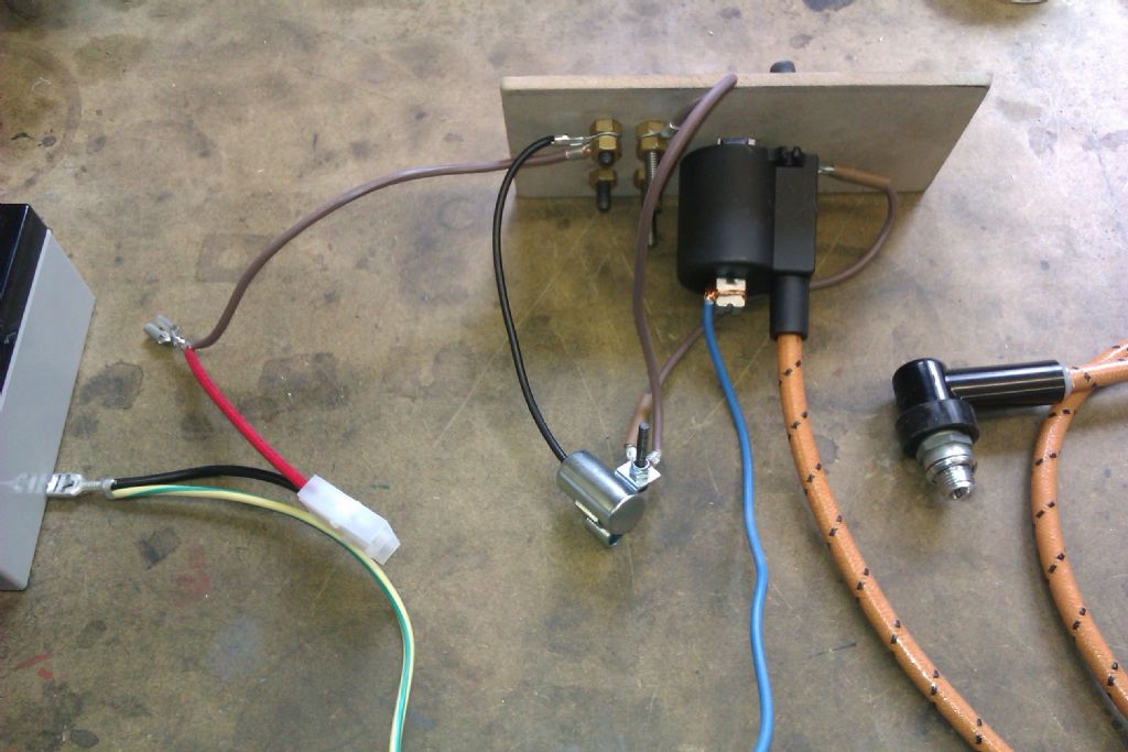
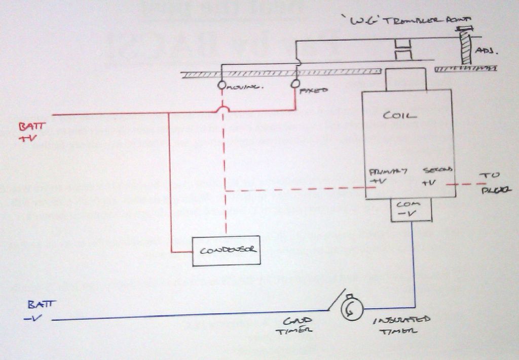
                                                      As promised this is how I made the plug spark, all a bit rough and ready but at least I know it works so can now condense it all down to fit into a nice little wooden box. Green goes to the grounded timer contact on the engine and blue to the insulated contact.

                                                      buzz circuit.jpg

                                                      This is the scematic of what connects to what. I will also add a switch into the positive feed from the battery so it can easily be turned off and there is no risk of it starting to buzz unintensionally if the timer on the engine makes contact.

                                                      buzz schematic.jpg

                                                      Parts used

                                                      6V sealed lead acid battery from e-bay inc charger and RC type socket

                                                      Condenser from Tecumseh mower again e-bay chose this as B&S didn't have the wire fitted

                                                      WG trembler coil points from Engineers Emporium ref TCP1

                                                      12V Mini HT coil again from Engineers Emporium but plenty on the net, just get one with the soft iron core through it.

                                                      Braided & lacquered HT cable and Plug Cap Green Sparkplug Co

                                                      If anybody knows a source for the braided and lacquered HT cable in sizes smaller than the standard 7mm please let me know, plenty of smaller PVC about but can't find braided.

                                                      J

                                                      Edited By JasonB on 29/07/2012 17:47:53

                                                    Viewing 25 posts - 26 through 50 (of 53 total)
                                                    • Please log in to reply to this topic. Registering is free and easy using the links on the menu at the top of this page.

                                                    Advert

                                                    Latest Replies

                                                    Home Forums I/C Engines Topics

                                                    Viewing 25 topics - 1 through 25 (of 25 total)
                                                    Viewing 25 topics - 1 through 25 (of 25 total)

                                                    View full reply list.

                                                    Advert

                                                    Newsletter Sign-up