Buzz Coil Condenser/capacitor

Advert

Buzz Coil Condenser/capacitor

Home Forums I/C Engines Buzz Coil Condenser/capacitor

Viewing 25 posts - 1 through 25 (of 53 total)
  • Author
    Posts
  • #94868
    JasonB
    Moderator
      @jasonb

      I have got most of the parts to make a buzz coil – KW point and a suitable coil, just wondering what size condenser/capacitor to use.

      There seems to be very little on the net about whats inside the boxes but plenty on how to wire them to the engine, best I could find was this article . The engine has a suitable timer with facility to advance & retard the spark, it will be 6volt and uses a CM-6 10mm plug.

      J

      Advert
      #2342
      JasonB
      Moderator
        @jasonb
        #94870
        jason udall
        Participant
          @jasonudall57142

          Ok first I know nothing about "buzz coils".

          that said .

          the capacitor/ condensor stores energy to provide the spark.. thus the bigger the better.. oh hold on this is engineering ..NOT quite that simple..

          Too bigger cap. and it wont reach full voltage on charging cycle ; too small and you are wasting capacity (sorry pun). .

          charge time would crudely be 5 * R *C R being the dc resistance of your charging coil. C being the value under consideration so the charge time at MAX rpm would be ?

          T= 5RC

          thus

          C= T/(5R)..

          Hope this helps

          #94873
          jason udall
          Participant
            @jasonudall57142

            Ok a seconds research shoots all the above down (sort of).

            Looks like the cap is to protect the points more that any more "critical" function..

            but again too much will reduce spark.

            #94875
            KWIL
            Participant
              @kwil

              Jason,

              I would start with a 0.01micro farad and watch that the sparking across the gap is "small" it is all a little subjective I am afraid.

              K

              #94878
              Martin W
              Participant
                @martinw

                Hi

                Just done a dig about and the figure I came up with is between 0.1 to 0.5 uF (micro farads), sometimes listed as 100 to 500 nF (nano farads) but this can depend on the coil being used. The only common ground is that they need to be rated at a fairly high working voltage probably 300-400V DC as a minimum. This is not so much related to the output voltage of the system but the voltage likely to be developed across the primary winding which is a function of rate of current change, when the contacts either make or break, and inductance of the winding; something like e = L x di/dt where L is inductance in Henries, di/dt rate of change of current flow and e is the generated voltage.

                Sorry not to be much help but will keep my eyes open unless you get a definitive answer in the meantime.

                Cheers

                Martin

                #94881
                Russell Eberhardt
                Participant
                  @russelleberhardt48058

                  Why are you using a "buzz coil" as opposed to a conventional contact breaker system. I thought buzz coils (or trembler coils) went out with the model T Ford.

                  Russell.

                  #94883
                  JasonB
                  Moderator
                    @jasonb

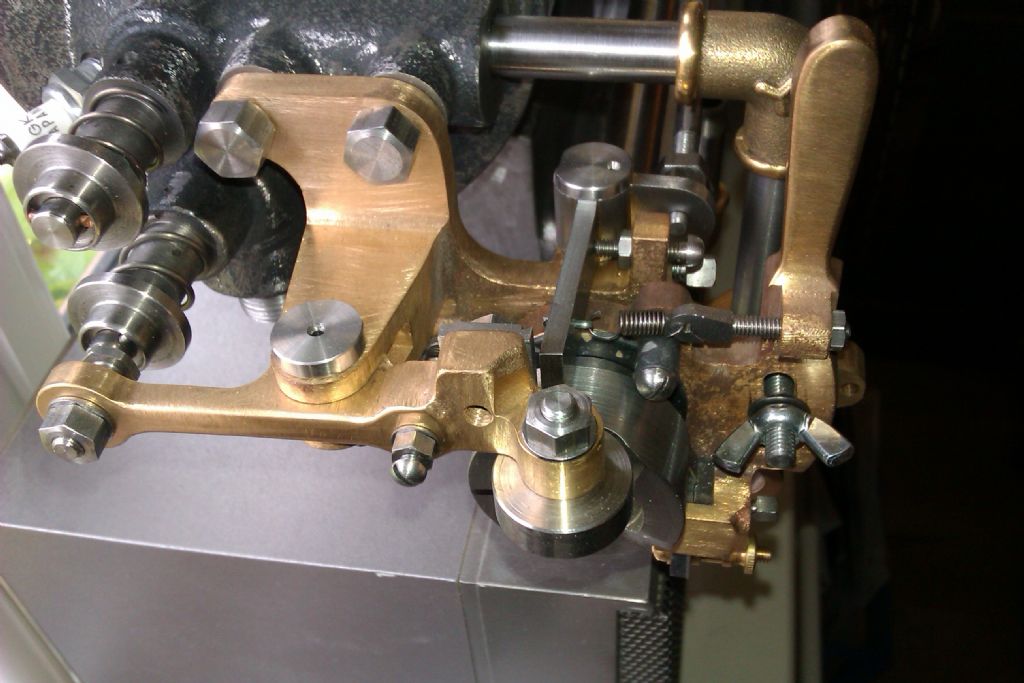
                    Well seeing as the engine that its going to be used on is dated around the same time as a Model T the buzz coil is the ideal choice. As I said the engine also has the correct timer so that it can be advanced or retarded and a contact so the spark is not energized when its "missing" so saving the battery as it only sparks when "hitting"

                    imag0690.jpg


                    I would hate to spoil the correct look of the engine by fitting contact breaker points or waste all those other parts by fitting a hall effect sensor and CDI system. This sort of thing is just as bad as people of fit spark plugs to engines that would have had ignitors just to make their lives easier.


                    J


                    Edited By JasonB on 20/07/2012 17:14:10

                    #94884
                    JasonB
                    Moderator
                      @jasonb

                      Thanks Martin and others, its also been said on another forum that 0.2uf is whats needed and a suitable supression capacitor from CPC suggested to me.

                      Another option is a condenser from something like a Briggs & stratton engine and this seems to be the type shown in teh link I posted above and also on another schematic that I have been sent so may go down that route.

                      You may also be interested in these two videos that show a buzz coil made using a relay rather than teh traditional points and magnetic field of teh coil, it also looks to be using a B&S type condenser. It looks a compact solution but not sure how long the relay would put up with the constant on/off buzzing?

                      **LINK**

                      **LINK**

                      J

                      #94887
                      Martin W
                      Participant
                        @martinw

                        Jason

                        If you don't want to use a relay it may be possible to use a 555 timer IC in free run, astable mode, driving something like a hexfet transistor to drive the coil. Its the sort of thing that can be used in high voltage generators which in reality is what a buzz coil system is. I might have a play around with it as I have most of the parts kicking around I think.

                        Cheers

                        Martin

                        PS

                        555 timer chip can be controlled from your current timing system by connecting this to the inhibit/reset pin.

                        Edited By Martin W on 20/07/2012 18:26:20

                        #94889
                        Jeff Dayman
                        Participant
                          @jeffdayman43397

                          Hi Jason,

                          Any condensor from a small engine, ie mower, chainsaw, string trimmer etc will probably work fine and won't break the bank. The spec is not critical, as others have mentioned the condensor/capacitor is primarily there to keep the points from burning. Specs from my various small engine manuals say most small engine condensors are rated 0.4 to 0.6 micro Farads at 300 to 350 V.

                          As mentioned before, for use on a hot engine a condensor specifically intended for a car or small engine is a good idea, because these condensors are built to withstand heat, vibration, exposure to oil and most importantly, periodic exposure to HPM's (Hillbilly Percussion Mechanics). Normal electronics grade caps may have suitable electrical properties but are not mechanically up to the job for on-engine service.

                          JD

                          #94891
                          JasonB
                          Moderator
                            @jasonb

                            Thanks again Martin & Jeff, I think I have one of tehcondensers around somewhere if not I'll rob one off the lawn mower to see how things go. Not sure if it will be this weekend or next as the battery has not arrived yet and that Firefly is calling me again.

                            J

                            #94893
                            Robert Dodds
                            Participant
                              @robertdodds43397

                              Hi,
                              For those interested in Buzz coils (trembler coils) the Model T forum at
                              http://www.mtfca.com/discus/messages/118802/147333.html?1277422975
                              has some good photos and diagrams

                              Bob D

                              #94912
                              Anonymous

                                The following is how I think the circuit works. When the contact is closed we have an inductor (L) in series with a voltage source (V), plus the resistance (R) of the inductor. At the moment the contact is closed the full voltage is impressed across the inductor, and current begins to flow. If the inductor was pure, ie, no resistance, the current would increase linearly for as long as the contact was closed. In reality. because we have resistance, the current increases asymtotically to a maximum of V/R. For all practical purposes the first part of the current versus time graph is linear. When the contact is opened the current does not stop flowing. Instead it starts flowing into the capacitor. We now have a series resonant circuit. This is a second order system (two storage elements, the inductor and capacitor) and the differential equations that govern its behaviour can have an oscillatory solution. So what we get is a decaying sinuoidal current as the stored energy is moved between the inductor and capacitor. The voltage across the combination RLC can never be greater than the source voltage V. So how do we get a high voltage on the secondary coil? Simple, because the voltage at the intermediate point of capacitor and inductor can be much higher than the source voltage. It may well be hundreds of volts, and is related to the Q of the circuit, for series resonant circuits defined by:

                                Q=1/R*SQRT(L/C)

                                This voltage appears across the secondary, multiplied by the turns ratio, which is also normally large, so we can get peak voltages up into the kilovolts.

                                I do not think that the equation v=-L(di/dt) is directly relevant in this case. Note that there is minus sign in the equation, as the voltage tries to oppose the current change. The addition of the capacitor actually slows down the waveform after the contact is opened and limits the initial voltage across the contacts at the point at which they open. In this way it does protect the contacts from sparking, but it also plays an important role in the operation of the circuit.

                                Regards,

                                Andrew

                                Addendum: I must get back to playing with my experimental ignition circuit. The aim of it was to get sufficient voltage on the secondary without needing a high turns ratio in the coil. The circuit uses an avalanche MOSFET as the switch and does rely on the equation v=-L(di/dt). It's been a while since I played with it, but as I recall I got about 8kV on the secondary for 12V in and primary/secondary turns ratio of 10.

                                Personally I wouldn't admit to using a 555 in public, there are limits! surprise

                                #94914
                                Ian S C
                                Participant
                                  @iansc

                                  In ME vol 190., no., 4196. page 624, there is an artical by Jim Service called Building a "BS" Buzz Box, an ignition device for internal combustion engines. Ian S C

                                  #94915
                                  David Clark 13
                                  Participant
                                    @davidclark13

                                    Hi There

                                    I have set 4196 as the sample digital issue.

                                    regards David

                                    #94921
                                    JasonB
                                    Moderator
                                      @jasonb

                                      Thanks all will have a look.

                                      J

                                      #94928
                                      Sub Mandrel
                                      Participant
                                        @submandrel

                                        > Personally I wouldn't admit to using a 555 in public, there are limits!

                                        Never use a 555 when you get fit a microcontroller in there.

                                        Or is it the other way round – I've seen chips with more power than the Lunar Module computer flashing an LED for a living

                                        Neil

                                        #94931
                                        jason udall
                                        Participant
                                          @jasonudall57142

                                          555 or 1/6th of 40106

                                          #94933
                                          Martin W
                                          Participant
                                            @martinw

                                            Hi

                                            I don't mind admitting to using a 555 timer as a basic oscillator circuit cause I believe in the KISS principlewink , no cracking walnuts with sledge hammers.

                                            Andrew with regards to the primary circuit voltage on a contact breaker ignition system I would refer you to this extract. It can be seen from the oscilloscope waveforms that when the contacts break/open there is a spike on the primary winding which exceeds 300 volts, I think that this is somewhat over the 12 volts applied prior to the contacts opening. This rapidly falls back to about 40 volts during the burn time, duration of the spark burn, and then there is some ringing which will be in part due to the natural resonance of the circuit, total inductance and capacitance etc.

                                            This 300 volt plus spike on the primary is, I assume but I am quite wiling to be corrected, the time it takes to ionise the air gap on the spark plug and the spark to develop, once the gap is fully ionised and the spark established the reactance/resistance of this path falls to a lower value limiting the secondary HT voltage to that required to maintain the spark over the fixed distance gap, this is reflected to the primary coil and hence the drop in primary volts.

                                            This is in part why the capacitor needs to have a fairly high voltage rating. Secondly without the capacitor to absorb some of this energy then I suspect that this spike would be a great deal higher and it would maintain an arc on the contacts for a relatively long period thereby shortening their life.

                                            Cheers

                                            Martin

                                            #94940
                                            Martin W
                                            Participant
                                              @martinw

                                              Hi

                                              In the same article in the Technical Information Section under the heading Magnetic Inductance they say that the 300 volt spike on the primary circuit is due to (a) The number of turns in the primary winding; this in its simplest form relates to inductance, (b) The strength of magnetic flux, which is proportionate to the current flowing in the primary circuit and (c) The rate of collapse of this field which is determined by the speed of the switching path.

                                              This is similar, if not quite the same, as inductance in henries = h, current in amps = I , rate of collapse in field units of time = t and voltage = V which I think can be represented by V = di/dt x h with or without the minus sign wink 2 . As far as I am aware the capacitor is not there to form a part of a resonant circuit. With the bulk of the inductance being in the HV winding, as in this arrangement, it would generate a series resonant circuit whose impedance would be at its lowest, typically the series resistance of the coils, when at its resonant frequency. Not something one would want to try to develop several KV across surprise.

                                              Cheers

                                              Martin

                                              #94943
                                              Billy Mills
                                              Participant
                                                @billymills

                                                The seconary and primary resonances are not very significant. The basic point is that the stored magnetic energy produces a very high voltage accross the points ( and distributor gap) which then -after a short delay- ionises the plug gap. The spark lasts 1-2mS untill terminated by the points closing or the stored energy being depleted to gap extinction.

                                                As a rough transformer, the secondary voltage is approximatly a multiple of the primary voltage so the gap(s) voltage is reflected in the primary voltage however the onset of ionisation is a very violent event, the di/dt is gigantic and much RF energy can be produced at this time. The suppressor resistors in series with the plug are around 10-15K ohms, they greatly reduce peak currents and radiated noise and can produce a longer burn by low passing the step function.

                                                When the points open there is no voltage accross them- the capacitor has been shorted, the inductor's charging current then ramps the voltage up on the capacitor. Providing that the points open sharpish the gap opens as the voltage rises and sparking is minimal or zero. The voltage rise is a damped sine which is a complex product of Primary C and L and the less than perfect coupling to the secondary which has the spark gaps accross it!

                                                An important detail is the leakage inductance between the windings, the centre core has a massive gap so is an undercoupled bandpass transformer. So putting the "Kettering" capacitor accross the points mainly affects the primary. The secondary winding has a very much higher inductance and a much higher distributed capacitance than the primary because of the turns ratio however the secondary never really gets to ring early on because the large flux change induces a sharp "Kick" to the secondary so the voltage goes to around 20Kv before the gaps break down then burns for some time at a much lower voltage, dumping the stored energy.

                                                The ring at the end of the burn is the secondary parallel resonance, the ring shows a Q of 2-5 – which illustrates the effect of the loose coupling. Because the coupling is loose the Kettering capacitor's value is not critical. As you increase the value from say 10nF the point's sparking will reduce then cease as the gap opening is faster than the slowed points voltage, the engine runs slightly smoother too. Increasing the capacitance further may increase the output slightly- some coils can show a resonance when the primary is tuned however in my experiments 30 years ago on car engines the effects were small, about 200nF worked well on the cars that I looked at, but the coil is a complex component. They all make you leap in the air when you hold onto the EHT lead but the height varies! ( that is a thought experiment, not a recomendation).

                                                Billy.

                                                #95016
                                                Anonymous

                                                  I've been playing around with a few simulations of a coil and switch, with and without a capacitor. I've left off the secondary coil at this stage, once the spark gap breaks down the circuit ceases to be linear. The first circuit is with just a coil and a MOSFET used as a switch. The opamp is in circuit because the freebie simulator I'm using will not do a transient analysis unless there is an IC in the circuit. The MOSFET is driven from a 1kHz square wave. The voltage at VF1 is thus:

                                                  coil.jpg

                                                  The waveform looks remarkably like that in the link referred to by Martin. I agree that this spike is caused by the voltage rising in an attempt to keep the current in the inductor flowing. The magnitude of the spike depends on the factors mentioned by Martin. For simple solenoid type coils the multi-layer Wheeler formula can be used to calculate a value of inductance from the mechanical parameters of the coil and the number of turns.

                                                  Now if we add a capacitor across the switch we get a different result:

                                                  capacitor.jpg

                                                  We still have a fairly high voltage, but the overall waveform is clearly a damped sinusoid. I'd argue that the voltage is now due to the resonance of the series LC circuit, not to the rapid current change in the inductor caused by turning off the switch. As Martin correctly says the impedance of a series resonant circuit, at resonance, is small, and real, being essentially the resistance of the inductor. However, we are not driving the circuit at resonance, we're driving it from a DC source, so with the switch open the impedance seen by the supply is large. While the overall impedance at resonance might be low it tells us nothing about what is happening on internal nodes. There's nothing to say that the internal voltages cannot exceed the nominal supply.

                                                  As an aside I learnt this the hard way, as I received a hefty shock picking up a coil that was part of a series resonant circuit. The circuit was being driven at the resonant frequency (30Hz) by an amplifier fed from a 12V power rail, but the voltage on the internal node was nearly 150V.

                                                  The diode in the circuit is a fudge. The MOSFET contains a body diode between drain and source, and if the point VF1 goes negative this diode conducts, thus distorting the waveform. So the diode is added to prevent this.

                                                  Now for a caveat. Personally I remain highly dubious of simulation results; there's nowt like actually building the circuit and measuring things to be sure. So to this end I have a relay and a selection of high voltage capacitors on order from Farnell, so that I can experiment using the coil that I wound for use in my afermentioned experiments.

                                                  Regards,

                                                  Andrew

                                                  #95023
                                                  Russell Eberhardt
                                                  Participant
                                                    @russelleberhardt48058

                                                    Nice work Andrew.

                                                    However, in practice, the case with the capacitor may look very different as the sparking plug gap breaks down before the peak voltage is reached and draws energy out of the resonant circuit. Thus the ringing effect will be reduced.

                                                    You could simulate that approximately by adding a high voltage zener diode as the spark gap as I doubt your simulator includes spark gaps.

                                                    Russell.

                                                    #95029
                                                    Billy Mills
                                                    Participant
                                                      @billymills

                                                      Andrew, I'll go along with a simple model to start with but you do need to load the secondary. If you had a step up transformer with loose coupling and a diode in series with a voltage source and a resistor of about 10K then you would not observe the early ring, you would get the sloping plateau which terminates in a ring when the spark goes out. There is also the early pre-spark spike.

                                                      An equivalent circuit for the coil would be very useful, from what I can remember of compairing the primary and secondary voltages some 30 years ago ( using a capacitative divider on the plug lead) there is quite a big difference between the primary and secondary waveforms. The inductance of the secondary is very high and the distributed capacitance adds to the complexity.

                                                      Billy.

                                                    Viewing 25 posts - 1 through 25 (of 53 total)
                                                    • Please log in to reply to this topic. Registering is free and easy using the links on the menu at the top of this page.

                                                    Advert

                                                    Latest Replies

                                                    Home Forums I/C Engines Topics

                                                    Viewing 25 topics - 1 through 25 (of 25 total)
                                                    Viewing 25 topics - 1 through 25 (of 25 total)

                                                    View full reply list.

                                                    Advert

                                                    Newsletter Sign-up