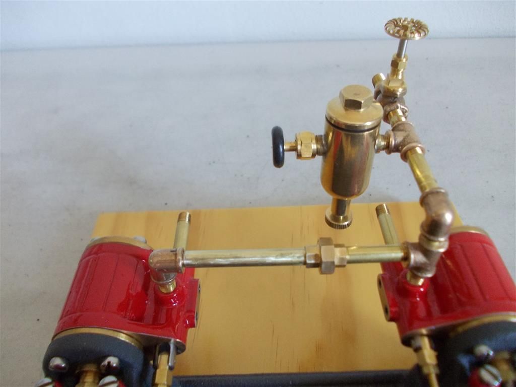
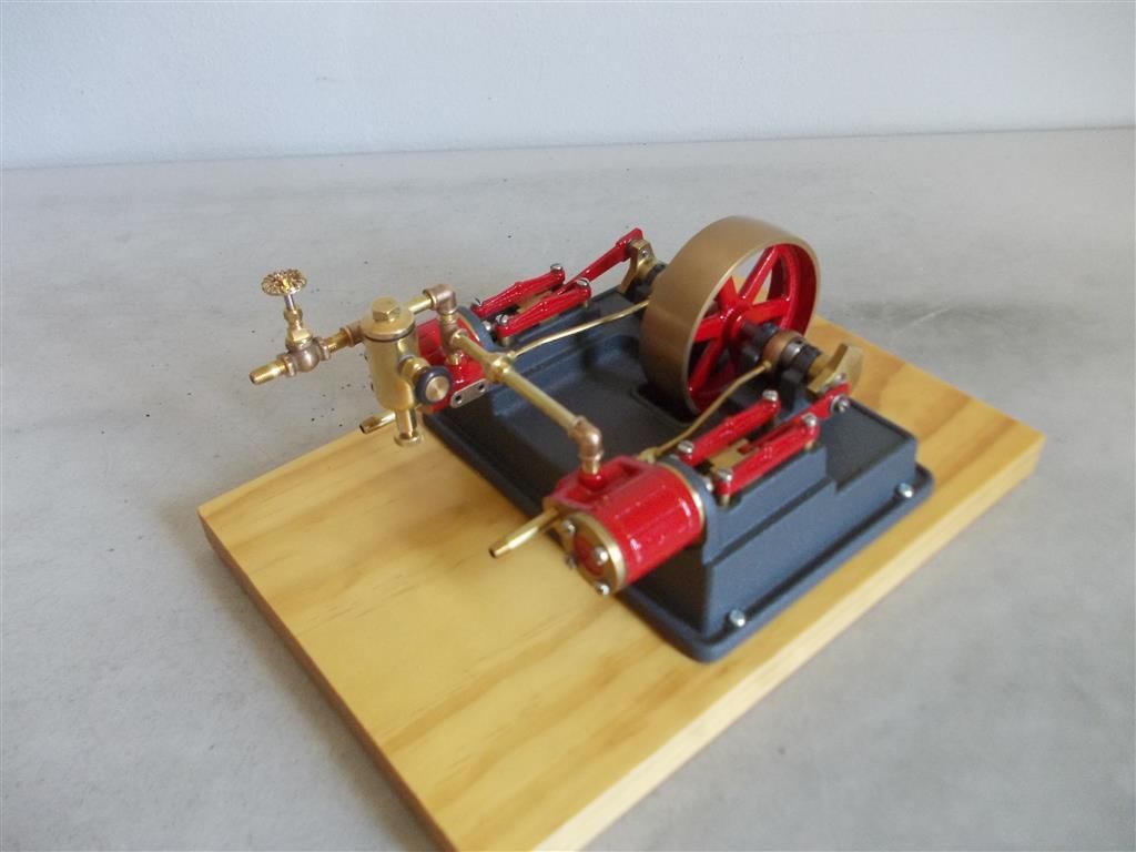
I have almost finished building the PM Research 7BIM twin cylinder engine. I just need to tweak the valve timing a bit then add the steam tubing which joins the two cylinders (the ''manifold'' on the plans).
1. Does this tubing have to be copper as per the plans ? It would be much easier the cut a thread on some brass tubing and join the cylinders that way.
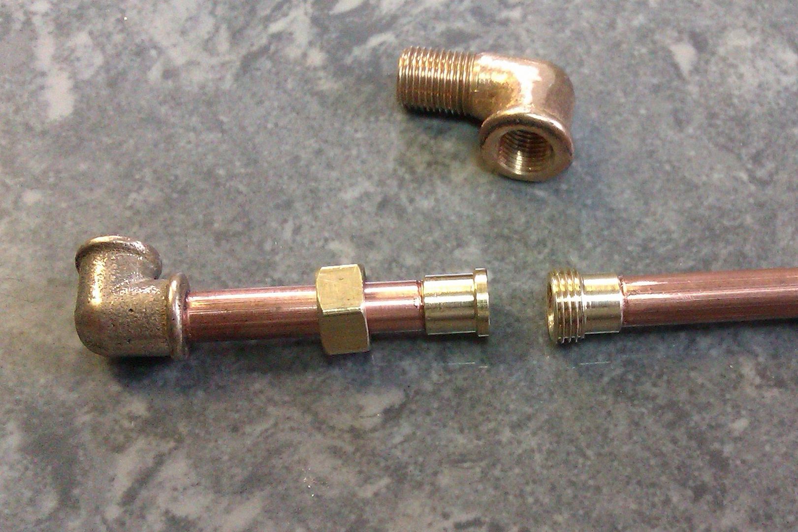
2. I have to use some sort of union to do this. I have never done this before so does anybody have some diagrams or photos to show the process. Which parts will have to be hard soldered as I only have a vague idea how I am going to do this ?
3. Where would I eventually put the displacement lubricator ?
2.Looks like they have a threaded nipple comming out of the valve chest and then a captive nut on a short length of pipe (pipe union) before the tee/elbow. Do you have the tee, union and elbow or are you doing the plumbing from scratch? as this will determine the best approach. If you are doing it as per PMR then no soldering is needed. If doing it the UK model way then you will need different fittings, soldered joints and could use copper pipe as you won't be threading it.
3. I would put the lubricator just before the steam supply splits into two
B. I think I should have bought more of these unions. Does anybody sell them in the UK ?
C. Why use copper at all ? It is much harder to cut a thread on copper than it is on brass although I might have more success now that I have purchased HSS dies.
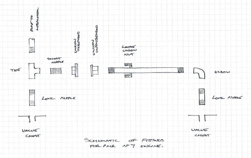
A. It can be done with one union, yours is the correct part, I'll sketch out a schematic of what you need a bit later.
B. Forrest Classics would be the only likely UK supplier, I make my own but as I said above it can be done with one.
C. Copper bends easier than brass so you can avoid having so many elbows or make the pipe follow contours, etc. Most models in the UK use copper with soldered on nipples/ferrules. In the US where your model comes from they tend to just use straight lengths of threaded tube and threaded fittings to suit.
Here you go, if done this way you will be able to screw all the pipes and nipples into their fittings, the union allowing the last one to turn. Should come up bigger if you click it.
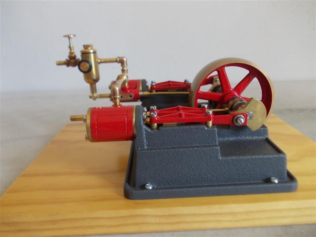
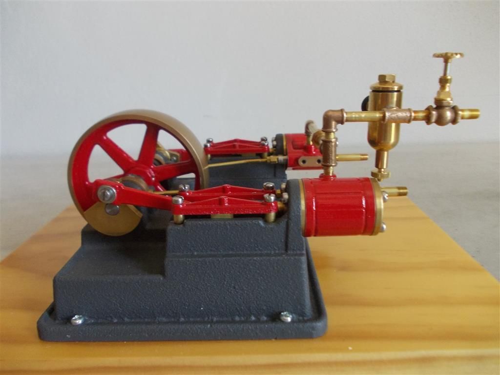
I have been delayed due to a family illness but I have finally had a go at finishing this 7BIM engine by adding the manifold, displacement lubricator and a globe valve. There is still some leaking of air around the tube union on the manifold. I will have another look at this tomorrow. I may have to use some sealant (Loctite 567)
I am also puzzled why there is some air leakage from the bottom of the displacement lubricator ? Note that there is no oil in it now as I am not running it on steam yet.
Looks good Brian, I usually add a drop of liquid gasket to teh pipe fittings which is like a silicon sealant, seals the joint and is easy to take apart when needed.
Is the drain at the bottom of the lubricator threaded or just a loose push type?
2. I am also puzzled about another point : before I installed the manifold connecting the two cylinders I was running the engine in by connecting the air hose to one cylinder at a time. After turning the compressor off the engine would continue to run for about 16 revolutions. But now that I have connected both cylinders the engine will only run for about 5 revolutions.
Does this indicate that I have not got both cylinders synchronised with each other or is there too much leakage around all the new pipe work ?
Your air hose will contain air under pressure, much like a mini storage tank so this is the air that is driving the engine once the compressor is off 2 cylinders mean half the run on time plus a bit of leakage and mabe a bit more friction for teh dropping air pressure to overcome now the two are coupled together. You also have some momentum in teh flywheel, again this will now be split between the two cylinders so half the effect.
Without seeing inside your lubricator the drain may need to be unscrewed to seal the hole, they are often a captive screw so screwing out will close the hole, screwing in lifts the drain off its seat and the steam pressure will drive the condensate out.
The friction will be the same as both sides of the engine (both cylinders) were connected to the axle when I was running air through one cylinder at a time. I will see how it runs when I have put some sealant on all the pipe work. I suspect that I am getting quite a bit of leakage.
I have had another attempt at fitting the manifold : I got it closer to the cylinders (it looks more elegant this way) by using shorter vertical pipes. I also got a much tighter fit on the tube union by experimenting with slightly different lengths of horizontal pipe. I can feel no air leaking from the tube union now and I did not have to use any sealant.
It still only runs on for about 6 revolutions after turning off the compressor so I guess this is as good as it gets. I will need to build another bigger base with some cabinet handles. I did not think of that when I fitted it to this small base. It is a pity that the only timber I can buy in Cairns is pine ; a nice piece of cedar or mahogany would look better,
Sorry, I should not have deleted the earlier photos.
1. Where can I buy some copper cups to catch the water from the exhaust ? I have seen them on youtube videos but I have no idea where to buy them.
2. Could I use (yellow) gas plumbers tape as a sealant ? It is rated for 100-250 degrees Celsius and would be a cheaper option .
I have been running the engine with some oil in the displacement lubricator and I now have some oil leakage around my pipe fittings (about one drop per hour). This indicates two things :
1. Even when running on air some oil is picked up and transmitted thorough the pipes. There is also oil slowly dripping from the exhaust pipe so the oil must be getting all the way to the cylinders/pistons.
2. I still have some air leakage around my pipes. The leakage is not just from the tube union but also the L and T fittings.
How can I best solve the air leakage ? I am first going to try some yellow plumbers tape. I also have Loctite 567 thread sealant. Are there any other possible solutions that I have not thought of ?
Either of those will work fine or as I said a liquid gasket ( car shop) or some form of silicon sealant ( DIY store). There are also the more traditional oil based pipe sealants such as Boss White, Hawk White, Stag, etc. Not sure whats available down under but you should be able to get something from a plumbers merchant. In full size these fittings would often have tapered threads which are more self sealing than teh parallel ones on the models though a bit of hemp and boss white was often still used.
You said you live in a humid part of Oz, do you have a moisture trap on the compressor? if not what may be happening is the moisture in the air condenses out in the air hose and pipework and some of this may be finding its way into the lubricator and displacing the oil.
Brian, you were wondering why that when you ran the motor with both cylinders coupled it only ran on 6 revs, I think the reason is that you have twice the friction, and moving mass, but you only have the one flywheel that you had when running single cylinder.
No, even when I was running it on one cylinder at a time, both sets of pistons and valves were connected to the axle and flywheel with their eccentrics and cranks so the amount of friction is still the same.
I think I am losing much more air than I first thought. Tomorrow I will try sealing all the pipe work with either plumbers tape or Loctite 567.
Well all the pipes and joins have been sealed with Loctite 567 and I used plumbing tape on the tube union but it has not made much difference : the engine still only runs on for 5 revolutions after turning off the compressor whereas before it would run on for over 15 revolutions. I guess it is what it is ! But I am surprised that adding the manifold, lubricator and globe valve has resulted in such a loss of pressure in the system. Now I can see why many people prefer to solder the pipe work.
Note that a similar thing has happened with the single cylinder 3BIM engine : before all the piping was added it would run for over 20 revolutions after turning off the compressor but now it only runs on for 7 revolutions.