building the triple expansion engine in M.E.

Advert

building the triple expansion engine in M.E.

Home Forums Model Engineer. building the triple expansion engine in M.E.

Viewing 21 posts - 1 through 21 (of 21 total)
  • Author
    Posts
  • #37535
    wheeltapper
    Participant
      @wheeltapper

      query on making the crankshaft

      Advert
      #91896
      wheeltapper
      Participant
        @wheeltapper

        Hi guys.

        I am confused again ( no surprise there then)

        I fancied having a go at this engine and I thought the crankshaft looks the most complicated bit so if I can do that the rest should be reasonably easier,

        BUT, I can't get my head round how the ends are marked out.

        Am I to assume that there are 10 centres marked on each end?

        3 for the cranks, 6 for the cams and 1 for the centre.

        I laid it out on a piece of paper and it looks awfully crowded.

        Any help and guidance is appreciated.

        Cheers

        Roy

        #91897
        JasonB
        Moderator
          @jasonb

          Thats it.

          As shown there is only one set of cam centres but you will end up with six equally spaced around a 4mm dia circle.

          Certainly a case for the smallest ctr drill you have!!

          #91899
          wheeltapper
          Participant
            @wheeltapper

            Thanks for that Jason, the other challenge seems to be making sure you use the correct centres so the right cams go with the right crank.

            Could be fun indecision

            I can't figure out which of the two centres for each cam relates to the position of the cam on the shaft.

            get that wrong and you have two cylinders going forward and one going in reverse.blush

            Cheers

            Roy

            #91900
            JasonB
            Moderator
              @jasonb

              It wants drawing out a few times larger than actual size. And then make a note of which way will be forwards then say make all the cams that are forward of the crank the nearest the web and all those reverse the furthest from the web.

              As all the valve chests are on teh same side of the cylinders so long as you use the same relationship for each pair it won't matter which is forward and which reverse.

              If you are not sure I'll sketch it out

              .

              #91901
              wheeltapper
              Participant
                @wheeltapper

                Cheers, that makes sense.

                A sketch would be helpful if it's not too much trouble.

                Roy

                #91903
                JasonB
                Moderator
                  @jasonb

                  Off into the shed now but will do it later.

                  J

                  #91907
                  Gunnar M
                  Participant
                    @gunnarm

                    Hi!

                    I make a drwing for you, hope it help.

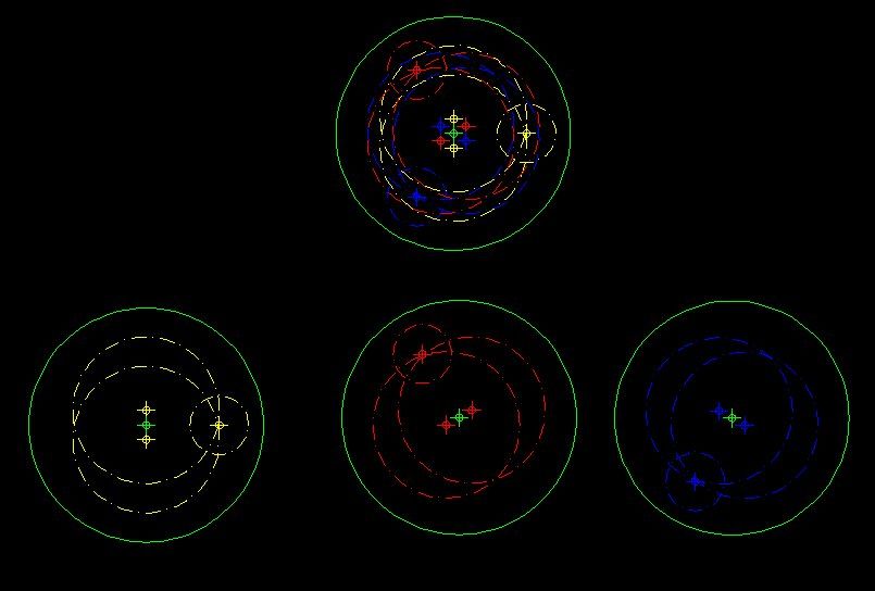
                    Crankshaft markings

                    Regards

                    Gunnar

                    #91914
                    wheeltapper
                    Participant
                      @wheeltapper

                      Thanks, it's all becoming clearer now.

                      Roy

                      #91915
                      Sub Mandrel
                      Participant
                        @submandrel

                        I don't think Morgens made it very clear how /why the eccentrics are set out the way they are.

                        Neil

                        #91916
                        David Clark 13
                        Participant
                          @davidclark13

                          Hi There

                          Three crankpins as shown on the drawing.

                          So, at 120 degrees apart.

                          Eccentrics at 90 degrees to the crankpin, one each side.

                          Simples.

                          regards David

                          #91920
                          JasonB
                          Moderator
                            @jasonb

                            Well Gunnars sketch shows how each pair relates to the crank but there is still a chance of getting the forward & reverse eccentrics transposed. Hopefully this will show you how each of the six eccentric centres relates to the position along the crank.  As I have drawn it my reversing lever will be the opposite way round to Morgens but as I said so long as all three pairs of eccentrics are consistant it makes no difference as there is no lead or lag to the eccentrics. Click to enlarge.

                            Triple eccentric layout

                            Note the drawing of the right hand pair of eccentrics in the mag is wrong, I susspected it earlier but now I have drawn it out it is definately wrong. The amount of throw shown should be the same for middle and R/H not larger on the R/H crank.

                            J


                            Edited By JasonB on 01/06/2012 20:54:30

                            #91921
                            wheeltapper
                            Participant
                              @wheeltapper

                              Thanks for that Jason, by jove I think I've got it.

                              cheers

                              Royyes

                              #91923
                              JasonB
                              Moderator
                                @jasonb

                                I've altered it to be timed like Morgens, will stick up the pic in the morning.

                                #91943
                                JasonB
                                Moderator
                                  @jasonb

                                  Reveised drawing below for those that want it timed as per Morgens.

                                  Revised Triple Layout

                                  #91949
                                  wheeltapper
                                  Participant
                                    @wheeltapper

                                    Thanks Jason, I'll print that and study it.

                                    cheers

                                    Roy

                                    #91983
                                    Sub Mandrel
                                    Participant
                                      @submandrel

                                      90 degrees might be the easy way to place the eccentrics, but surely not the best?

                                      Neil

                                      #91986
                                      JasonB
                                      Moderator
                                        @jasonb

                                        I did mention about them having no lead but on such a small engine I doubt its worth worrying about.

                                        I'll leave you to do the drawing with say 7.5 degree leadsmile p

                                        J

                                        #92186
                                        julian atkins
                                        Participant
                                          @julianatkins58923

                                          i am not familiar with this design, but surely with stephensons gear with launch type links and nil lead in full gear, the amount of advance on the eccentrics = lap on the valves, measured by axial distance as opposed to in degrees. its then quite a simple matter to work out the angle of advance. if the eccentrics were at 90 degrees to the cranks that would be quite wrong if there was lap on the valves… which i am sure there is! if the design is with cams and poppet valves the same principle applies?

                                          cheers,

                                          julian

                                          Edited By julian atkins on 07/06/2012 12:46:42

                                          #92187
                                          David Clark 13
                                          Participant
                                            @davidclark13

                                            Why are you sure?

                                            Do they have lap on piston valves?

                                            regards David

                                            #92188
                                            julian atkins
                                            Participant
                                              @julianatkins58923

                                              dave,

                                              for any form of expansive working slide valves and piston valves need lap, otherwise the steam continues to enter the cylinder right up to the exhaust/release point

                                              cheers,

                                              julian

                                            Viewing 21 posts - 1 through 21 (of 21 total)
                                            • Please log in to reply to this topic. Registering is free and easy using the links on the menu at the top of this page.

                                            Advert

                                            Latest Replies

                                            Home Forums Model Engineer. Topics

                                            Viewing 25 topics - 1 through 25 (of 25 total)
                                            Viewing 25 topics - 1 through 25 (of 25 total)

                                            View full reply list.

                                            Advert

                                            Newsletter Sign-up