Building the ‘Potty mill engine’ the beginners way.

Advert

Building the ‘Potty mill engine’ the beginners way.

Home Forums Work In Progress and completed items Building the ‘Potty mill engine’ the beginners way.

Viewing 25 posts - 26 through 50 (of 57 total)
  • Author
    Posts
  • #203407
    Gas_mantle.
    Participant
      @gas_mantle

      Hi,

      Other commitments meant I didn't get a lot done today however I did manage to finish the cylinder head and get it fitted.

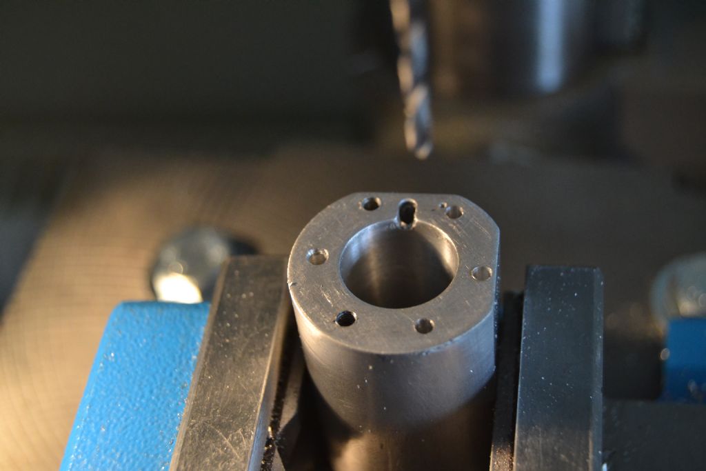
      After a while thinking about it I decided to stick with the 6 hole version that I've already made and hope I have enough room in the cylinder walls to drill and tap. There's only really one hole near the base mounting face that is risky but I think with care it's achievable so here's how it went

      Firstly I gave the cylinder side of the head a tidy up, I'd cut this face off in the lathe by parting it off so it needed a bit of filing and emery paper to clean it up a bit

      potty mill cylinder head 2 (1).jpg

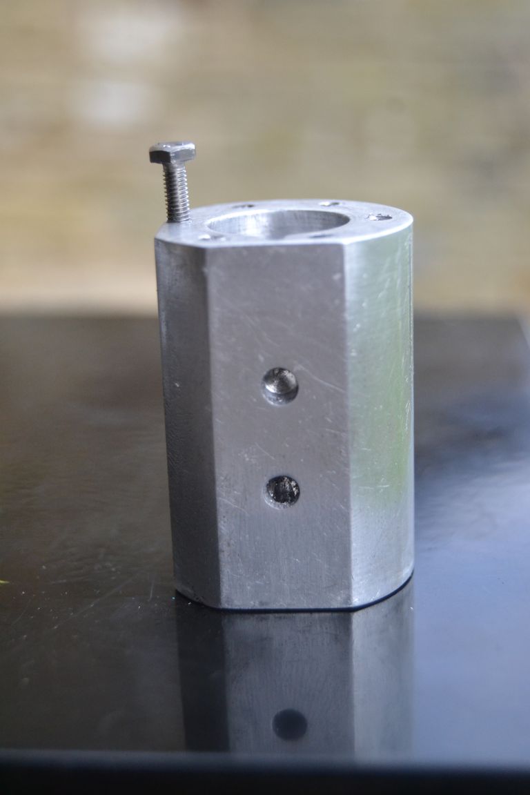
      Next came the bit I wasn't looking forward to – drilling the cylinder block. Since the head mounting holes are slightly out of line I used it as a template for locating my drill, although I forgot to take a photo.

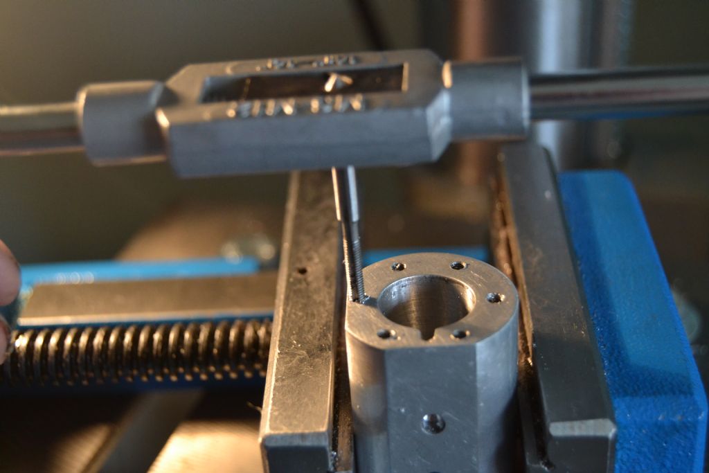
      Anyway you get the idea and can now see that it's only the hole against the base mounting face that is likely to cause problems. I did cheat a bit by putting 2 thin shims under one side of my drill vice to try and coax the drill bit to cut very slightly inward.

      potty mill cylinder head 2 (2).jpg

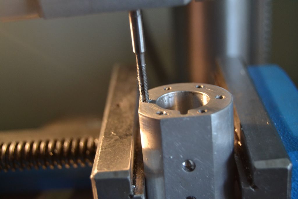
      Similarly with the tap I've tried to gently persuade it inward – so far so good.

      potty mill cylinder head 2 (4).jpg

      potty mill cylinder head 2 (5).jpg

      Maybe not precision engineering at it's finest but I did get away with it – just.

      potty mill cylinder head 2 (7).jpg

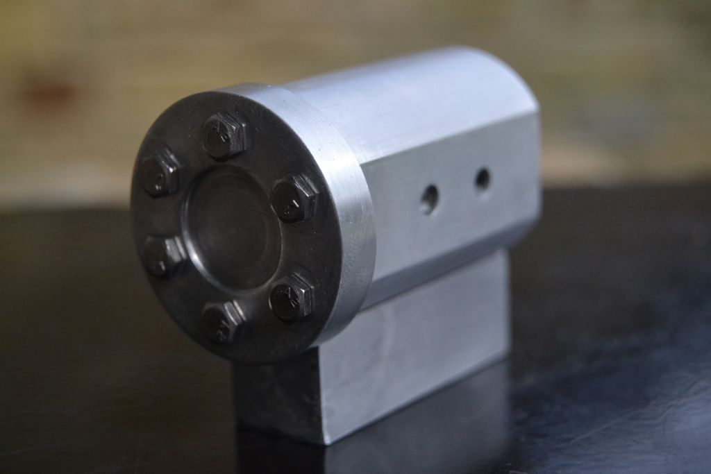
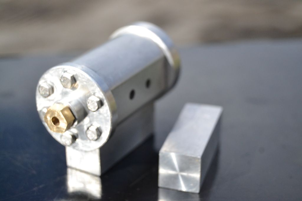
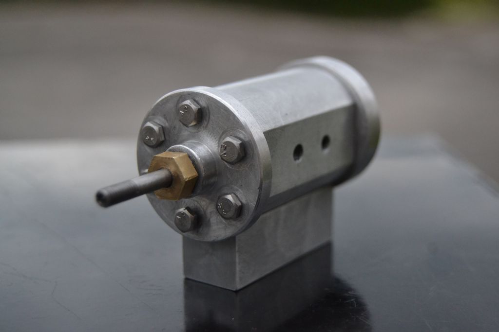
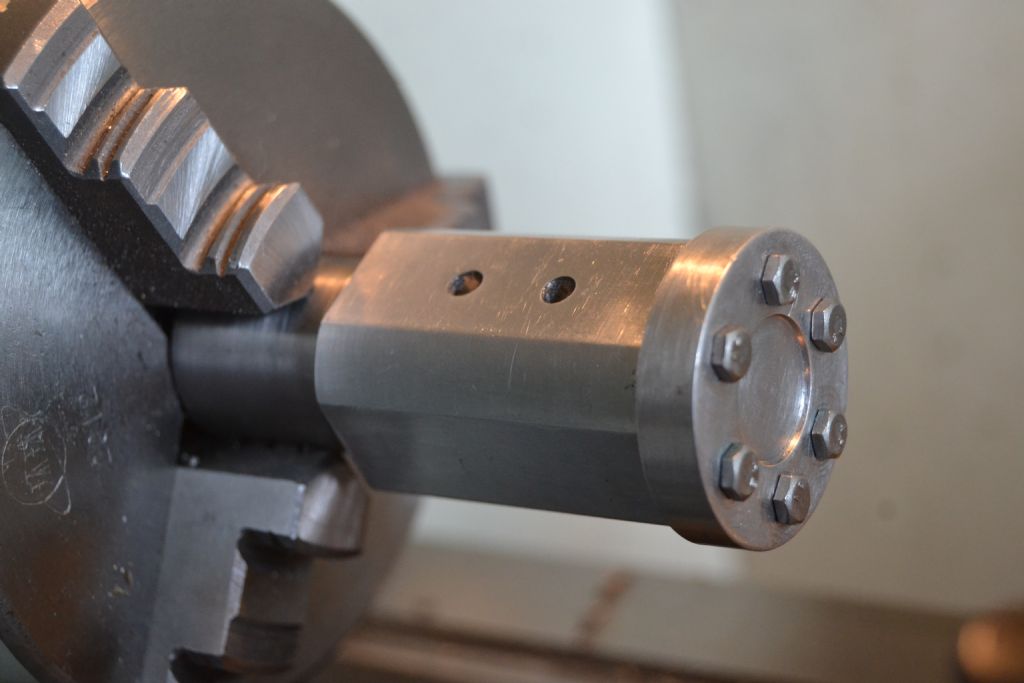
      All holes tapped and head bolted on.

      potty mill cylinder head 2 (10).jpg

      potty mill cylinder head 2 (11).jpg

      With hindsight I think I was pushing my luck a bit trying to get 6 bolts in rather than 4, if I was to make another of these engines I'd be inclined to stick to 4 holes next time.

      Having said that, it did turn out ok and although one of the holes is a tad out of line I'm pleased with the result.

      In doing the head this way I've now committed myself to doing the other end of the cylinder the same way but next time might make the radius of the bolt ring a tiny bit smaller without it being visually noticeable.

      Peter.

      Advert
      #204043
      Gas_mantle.
      Participant
        @gas_mantle

        Hi,

        Having spent a few days helping a neighbour building flat pack furniture, I've at last had some time to progress with the engine.

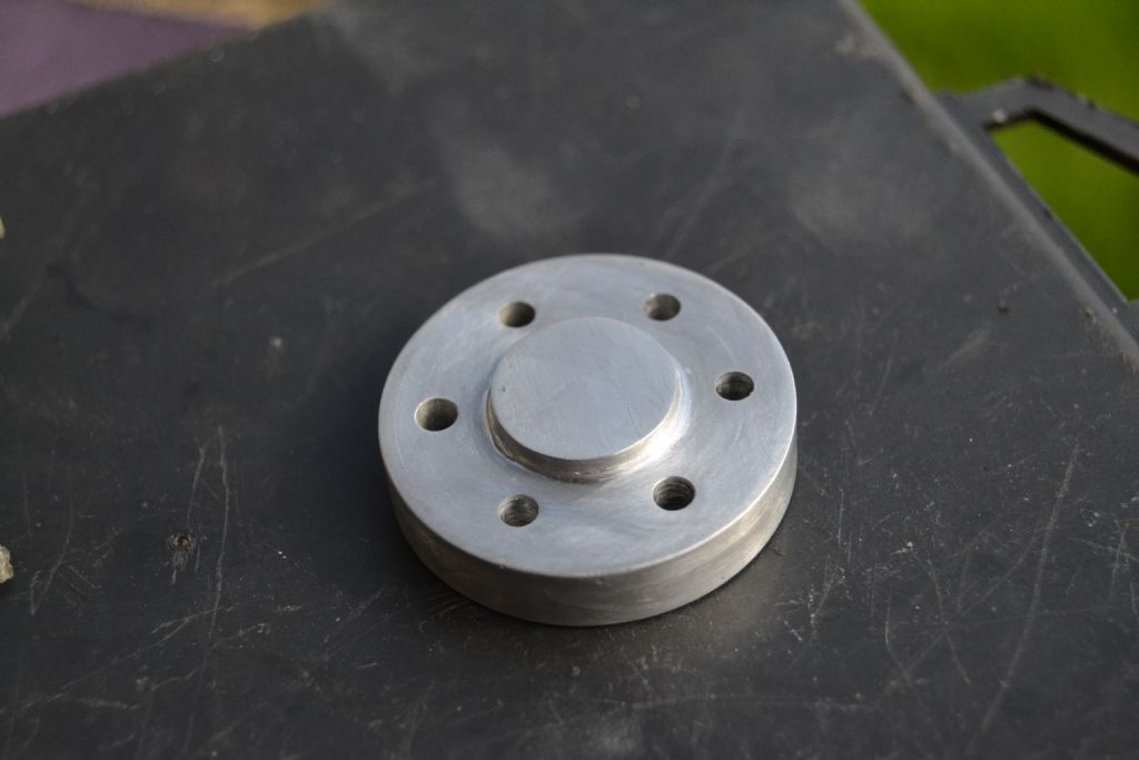
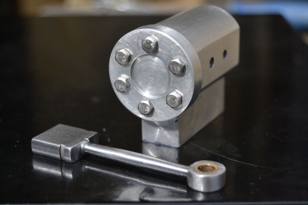
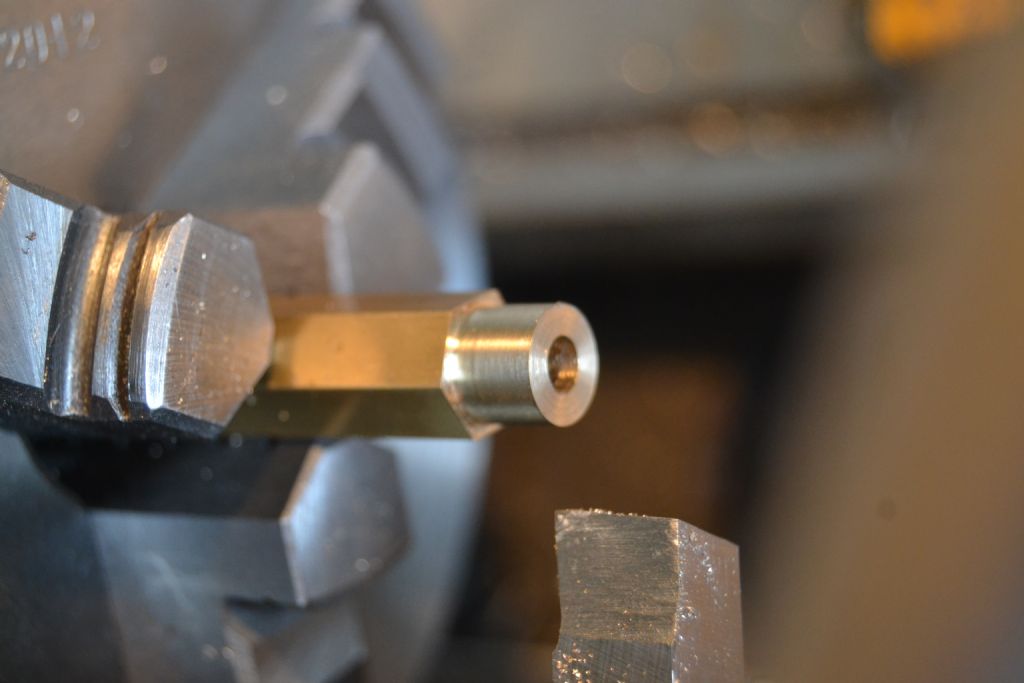
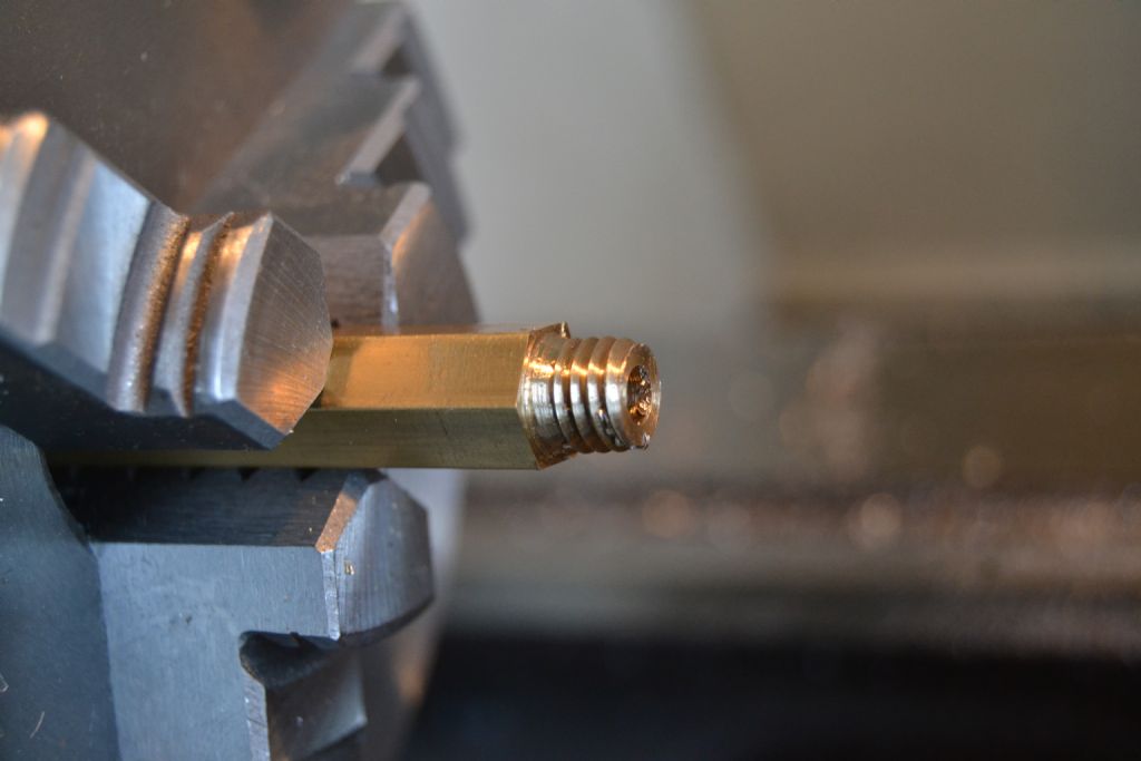
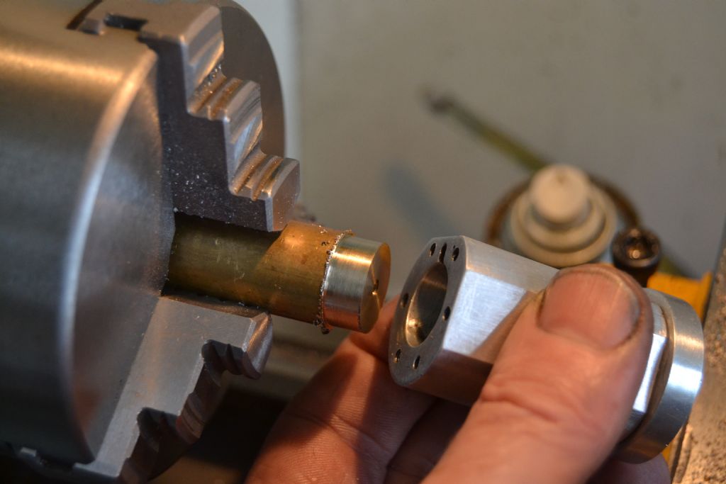
        Having made one cylinder cover I decided the next obvious step was to make the piston rod end cover. This part is very similar to the cylinder head cover but with the addition of the piston rod hole and its brass guide.

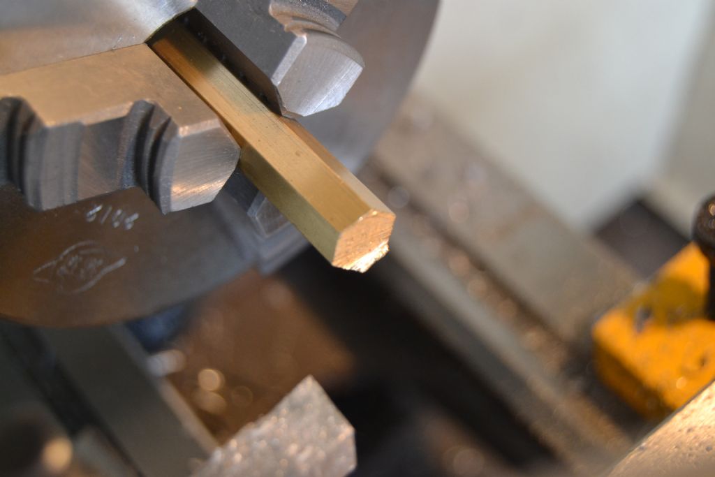
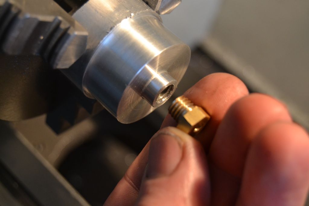
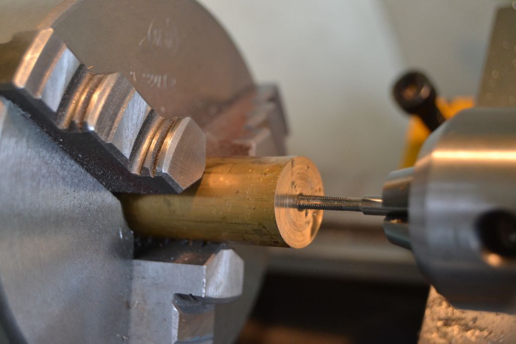
        I made the brass support guide from a 10mm hex brass bar drilled out to 4mm and threaded on one side to an M8 thread.

        potty mill piston rod guide (1).jpg

        potty mill piston rod guide (2).jpg

        potty mill piston rod guide (3).jpg

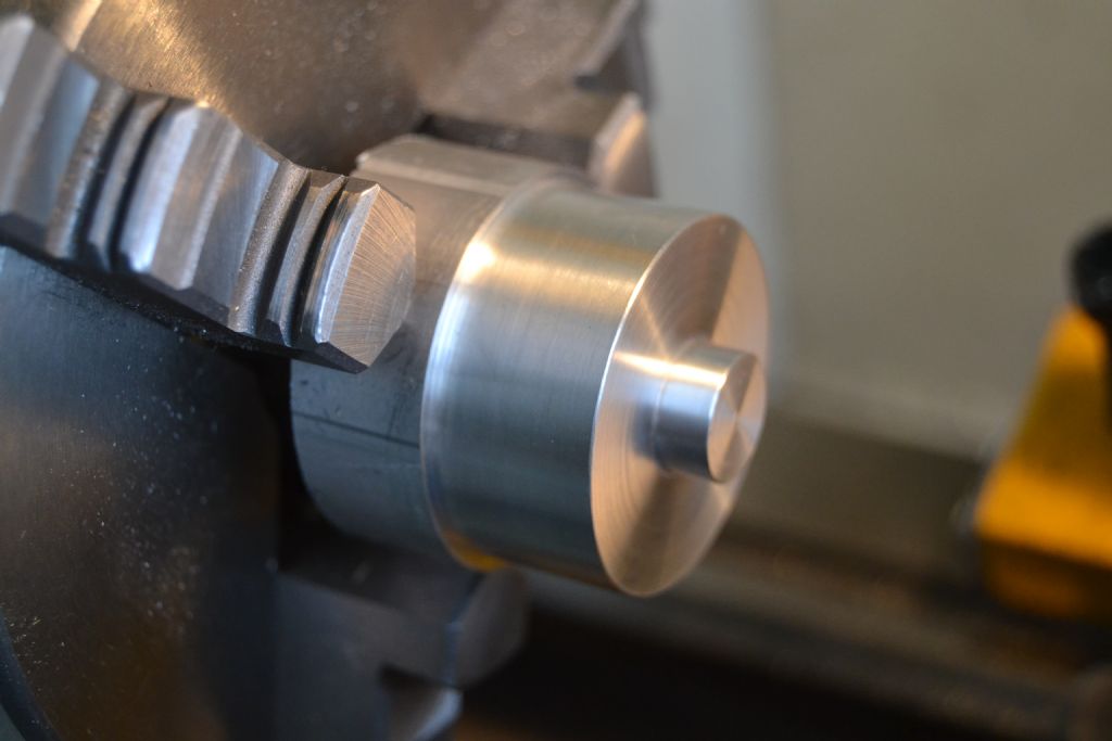
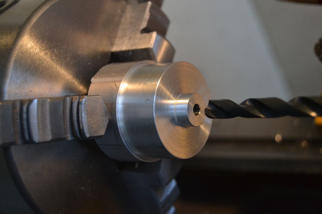
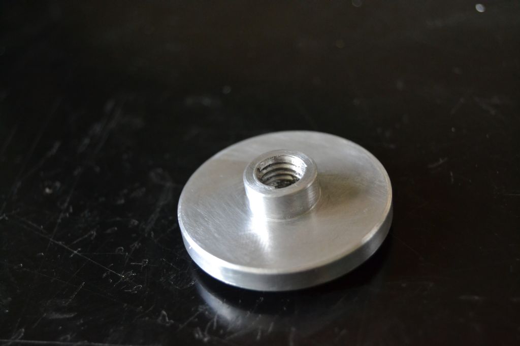
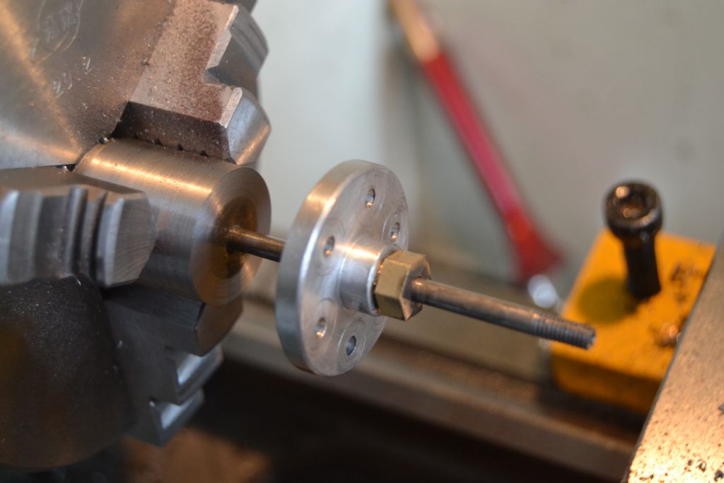
        Having then parted off the guide I began on the cylinder end cover, firstly by turning to diameter and facing the end then drilling out the central bore for the piston rod.

        potty mill cylinder cover piston rod end (2).jpg

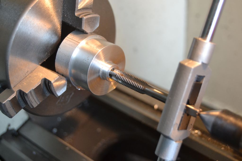
        Part of the central bore needs opening out to allow a thread to be cut to accept the brass guide.

        potty mill cylinder cover piston rod end (4).jpg

        potty mill cylinder cover piston rod end (6).jpg

        potty mill cylinder cover piston rod end (7).jpg

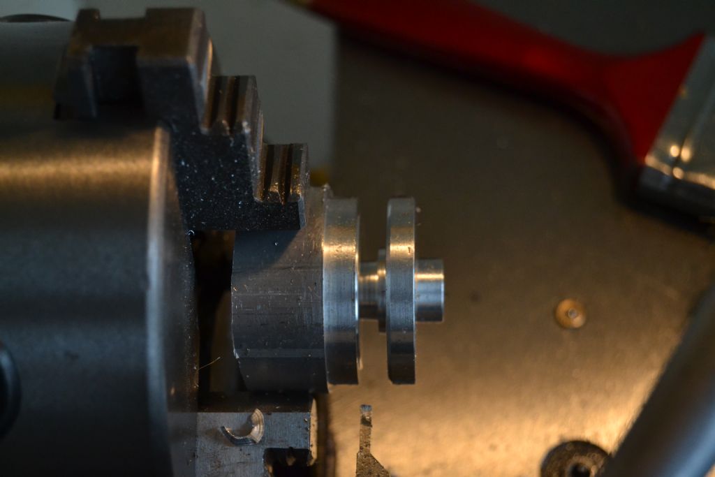
        Next job part off leaving a short raised spigot to fit align in the cylinder.

        potty mill cylinder cover piston rod end (10).jpg

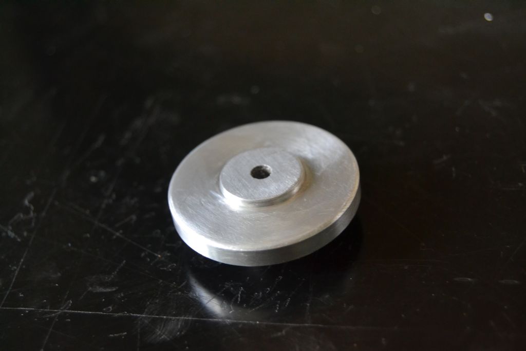
        My parting tool doesn't have enough reach so the last bit was hacksawed then filed by hand – leaving this.

        potty mill cylinder cover piston rod end (11).jpg

        potty mill cylinder cover piston rod end (12).jpg

        Not a very good photo but you get the idea how it looks once drilled and fitted. Still needs a bit of polishing up but the fit is good and I'm hoping all is going to plan

        potty mill cylinder cover piston rod end (14).jpg

        Peter.

        #204071
        Black Cat2
        Participant
          @blackcat256889

          This is brilliant stuff Peter, One thing please-how did you do the fishbelly taper con rod?
          Jonathon

          #204089
          Gas_mantle.
          Participant
            @gas_mantle

            Hi Jonathon,

            I ended up hand filing the rod while it was still in the lathe then finished it with emery paper, there's still a very small amount to come off one end but I'll do that by hand when the engine is nearly complete. If you scroll back to page 1 there are photos.

            On the plan it is shown as an 8* taper, I tried all different methods of aligning the topslide on my machine to do that but couldn't manage without something catching. I'm sure it will be possible to do it on my 8×16 machine but it was taking me so long I decided it would be easier to file over such a short taper.

            Peter.

            #204103
            Mark Williams 21
            Participant
              @markwilliams21

              Hi Peter,

              I'm finding your thread extremely interesting as I'm just about to start in the hobby, pillar drill bought, X1 mill getting delivered wednesday and depending on my luck with Fleabay Myford lathe could be mine very soon. so I'm looking for my first project and like the look of this one, are the plans readily available and if so where from? thanks and keep up the good work.

              Mark.

              #204107
              Gas_mantle.
              Participant
                @gas_mantle

                Hi Mark,

                Glad you find the thread interesting, I'm very much a beginner myself I thought it would be useful to create a beginners build thread, it's useful to have the 'experts' comment with tips / better ways of doing things etc so we all learn a bit.

                I'll have a word with the guy who gave me the plans and see if he'll forward you a set.

                Peter.

                #204110
                Neil Wyatt
                Moderator
                  @neilwyatt

                  Mark,

                  If you want a good deal on a Myford the prices asked in the Model Engineer/MEW classifieds are often more reasonable than Ebay.

                  Neil

                  #204154
                  Gas_mantle.
                  Participant
                    @gas_mantle

                    Hi,

                    With a lot of distraction today I didn't get as much done as I expected, I had intended to try and complete the piston rod and the piston itself. I only managed to get the rod done but it's now complete and as I took photos I thought I may as well post them.

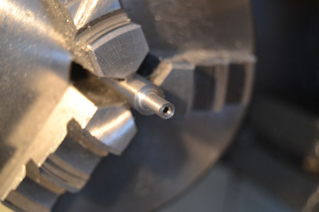
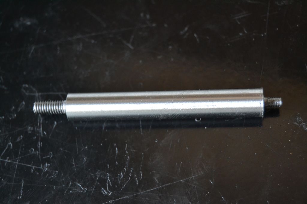
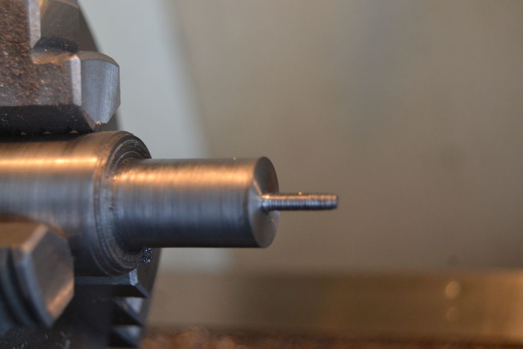
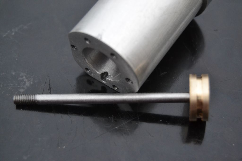
                    The rod is simply a silver steel rod with an M3 thread for the piston at one end and an M4 thread for the crosshead at the other. I had hoped to try and make the piston and use it as an arbor to support and drive the rod held against a tailstock centre. I thought this would allow me to kind of machine the piston and rod as one item ensuring good a good concentric fit. However because of the way the piston is threaded at one side only I decided it was going to be easier and (hopefully just as good) to make a temporary steel arbour to turn the rod.

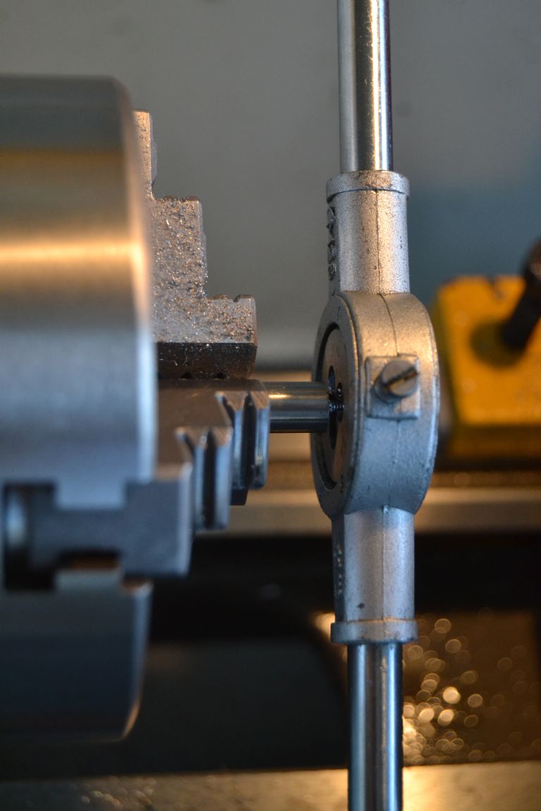
                    First I cut an M3 thread in one end of the silver steel.

                    potty mill piston rod (1).jpg


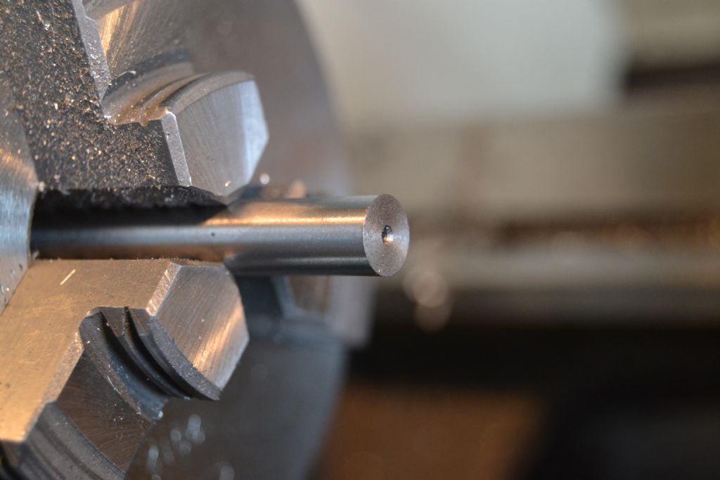
                    Next job, make a small hole in the other end for the tailstock centre and turn to size for an M4 thread – this will be the crosshead end.

                    potty mill piston rod (3).jpg

                    potty mill piston rod (5).jpg

                    potty mill piston rod (6).jpg

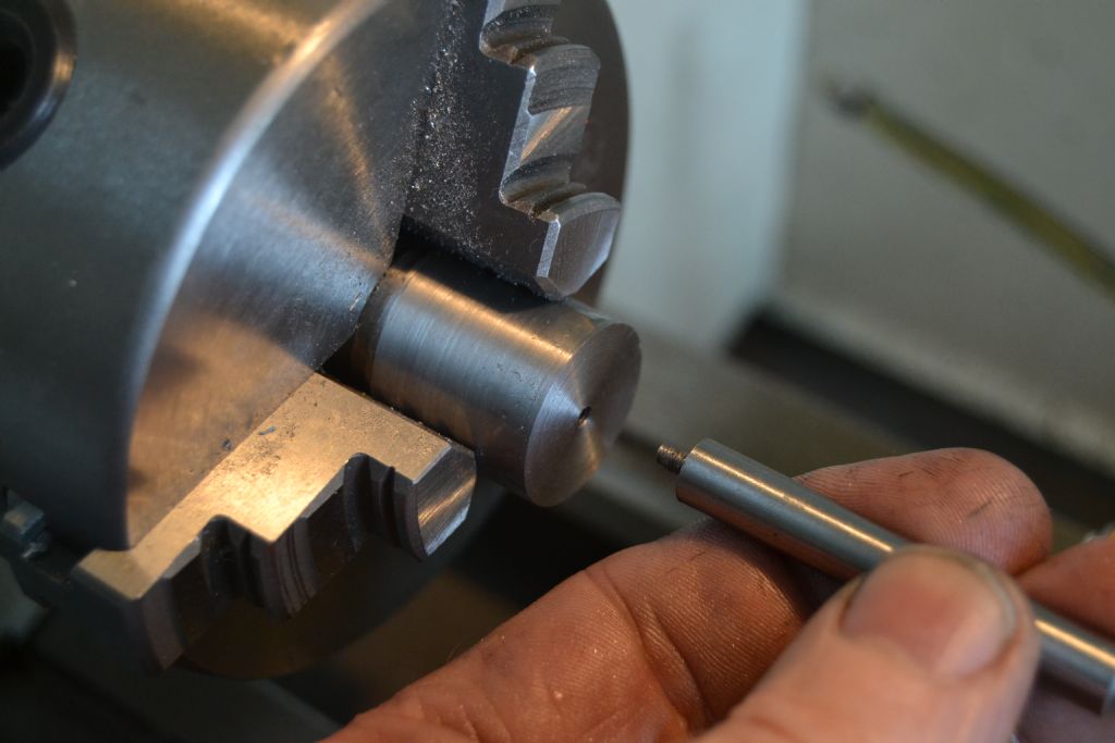
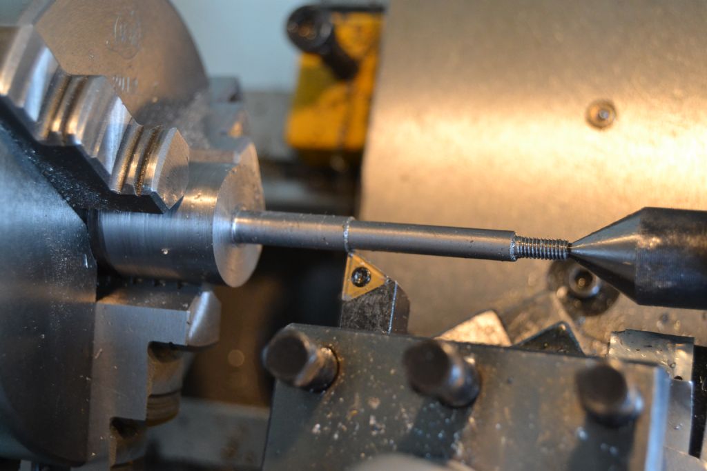
                    I then made a temporary M3 threaded arbour to both support and drive the rod for turning – this was the procedure I had considered using the piston for but decided against.

                    potty mill piston rod (7).jpg

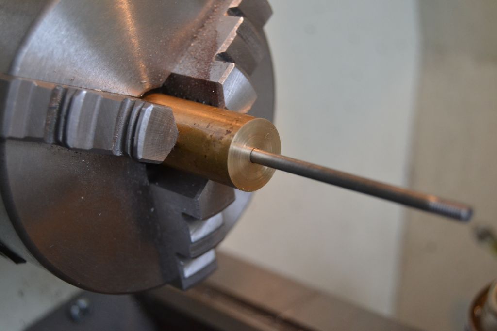
                    It's the first time I've ever cut silver steel and found it a bit tougher than other materials I'm used to. I was hoping that by turning it down to a diameter of 4mm over a 60mm length that it wouldn't flex or try to climb over the tool bit. I found it worked well using a carbide bit, the finish wasn't great but I just wanted to get close to the required 4 mm dia then use a better tool tool and finish of with fine emery paper.

                    potty mill piston rod (8).jpg

                    Once close to the diameter I started just using emery and a drop of oil till I got a good fit with the cylinder end cover and guide.

                    potty mill piston rod (9).jpg

                    Finally arriving at this.

                    potty mill piston rod (10).jpg

                    Not the most complex of parts but it turned out ok and it's slowly beginning to look like the start of an engine.

                    With a bit of luck I'll get the piston done tomorrow.

                    Peter.

                    Edited By Peter Nichols on 13/09/2015 17:04:40

                    #204261
                    Gas_mantle.
                    Participant
                      @gas_mantle

                      Hi,

                      Well since I didn't get the piston made yesterday I thought I'd have a bash at it this morning.

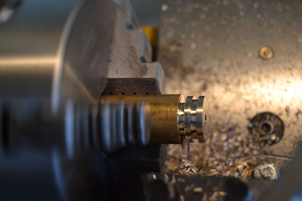
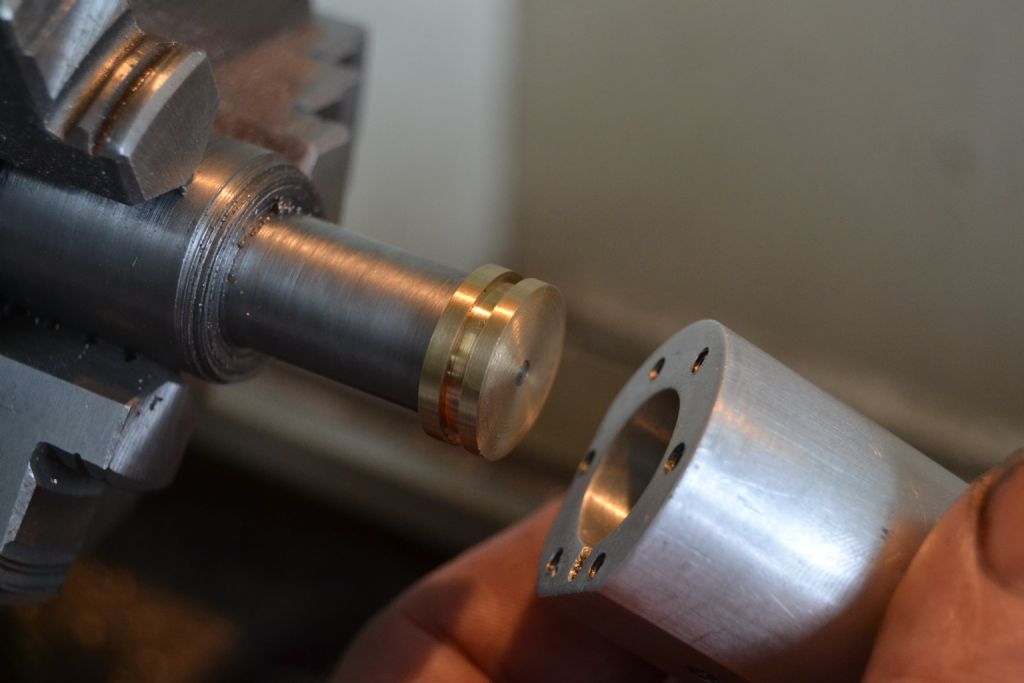
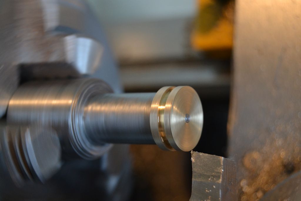
                      Basically it involves making a brass disc 16mm in dia and 5mm deep with a groove to accept graphite packing, it is threaded from one side only to take the M3 thread on the rod I've already made.

                      As I mentioned earlier I had hoped to try and machine the piston and the rod together as though they were one item, but I decided that wasn't practical (and probably wasn't necessary either !) so I came up with this rather convoluted way of making it, here's how it went :-

                      First job was to face off a piece of brass then drill and tap the M3 thread.

                      potty mill piston (2).jpg

                      Then drill a larger hole part way through to accept the plain shank of the piston rod so the threaded portion of the hole is only at one end.

                      potty mill piston (3).jpg

                      I turned the diameter as close as I could to size but deliberately left it slightly over size. Since the piston is only threaded at one side it is not symmetrical but has a top and a bottom, I wanted to take the final cuts to it's diameter from the other end (nearest the chuck) as this will be the way it finally operates in the cylinder and will hopefully allow me to get a better close fit allowing for any inaccuracy in the cylinder bore.

                      potty mill piston (4).jpg

                      Next I cut the packing groove and parted off.

                      potty mill piston (5).jpg

                      I made a mandrel with an M3 thread – the finish is terrible I know but the tool was getting blunt and for the sake of a temporary mandrel I carried on using it for the last few cuts – the face is an adequate finish for what I need.

                      potty mill piston (6).jpg

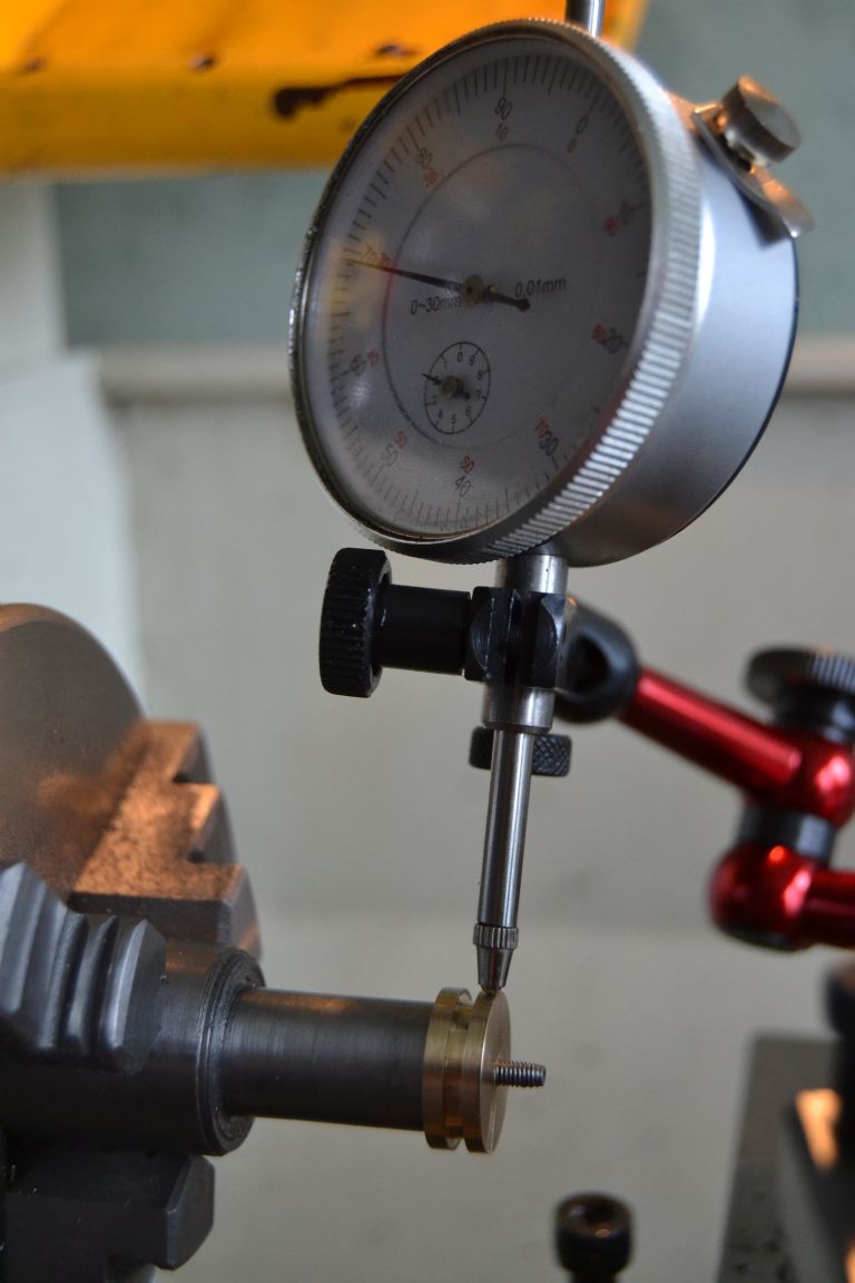
                      Couldn't believe my luck – when turned around it's only 0.02mm out and skimming the diameter to size should lose that.

                      potty mill piston (8).jpg

                      It seemed to take forever taking very small cuts but at least this way I'm trying the fit from the right direction and the mandrel allows me to check the fit over most of it's travel.

                      potty mill piston (9).jpg

                      Once satisfied I gave it a few small facing cuts to tidy up the end.

                      potty mill piston (10).jpg

                      potty mill piston (11).jpg

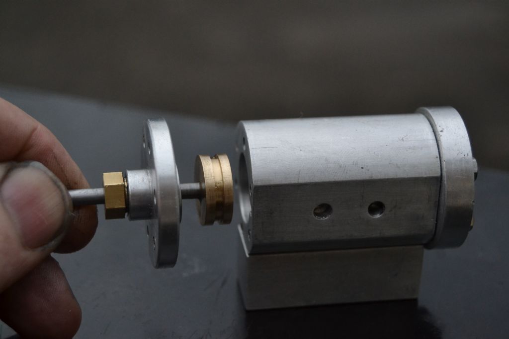
                      I'm sure there must have been an easier way but I got there in the end. The fit is good including when the cover is securely bolted on and if I cover the steam ports with my hand it does make a reassuring pop when pulled from the cylinder

                      potty mill piston (12).jpg

                      potty mill piston (16).jpg

                      Peter.

                      Edited By Peter Nichols on 14/09/2015 15:51:21

                      #204262
                      JasonB
                      Moderator
                        @jasonb

                        Looks good Peter. Usual way is to hold it by the piston rod to do the final skim rather than a mandrel, that way you can be sure it is sitting true to the piston rod thread.

                        #204263
                        Gas_mantle.
                        Participant
                          @gas_mantle

                          Thanks Jason,

                          I did consider doing that but was worried I'd put too much strain on a 4mm diameter rod, but I take your advice next time.

                          Peter.

                          #204282
                          Alex Collins
                          Participant
                            @alexcollins55045

                            Hi Peter and others.

                            This really is a great engine to make as a first project.
                            Here is a video of my attempt.
                            **LINK**

                            Alex.

                            #204301
                            Gas_mantle.
                            Participant
                              @gas_mantle

                              Hi Alex,

                              Thanks for the link, it's impressive that it runs so well as it's your first engine

                              I'm interested in the flywheel you made, I made a much smaller one very similar for my first engine and thought of doing the same for this one. Is it a 100mm steel wheel ?

                              Thanks

                              Peter.

                              #204306
                              Alex Collins
                              Participant
                                @alexcollins55045

                                Hi Peter.

                                The Flywheel was a slab of 4" dia Mild steel that came out of a scrap bin.
                                I cleaned it up and faced it off.

                                The middle I hollowed out with a profile tool – that took quite while.
                                It was cleaned up with L and R handed cutting tools mounted in line with the spindle.
                                Once the centre was drilled I mounted it on an 8mm mandrel for a final skim and to skim the outside edge.
                                Note – The crankshaft is also 8mm. You may want to drill the flywheel 6mm or 7mm and turn the end of crankshaft to suite.

                                My flywheel is mounted with Thread lock.

                                The holes were made with a 16mm End Mill after opening them up to 13mm – the biggest drill I had. The Holes were marked out with a protractor and dividers on a template.
                                I then used a drill and peg to spot the next hole. It almost worked perfic !

                                Alex.

                                #204308
                                Gas_mantle.
                                Participant
                                  @gas_mantle

                                  Hi,

                                  When I started making this engine I bought a 4" mild steel round 1" thick to use as a flywheel so it's good to know your engine works fine using the same.

                                  I've made a few smaller ones of the same design before but the others have had radial holes smaller than my biggest drill bit of 13mm and as I don't have access to a mill I've considered trying a boring bar with the wheel offset. I'm not really sure how my 8×16 machine will cope with a relatively heavy workpiece offset that much but I'm hoping if I counterbalance it right and take it steady it will be ok.

                                  Peter.

                                  Edited By Peter Nichols on 14/09/2015 21:51:18

                                  Edited By Peter Nichols on 14/09/2015 21:53:49

                                  #205290
                                  John Durrant
                                  Participant
                                    @johndurrant47282

                                    For anyone else thinking of making this engine there is a good set of drawings at h-potty-mill-engine-09-02-08.pdf .

                                    I used a program called 'pdf-to-jpg-4-0' to convert it for printing.

                                    #205330
                                    Neil Wyatt
                                    Moderator
                                      @neilwyatt

                                      Not sure that's good form to post a rip off of one of the Magazine's designs on it's own website?

                                      MyTimeMedia might prefer folks bought the back issues of ME, seeing as they paid Stew for the right to publish it…

                                      Neil

                                      #205331
                                      JasonB
                                      Moderator
                                        @jasonb

                                        It (stews drawing) was on the net at least 6months before ME published it and Stew gave Julius permission to redraw it as he has done with several of his other engines.

                                        Don't you only have the right to publish the ME drawn version anyway?

                                        J

                                        PS I won't post where they are incase its bad formwink 2

                                        Edited By JasonB on 22/09/2015 17:56:36

                                        #205336
                                        Neil Wyatt
                                        Moderator
                                          @neilwyatt

                                          You're right, but I was think more in terms of the etiquette of using the ME forum to promote alternatives to ME than any legalities of copyright.

                                          You don't see the Times saying 'for an alternative take on this story buy a copy of the Daily Mail'

                                          Stew has the right to share his original drawings as he sees fit, but It isn't clear from the linked drawings that they are with his blessing.

                                          Neil

                                          #205432
                                          John Durrant
                                          Participant
                                            @johndurrant47282

                                            Sorry, didn't mean to step on anyones toes.

                                            The drawings for this same version of the engine are available in lots of places on the web, and I'm sure that I saw more than one request for copies on this forum.

                                            #205435
                                            John Durrant
                                            Participant
                                              @johndurrant47282

                                              On a lighter note.

                                              The drawing says that "Preferably all tapped holes to be Metric Fine (MF)" Is this really necessary, as I only have metric course taps and dies and would rather do without the expense of a multitude of new taps and dies.

                                              #205437
                                              Gas_mantle.
                                              Participant
                                                @gas_mantle
                                                Posted by John Durrant on 23/09/2015 11:58:00:

                                                On a lighter note.

                                                The drawing says that "Preferably all tapped holes to be Metric Fine (MF)" Is this really necessary, as I only have metric course taps and dies and would rather do without the expense of a multitude of new taps and dies.

                                                Well, I haven't anywhere near finished the engine yet but have used metric coarse so far without any trouble.

                                                My only slight worry now is because I decided to secure the cylinder ends with 6 rather than 4 bolts I haven't got a lot of room left when I come to drill the valve chest securing holes into the cylinder block.

                                                I hope to try an get a bit more done to it today or possibly tomorrow as just lately I've been feeling a tad under the weather and also had other commitments.

                                                Peter.

                                                Edited By Peter Nichols on 23/09/2015 12:23:44

                                                Edited By Peter Nichols on 23/09/2015 12:24:14

                                                Edited By Peter Nichols on 23/09/2015 12:29:38

                                                #205449
                                                JasonB
                                                Moderator
                                                  @jasonb

                                                  For all the nuts and bolts metric coarse will be OK, the only places where fine would be nicer but not essential are things like the piston and valve rod glands

                                                  #205457
                                                  Black Cat2
                                                  Participant
                                                    @blackcat256889

                                                    I was getting worried Peter on case you d given up! You cant di that I ve just got drawings printed..
                                                    I have virtualy no metric taps or dies and will use bsf mostly..
                                                    #205462
                                                    Gas_mantle.
                                                    Participant
                                                      @gas_mantle

                                                      Hi,

                                                      I needed to wait for a reamer and had a few other commitments so I just had a break from it for a while, I'll do the crosshead tomorrow and make a posting when it's done.

                                                      I'm also doing a 'make it up as you go along' wobbler for when I fancy doing something that doesn't involve much thinking

                                                      Peter.

                                                    Viewing 25 posts - 26 through 50 (of 57 total)
                                                    • Please log in to reply to this topic. Registering is free and easy using the links on the menu at the top of this page.

                                                    Advert

                                                    Latest Replies

                                                    Viewing 25 topics - 1 through 25 (of 25 total)
                                                    Viewing 25 topics - 1 through 25 (of 25 total)

                                                    View full reply list.

                                                    Advert

                                                    Newsletter Sign-up