Building the James Coombes (with chips)

Advert

Building the James Coombes (with chips)

Home Forums Work In Progress and completed items Building the James Coombes (with chips)

Viewing 25 posts - 51 through 75 (of 76 total)
  • Author
    Posts
  • #158827
    Steve Withnell
    Participant
      @stevewithnell34426
      Posted by JasonB on 20/07/2014 18:21:13:

      You really need to knock off the edges, a few strokes with a fine file and then a bit of Emery on a block will be enough to break them and allow the paint to form a film rather than flow away from the high spots.

      J

      So just enough to take off the edge without forming an obviously rounded/flat edge?

      Steve

      Advert
      #158841
      JasonB
      Moderator
        @jasonb

        Yep

        #158844
        Steve Withnell
        Participant
          @stevewithnell34426

          Thanks!

          #195176
          Steve Withnell
          Participant
            @stevewithnell34426

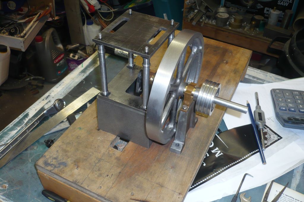
            I got fed up tripping over that unfinished James Coombes, so took another swing at it –

            p1030285.jpg

            I've left the crankshaft over length whilst I get the eccentric and governor drive pulley fitted.

            p1030287.jpg

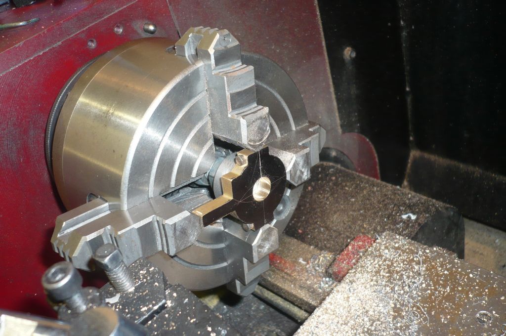
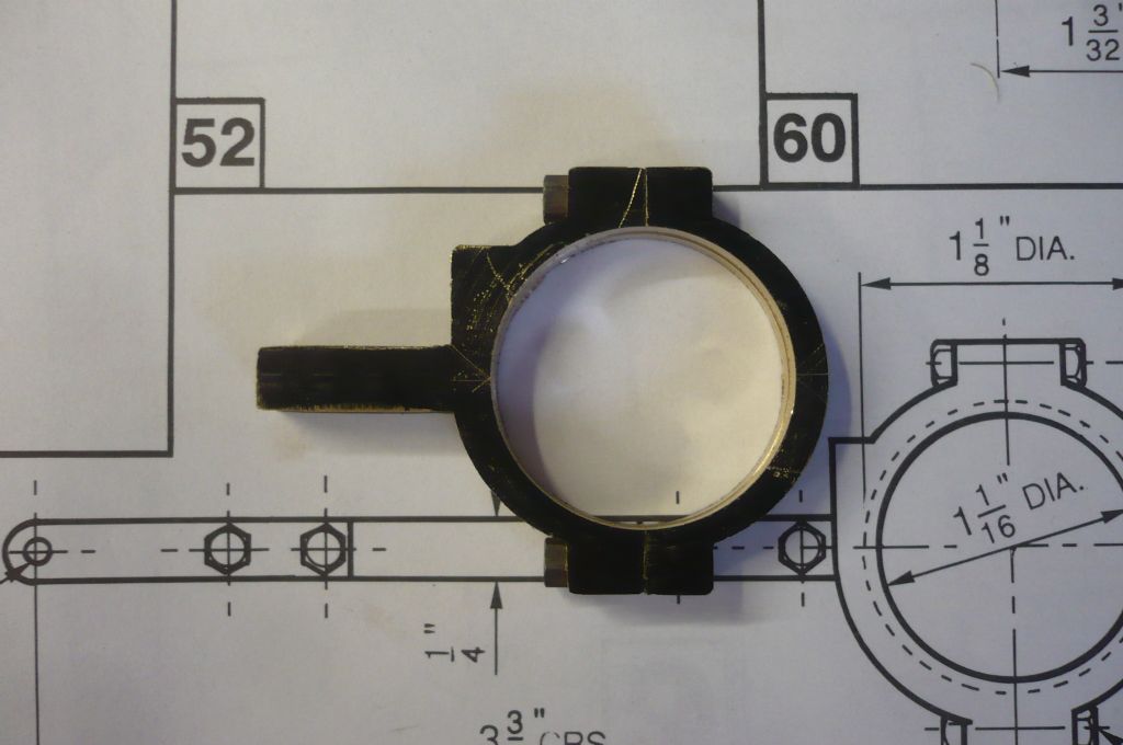
            Making the strap – same method as I used for the Victoria. When I made the straps for the Victoria, I split the extrusion with a thin slitting saw- this approach makes a nice tidy job, but leaves far more material in the strap than is required. It means that the outer of the strap looks quite 'egg shaped' and not concentric with the sheave.

            For the Coombes I used a hacksaw to split the strap extrusion and the cleaned up the two halves in the lathe, so now the strap will 'look right'. Well almost. The issue is purely one of aesthetics, no issue mechanically.

            I make the initial hole with a slot drill.

            p1030294.jpg

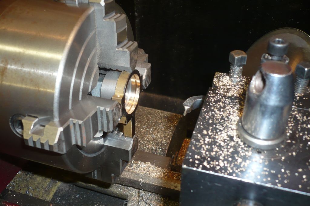
            Here is the tool I use for producing the groove to take the sheave rib – This was made from an old number stamp. I'm not sure how you can do jobs like this without grinding a bit of steel to the right shape.

            p1030292.jpg

            Now I've started, trick is to keep up the momentum!


            Steve


            Edited By Steve Withnell on 27/06/2015 20:46:16

            Edited By Steve Withnell on 27/06/2015 20:49:37

            #195196
            GarryC
            Participant
              @garryc

              Great to see you back working on the engine Steve – I've only glanced at this page for a couple of seconds this morning and already learned from it, I'll go back and read from the start later – I'll be following again for sure…

              Garry

              #195201
              Nick_G
              Participant
                @nick_g

                .

                Nice to see the JC back on the bench. When I was doing mine I had a month or two off around the Christmas period. (decorating and tiling sad) It took me a good few sessions to get back into the swing of it all and remembering what I was up to.

                Nick

                #195211
                Steve Withnell
                Participant
                  @stevewithnell34426

                  https://www.dropbox.com/s/o4466cl48ct2dws/P1000196.JPG?dl=0

                  This should take you to a photo of the eccentric strap I made for the Victoria – you can see how much more material is in this strap, than the one I just finished for the JC. They are both machined from the same extrusion, so the designer must have assumed a lot of metal would be lost in the hacksawing process…

                  Here a link to my library of photo's for the Victoria I built:

                  https://www.dropbox.com/sh/dvrpnbirsgppr3h/AAAGfAnbQK1d6i7PT17AWUr1a?dl=0

                  And here is a link to my James Coombes photo library:

                  https://www.dropbox.com/sh/zue22yuxsike8wf/AADVxsMj4TptMLSRTp6wZmQVa?dl=0

                  You should not need either a password or need to subscribe to get access to the libraries –

                  Steve

                  #195243
                  GarryC
                  Participant
                    @garryc

                    Thanks Steve, I'll be taking a look later…

                    Garry

                    #195961
                    Steve Withnell
                    Participant
                      @stevewithnell34426

                      I'm moving ahead with the JC quite nicely – but have a concern I'd like views on.

                      Stuart provide 3/8" studs to fasten the cylinder to the table. The table is 3/16" thick and the nuts are 3/32" thick. This leaves only 3/32" of stud thread in the cast iron cylinder. The studs are 7BA. Whilst I'm not going to tighten the nuts down with a 6ft length of scaffolding pole – is 3/32" of thread engagement enough? I used a 2mm tapping drill which is slightly tighter than recommended by Stuart.

                      Steve

                      #195975
                      Clive Hartland
                      Participant
                        @clivehartland94829

                        Perhaps counter bore the underside to get a bit more thread, you need 1 1/2 thread diameter depth for a good hold.

                        Clive

                        #195979
                        Steve Withnell
                        Participant
                          @stevewithnell34426

                          Thanks Clive, I have tapped the holes about 4.5mm deep, so I just need to make some longer studs then. Stuart want £15.50 for 25. Ouch.

                          Steve

                          #196023
                          NJH
                          Participant
                            @njh

                            Ouch indeed Steve!

                            You could, of course, make some – or if you are not a purist then some 7BA studding might offer a less expensive route for example see HERE

                            Norman

                            #196093
                            Steve Withnell
                            Participant
                              @stevewithnell34426

                              Thanks Norman. The Stuart "studs" are not strictly studs, just short lengths of threaded rod…So been making 7/16 studs.

                              Steve

                              #196508
                              Steve Withnell
                              Participant
                                @stevewithnell34426

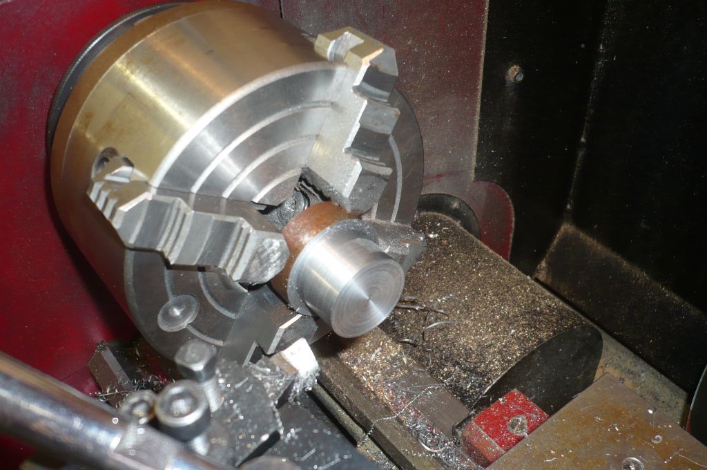
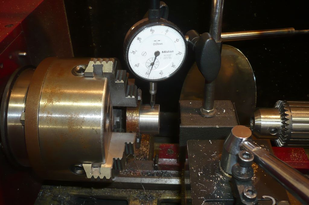
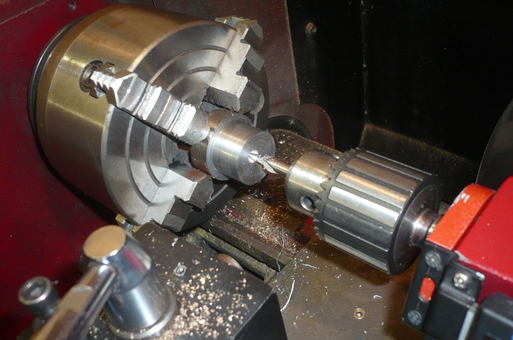
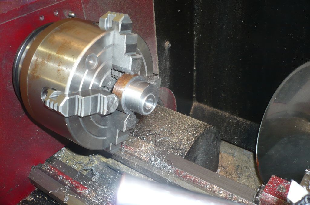
                                Made some new studs, a right fiddly job – 7/16" long, 7BA. Only six though, could have been worse. Anyway, the sheave has been finished. Because the finished engine will be fitted with the Stuart governor the sheave has no boss, this makes room on the crankshaft for the governor drive pulley.

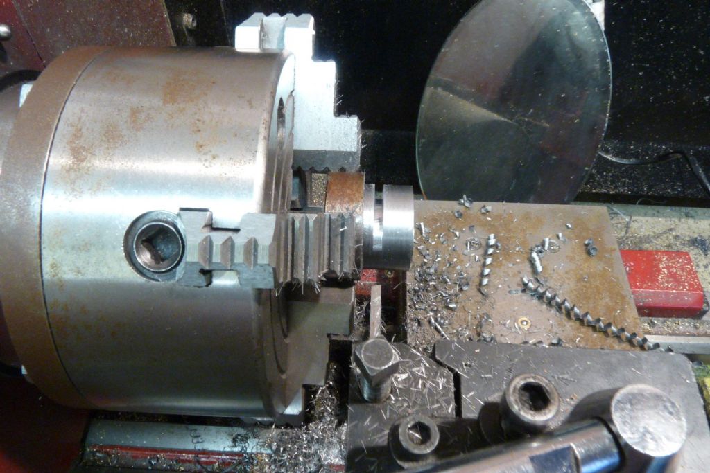
                                The sheave is turned to its outside diameter from a short length of steel bar:

                                p1030295.jpg

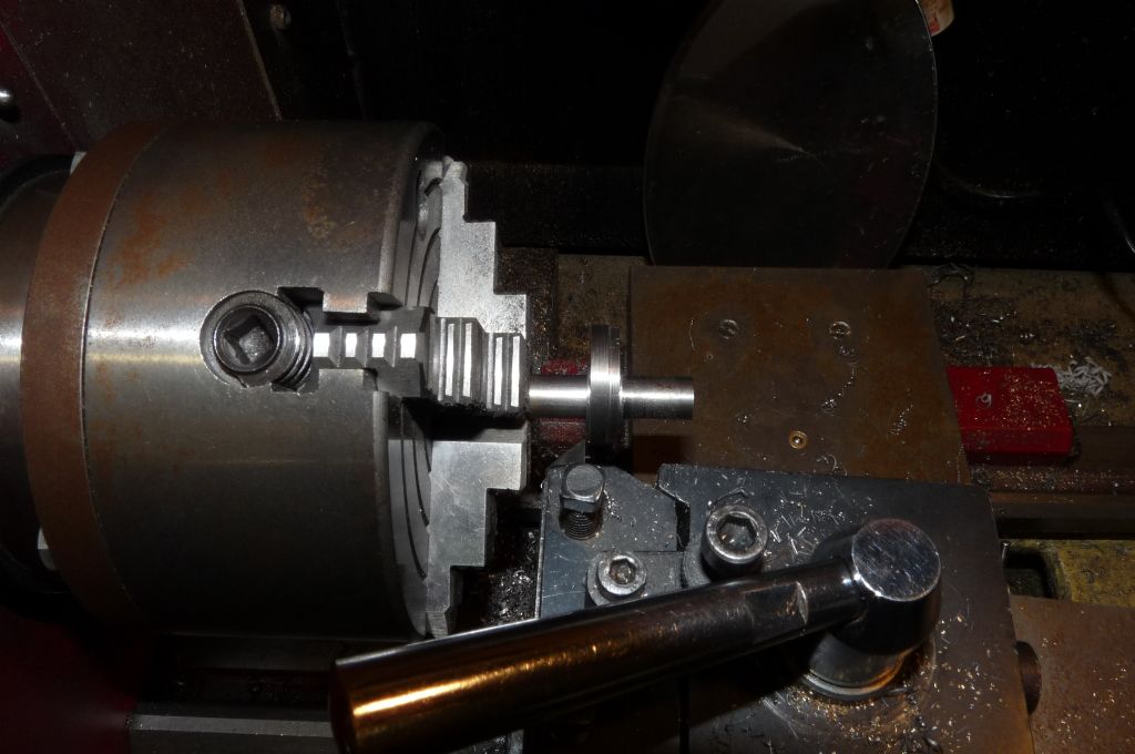
                                Then I set the eccentric throw:

                                p1030296.jpg

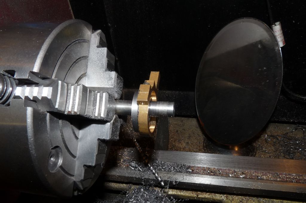
                                And then bored the hole for the crankshaft so it's nice fit, then turned the little cheek that acts as a spacer:

                                p1030297.jpg

                                p1030298.jpg

                                Next step is to part off – on the eccentric. This is advice from Harold Hall's build of the Stuart V10, the logic being that the parting tool will break into the crankshaft hole evenly around the circumference. He also strongly recommends the use of a rear parting off tool, which I don't have.

                                p1030866.jpg

                                Parting off didn't really cause any evil demons to appear, slow and steady, show no fear…

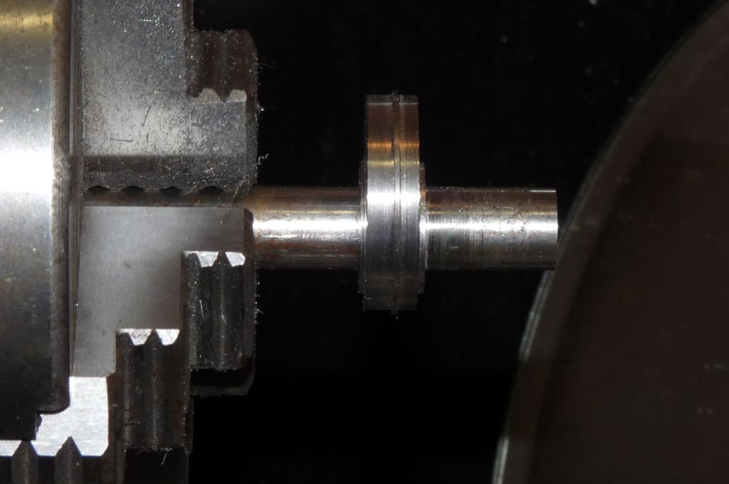
                                In order to finish off the machining, I used loctite to fix the half finished sheave onto a short length of bar, here I've already turned the first side if the sheave:

                                p1030876.jpg

                                Using the eccentric strap as a gauge to ensure the diameter is correct:

                                p1030875.jpg

                                Now the workmanship is exposed:

                                p1030880.jpg

                                The sheave is a perfect fit with the strap, nitwit put a very nice slot in the wrong place in the strap…However, it does not matter and only we know . Because the sheave has no boss now to take a grub screw, the grub screw is to be fitted in the centre (ahem) of the sheave. If you think the sheave is looking a bit of a funny colour, it's because the loctite needed getting pretty warm before it would give up.

                                p1030882.jpg

                                So that's the sheave done. Next installment will be fitting the cylinder to the table.

                                Steve

                                #196519
                                Nick_G
                                Participant
                                  @nick_g

                                  .

                                  Nice progress smiley

                                  But I would have thought having the grub screw there is going to make adjusting the valve timing damned tricky and time consuming having to take the sheave off each time so an adjustment can be made.

                                  Nick

                                  #196525
                                  Steve Withnell
                                  Participant
                                    @stevewithnell34426

                                    Hi Nick, yep it isn't ideal, but it's a consequence of needing somewhere to put the governor drive pulley. To be honest, that how it is on the plan and I haven't bothered to think through a better option. It worked out OK on the Victoria though.

                                    I am interested in knowing if anyone has come up with a better design for mounting the governor on the Coombes – it doesn't look particularly good as planned (didn't on the Victoria either, but there is space for alternatives).

                                    Steve

                                    #197067
                                    Steve Withnell
                                    Participant
                                      @stevewithnell34426

                                      Before I crack on with any more James Coombes build pictures, here is a very useful jig I made for the Stuart Victoria.

                                      p1030901.jpg

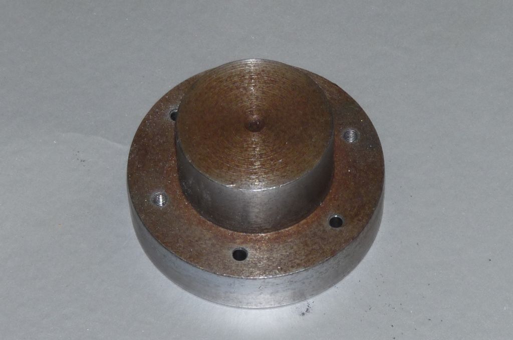
                                      The James Coombes and Victoria share the same cylinder, so the jig works for the JC too. First off I turned the spigot to the diameter I intended to bore the cylinder to. In this case that very popular metric value – 25.4mm.

                                      Since inner diameters are more difficult to measure than inner diameters, this is a simple gauge to test the cylinder bore.

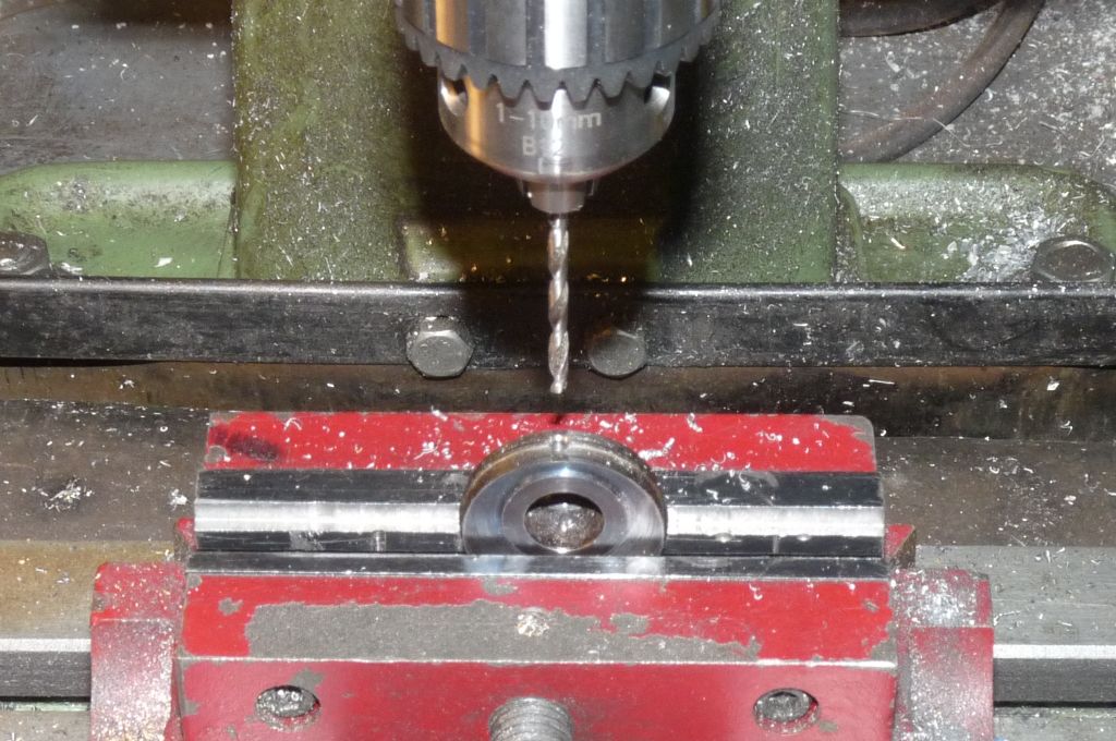
                                      Then I mounted the sigot in the rotary table and drilled 7BA tapping size holes to the PCD indicated on the Stuart plan. Key point here is that if you bugger this up, it's just a short length of steel bar, not a very nice, expensive casting. Once the holes are drilled correctly, you then have a drilling jig, which reduces the chance of an upset with the cylinder by quite a bit.

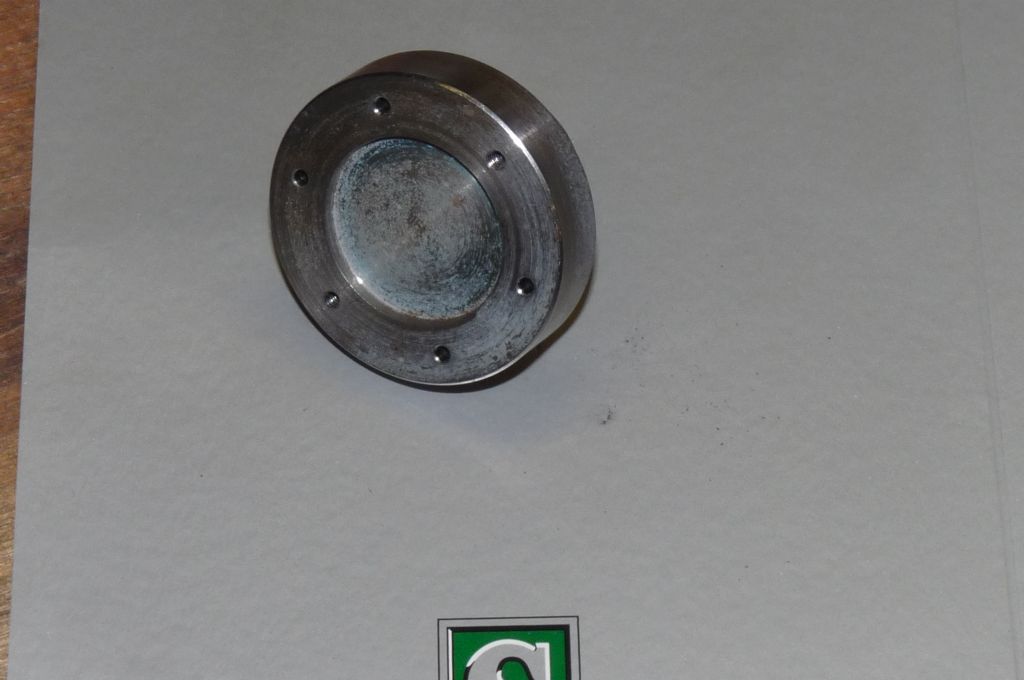
                                      Then finally, the end caps needed drilling, so to ensure they were drilled correctly, I bored a shallow recess to take the inner spigot of the end cap and could again drill the end cap in exact alignment with the cylinder.

                                      p1030900.jpg

                                      Final trick is that because the jig is quite thick, having drilled the holes out clearance size, it can be used to keep the tap straight when tapping the cylinder.

                                      Bear in mind that even if you only have one cylinder, the jig will be used twice for the cylinder and twice for the end caps and once for the boring, so it has a lot of utility for such a simple thing. The next project on my list is a twin and I will definitely be making a jig to support machining the cylinders.

                                      Steve

                                      #197068
                                      GarryC
                                      Participant
                                        @garryc

                                        Nice one Steve, I may well give that a try..

                                        Cheers

                                        Garry

                                        #197122
                                        Steve Withnell
                                        Participant
                                          @stevewithnell34426

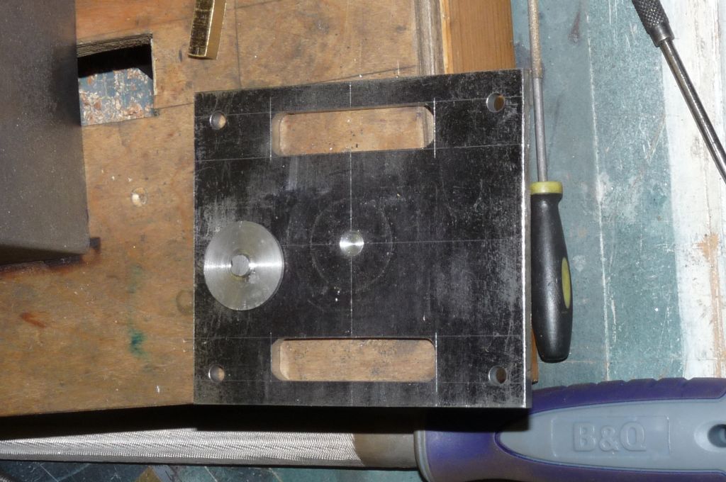
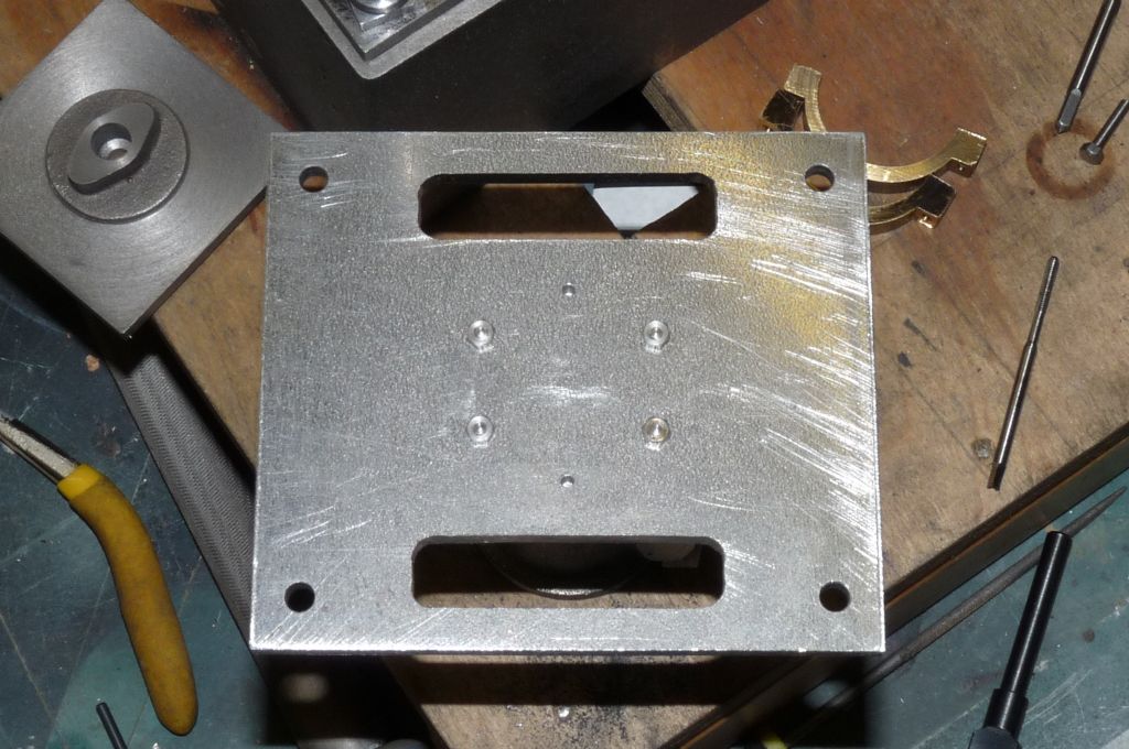
                                          Next step is to drill the "table" to mount the cylinder. If you remember, the James Coombes is a "Table Engine". It doesn't mean the engine sits on a table, like most models do, but rather that the Cylinder sits on an entablature – a table. The next challenge is to fix the cylinder square and dandy in the middle of the table, as it is the central, vertical axis through the engine.

                                          p1030285.jpg

                                          Not shown on the plan, but documented in Andrew Smiths guide to building the engine, he describes drilling a central 1/4" hole through the middle of the table, then making a little fitting which is a disc sized to the engine bore, with a turned spigot that is a push fit into the 1/4" hole. I didn't really like the idea at first and took a halfway house approach.p1030883.jpg

                                          I made a shallow 1/4" recess in the table and made a temporary jig to centre the cylinder


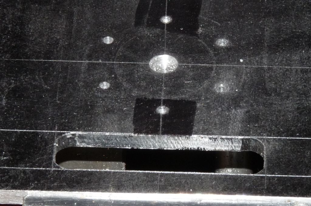
                                          Then I mounted the drilling jig over the jig so that's centred. The holes can be roughly centred against the marking on the table, but a final check is to setup to drill the rear most hole, then wind the table to the front most hole and the drill should pass right over that hole. If it doesn't, the jig needs rotating a bit. (Bear in mind the rear of my table plate is a datum and the rear edge of the vice is set to the axis of the mill).

                                          p1030886.jpg

                                          Then finally, the finished operation:

                                          p1030888.jpg

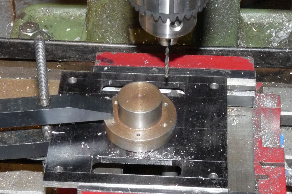
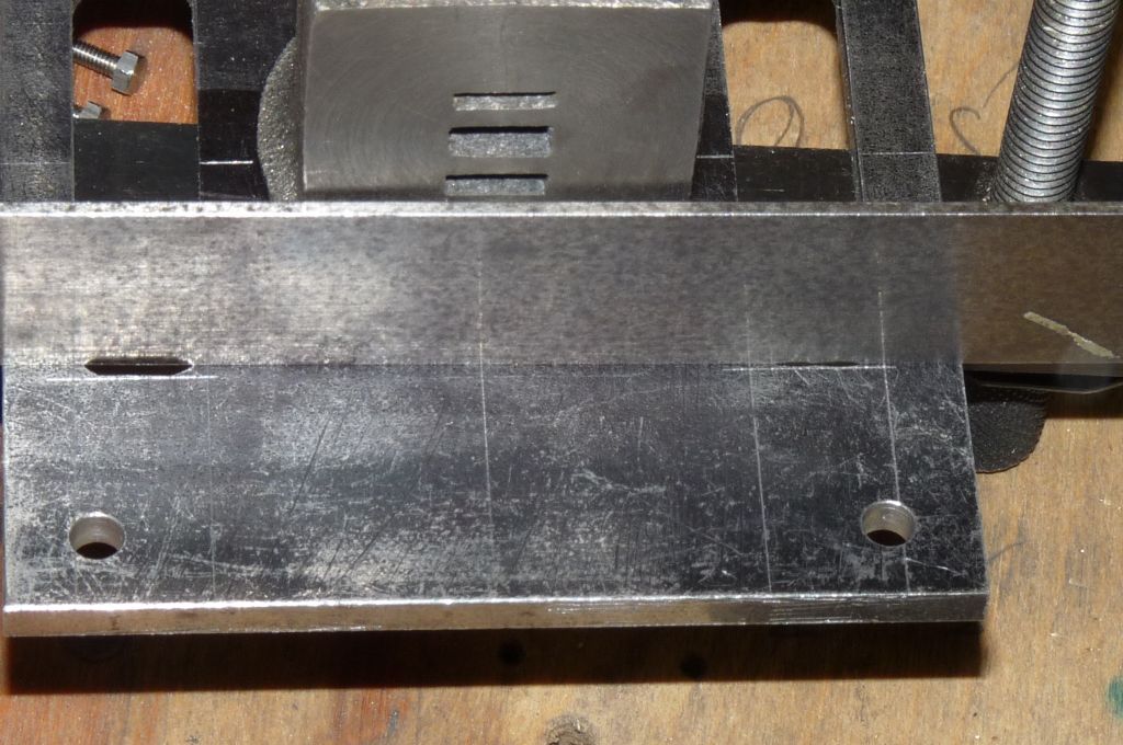
                                          The next thing I did was to drill through the table into the cylinder, the orientation is set by using a straight edge against the cylinder port face and the marking out on the table, and then clamping in down. The little jig is used again to to keep the cylinder central.

                                          p1030893.jpg

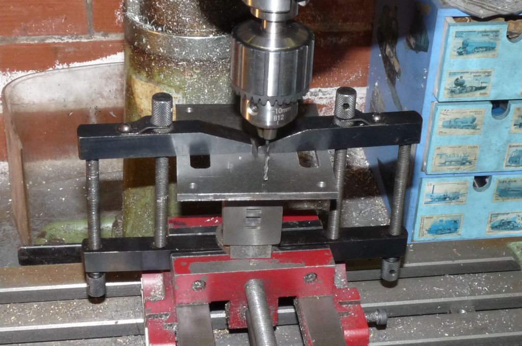
                                          Here is the work all clamped together and set up on the mill, for drilling through 7BA tapping size –

                                          p1030892.jpg

                                          Once the cylinder is tapped it can then be mounted on the table.  Two points to note here,  Stuart supply 3/8" studs,  which are too short,  so I made some 7/16" to ensure a proper hold in the cylinder (thanks to Clive on the stud length).   The clamps got in the way so I could not drill all six holes at one go,  and it had to go back on the machine to get at the final two.

                                          p1030894.jpg

                                          That's all for now folks!

                                          Steve

                                          Edited By Steve Withnell on 18/07/2015 09:54:18

                                          #197190
                                          Steve Withnell
                                          Participant
                                            @stevewithnell34426

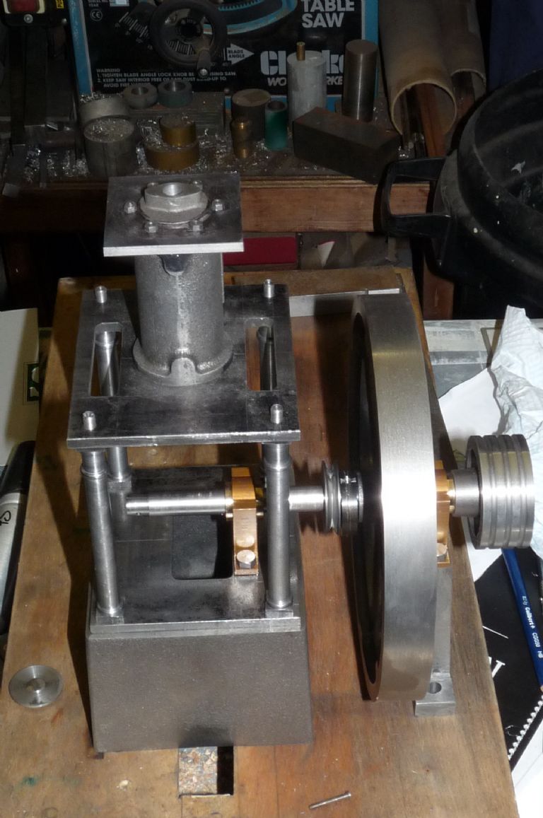
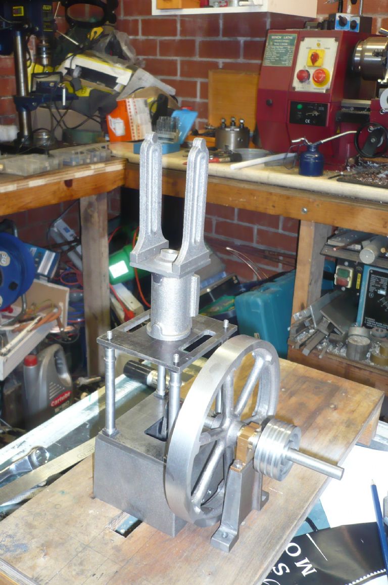
                                            So now we are here in the build:

                                            p1030909.jpg

                                            And I need to add the cross head guides (just perched on top to show the idea):

                                            p1030289.jpg

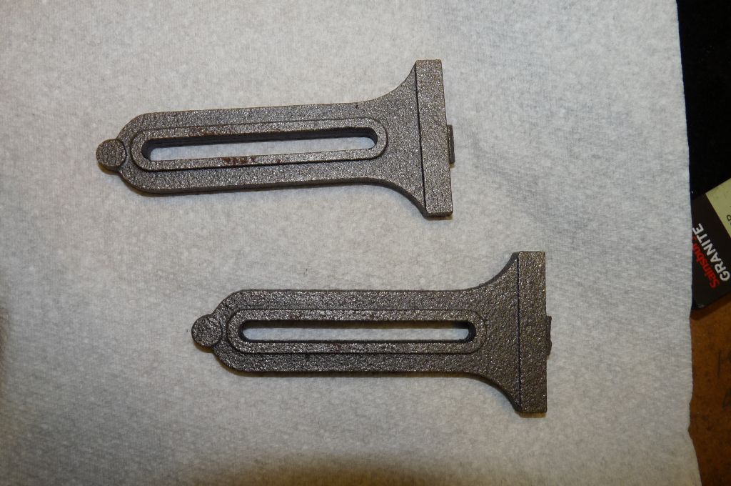
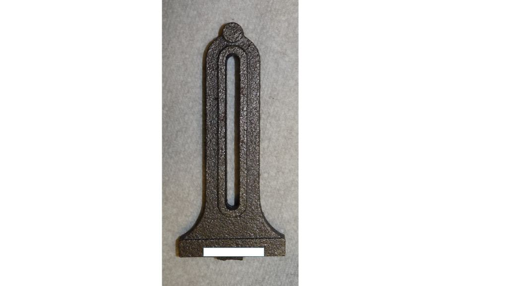
                                            What you get from Stuart in the kit are these castings. I've already had a whinge about how rough these are compared to the castings Stuart used to ship.

                                            p1030668.jpg

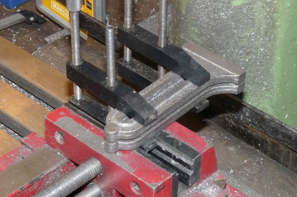
                                            First step is to give them a good fettling and get into a decent state. Then I clamped the pair together so I could drill a hole through the top and bolt them together. Difficult to see but now a lot of the rough edges have been filed flat (not optically flat, but homeworkshop amateur with a file flat)

                                            p1030905.jpg

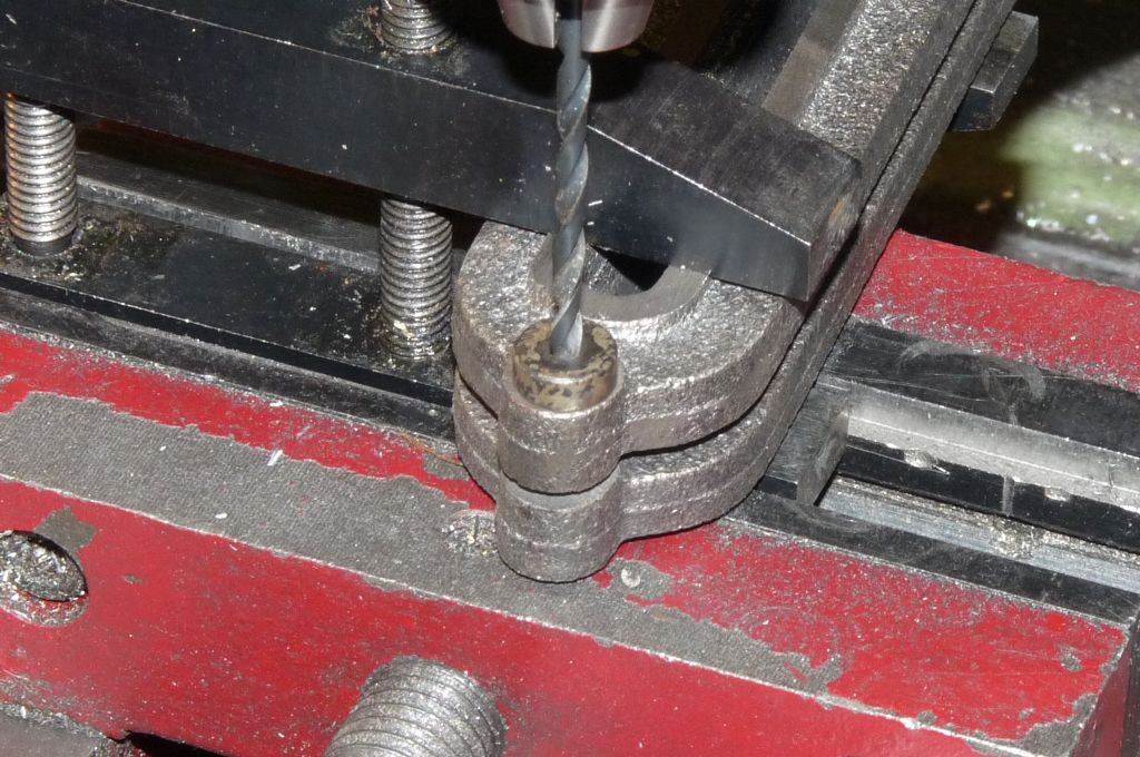
                                            I then used a filing button to centre the hole – there is no where to measure from, so the hole just needs to be centred the best I could.

                                            p1030906.jpg

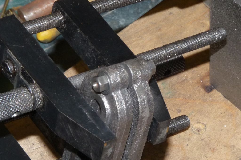
                                            Having made a short length of 5BA stud I then bolted them together so they are always aligned for the next operations.

                                            p1030907.jpg

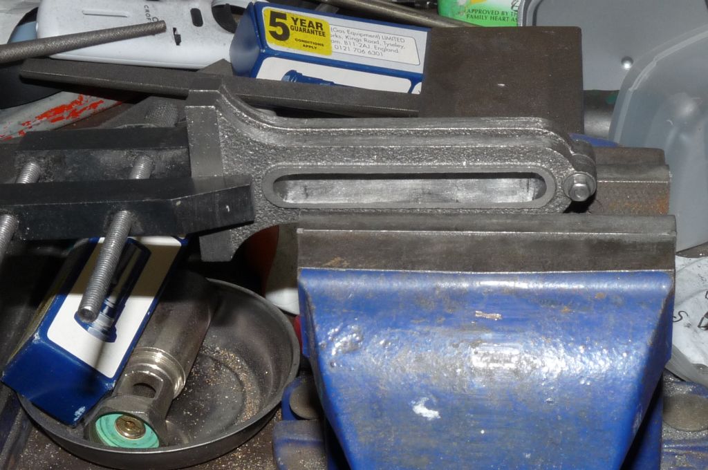
                                            The next plan was to mill out the guide slots with an 8mm slot drill, but mine are not long enough, needs a long series type to go all the way through both guides, so resorted to filing them. This is really good filling practice!

                                            p1030908.jpg

                                            As the old boss used to say, "making good progress but more to do"… Problem with the crosshead guides is that they are a centrepiece for the engine, so not only have to work mechanically, but look good too…

                                            Steve

                                            #197234
                                            Steve Withnell
                                            Participant
                                              @stevewithnell34426

                                              Still filing… I keep rotating and flipping over the guides to try and keep everything square. I've also gone a bit over size – the centre part is just slack at 9mm, should be 11/64ths. Trick is not to make that worse whilst I get the ends to size. I am pretty close to done, I've been using the shank of a 9mm drill to gauge the size of the gap, so I think now I'll make the crossheads and use them as a gauge to finish out the fiing work.

                                              I've also now worked out precisely how I should have tackled this job!   Never mind,  filing is quite therapeutic…

                                              Steve

                                              Edited By Steve Withnell on 19/07/2015 10:11:01

                                              #197240
                                              Nick_G
                                              Participant
                                                @nick_g

                                                .

                                                Filing.! You are a braver and more skillful man than I am. smiley

                                                While you have them clamped together don't forget the recess in the base. (like I did) These are needed to clear the cylinder head nuts.

                                                Nick

                                                #197249
                                                Steve Withnell
                                                Participant
                                                  @stevewithnell34426

                                                  Learning to be skilful maybe

                                                  For the base, I don't like the idea of keeping the base flat and then just making the recesses for the nuts (as per plan), it seems wrong to me. I was thinking about milling (no more filing!) a slot right across the base of the crosshead guide, half the width of the base and half the height (4.5mm) of the square section of the base. I think the guides will sit better on the cylinder cap and it may well look more attractive too.

                                                  guide.jpg

                                                  What do you think?  Maybe round the corners though.

                                                  Steve

                                                  Edited By Steve Withnell on 19/07/2015 11:45:22

                                                  #197262
                                                  Ian S C
                                                  Participant
                                                    @iansc

                                                    Steve, With the eccentric not having a boss to take the grub screw, here's my idea, make the eccentric and the governor pulley as one piece and put the grub screw through the V in the pulley. Maybe not practical, maybe is.

                                                    Ian S C

                                                    #197281
                                                    Steve Withnell
                                                    Participant
                                                      @stevewithnell34426

                                                      That's a good idea Ian, thanks.

                                                      I've made both components seperately now, but I could drill tapping size through the sheave and pulley in a couple of places, drill the sheave clearance and countersink. Then tap the pulley 7BA and screw together with a couple of c/csnk screws. The mod would almost be invisible. Also once the timing is set properly, I can still take the strap off and tighten the grubscrew i nthe sheave if I need a bit of extra bite to stop the timing slipping.

                                                      Sounds like a plan!

                                                      Steve

                                                    Viewing 25 posts - 51 through 75 (of 76 total)
                                                    • Please log in to reply to this topic. Registering is free and easy using the links on the menu at the top of this page.

                                                    Advert

                                                    Latest Replies

                                                    Viewing 25 topics - 1 through 25 (of 25 total)
                                                    Viewing 25 topics - 1 through 25 (of 25 total)

                                                    View full reply list.

                                                    Advert

                                                    Newsletter Sign-up