Moving to the Governor plan, the inlet valve arrangement is quite clear.

The components 42 and 49 are machined from a brass extrusion. Finding the vertical centre line is quite straight forward, the horizontal centre line, less so.

The elliptical section is not regular, so to find the centreline, I blacked the sides of the extrusion, then using a square on the wide flat section as a reference, I used the blade of the Sqaure to scrape a line which is then the high point of the section:

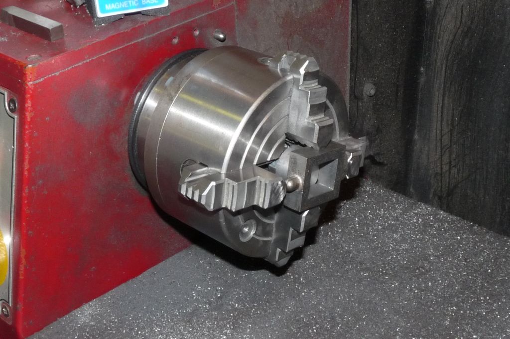
That allows the horizontal centre line to be drawn. Next step is to use the 4-Jaw independent chuck to set up the centre of the extrusion. The 4-jaw self-centering chuck can't be used, as the elliptical section is not regular. A round nose tool is used to produce the shaped section.

Having drilled and tapped the inlet, I had planned to part off the flange, but I need a new parting off blade to achieve the depth of cut, so that will have to wait for now. The plan is to drill the mounting holes prior to parting off, so that the alignment with the body of the valve would be good.
Sticking with the brass bits for now, I moved on to component 41 in the diagram above. The material in the kit is a one inch length of brass hexagon, .36 inch across the flats. The machining sequence I used was to turn the straight section first, then to use that to as a chucking spigot. I then turned the end to be threaded, drilled and reamed the through hole and then ran a die down the section to produce the thread. I used a parting off blade to create a groove between the hex portion and the end of the thread. This sequence is used to ensure the through hole is concentric with the threaded portion. Any runout is then with the straight section which will not affect the functioning of the valve.

The problem I had was that the die would not cut the full length because of the length of the taper section in the die. Turning the die over, the same taper section. Solution I used was to grind away one side of the die so that the taper was eliminated. Problem solved. The other problem is a mistake of my own making. The thread is specified as 3/16 x 26TPI, which I assumed was cycle thread (BSCY). However, it turns out to be brass thread (BSB). SInce I have the matching BSCY taps, it doesn't matter particularly.
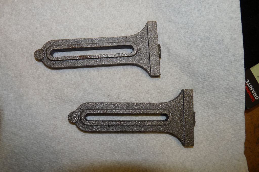
The finished part looks like this:

The next brass component is a 3/4 inch pulley that drives the flyballs in the governor.
Steve
Edited By Steve Withnell on 07/07/2014 22:20:58
Nick_G.


