Building Robinson Hot Air Engine

Advert

Building Robinson Hot Air Engine

Home Forums Work In Progress and completed items Building Robinson Hot Air Engine

Viewing 24 posts - 1 through 24 (of 24 total)
  • Author
    Posts
  • #31326
    Colin Heseltine
    Participant
      @colinheseltine48622
      Advert
      #505896
      Colin Heseltine
      Participant
        @colinheseltine48622

        Finally started my Robinson Hot Air Engine.

        Have taken the single sheet of plans and blown all the individual parts up to A3 size and printed them out. There are several builds of this engine an so I have studied these and added notes to the plans so I hopefully do not make too many mistakes. All the dimensions on the plans are in Imperial fractions.so amended all dimensions to decimal.

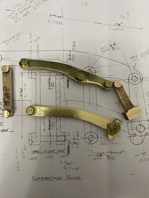
        Decided to start with the brass linkages. Cleaned up with combination of files and the die filer. Recommendations for the drop links to the regenerator and the con rods is to drill and ream them as pairs. Cleaned the back faces of all of them with file and then sheet of abranet on die filer table. Miked up the bosses on the Regen links and it was touch and go as to whether I could get them to the requisite 0.2969.  I machined the boss faces on the small Cowells mill. Basically nice and easy to see to work and in the warmth in my office.  The final dimensions were about 4 thou shy, but this will not cause a problem.

        The con rods need to be .250 thick so clamped them flat on the table, used cigarette paper to align cutter with table top and dropped the knee 0.249 to give me the .250. Repeated exercise for the second con rod.

        Then came the fun bit. Trying to superglue the pairs together. The Regen pair took two attempts and the conrods three. The first attempt on the conrod ended up in the gas hob to warm it up to separate the pair. Eventually I was happy with them.

        Back up to the Cowells Mill to clean up the sides of both pairs.

        linkages1res.jpg

        Tomorrow will hopefully drill and tap the holes for big end bolts and try and find a thin slitting saw blade to split the big ends.

        Colin

        Edited By JasonB on 08/11/2020 06:53:51

        #505933
        JasonB
        Moderator
          @jasonb

          Off to a good start Colin, Although I did not use castings for mine they are a nice engine to watch silently ticking over.

          #506100
          Colin Heseltine
          Participant
            @colinheseltine48622

            Conrod was quite an awkward thing to mount because of the taper along its length. After a bit of thought I remembered a Myford vice I have which has a swivelling section which can be used with the moving jaw moving jaw. Was able to rest it on a paralllel and clamp up tight. Then mounted the vice to angle plate on mill table. I had made a couple of filing buttons and used one to locate the centre of the small end and put in a small dimple with a drill. The Big end I had used calipers to find the center. The only way I could think to get it vertical was to use the laser edge finder to pick up the line on the vertical face and the dimple in the big end. A sheet on white paper held at 90 degrees to the conrod enabled me with a magnifying glass to centre the laser The vice needed a few light taps to get this correct. But eventually got there.

            Centralised the X axis DRO on the glued split line, and the zeroed the Y axis on the center of the rod. Used a 1/4" endmill to create flat platforms on the what would become the big end cap. Then swapped to 2.3mm drill to to drill two holes per cap ready to tap 2BA. Went to depth of 8.5mm but this turned out not to be deep enough I found a bit later. Tapped the holes to depth. Then drilled clearance hole to depth of big end cap. Then hunted for thinnest slitting saw blade I had. I had an arbor I had made for the Cowells mill and this just gave me enough depth to be able to line the blade up on the centre of the dimple in the small end. Hand magnifier and bright light needed for this. I had to remove the clamp I had in place whilst drilling to be able to use the slitting saw. Lowered the knee 1.625inches and cut of the big end cap. This was when I found the drilled holes were not quite deep enough. Was able to go round them all again with 2.3mm drill and then tap. All OK. Cleaned edges of big end cap and refitted it temporarily with some long 2BA bolts with a nut and washer fitted to pull the cap down.

            Next job drill and ream big and little end.

            Anyone who has any better ideas as to how I could have mounted this up to machine it, please shout up.

            conrod1res.jpg

            Colin

            #507114
            Colin Heseltine
            Participant
              @colinheseltine48622

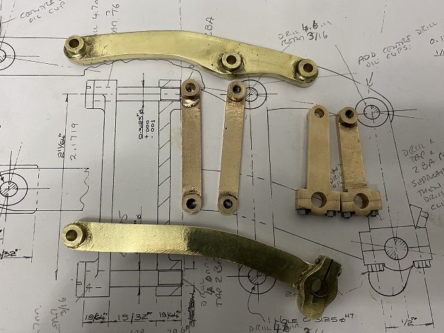
              Taken 3 days but finally got the brass linkages drill, tapped and reamed as necessary.

              The superglue trick is all very well so long as it does not separate whilst drilling. Which it did. Carefully stepping up drill sizes and it suddenly snatched separated the glue but luckily the conrod in this case stayed with the drill. My temporary big end bolts took a bit of a hammering. Carefully reassembled back in vice and continued. Unfortunately not too carefully. What I had not notices was the lower conrod had tipped slightly. Only spotted this after reaming the holes (0.250&quot and wondering why it appeared to be at an angle. Bugger :censored: Luckily was able to get the miniature boring head to bore the holes out from the required 0.250" up to just under 0.2812 (9/32&quot and then reamed 9/32". Will now have heavy duty crankpin. :D

              The two long straight links also separated the super glue and I ended up with a bent link. Judicious use of arbor press restored it to straight. I drilled/tapped and reamed these as individual links rather than as a pair.

              Everything else went well.

              One thing is certain it takes a damn sight longer to set these little things up to machine than the actual machining itself.

              toplinkdrillres.jpg

              linkscompleteres.jpg

              Now to make the pins.

              Colin

              #508330
              Colin Heseltine
              Participant
                @colinheseltine48622

                Pins for the linkages now completed along with the crank web.

                linkspinscrankwebres.jpg

                Flywheel is turned to size and drilled/reamed for crankshaft. Flywheel should be fitted with a 3/32" gibhead key. So this is my next step. Never made a key or a keyway so this should be fun. Especially as the flywheel keyway and gibhead key should have a 1 in 100 taper. I will try not to ruin my flywheel.

                Colin

                #509291
                Colin Heseltine
                Participant
                  @colinheseltine48622

                  The plans call for a 3/32" gibhead key. I did not have a 3/32" endmill for putting slot in the crank shaft so elected to go up to 2.5mm. This meant I needed a 2.5mm key. The only gauge plate I had was 1/8" so used the Stent T&C grinder (having trued up the wheel) to thin down to 2.5mm. This done was over to marking out plate to blue up and mark the shape of the key. Sawed shape out and filed the gibhead. Now needed to put the 1:100 taper. Jason has suggested to put parallels either side of vice at appropriate height, rest a thin ruler across the parallels and then raise one end by using a drill. the end of the rule rests on one of the parallels and the other end, in my case 200mm away rests on 2mm drill. This gives the 1:100 taper. This works really well. The issue I had setting this up was getting the height of the rule such that when the gibhead key was in place it only had 5/64" between jaws of the vice. Took a long time to setup, about 1hr, I have a big Bison vice and took me ages going through all my 1-2-3 blocks and parallels to get the height correct. Ended up with combination of 4 parallels/123blocks and a 20thou plastishim each side. I doubly checked the height with digital height gauge to be certain equal heights prior to adding 2mm drill to the equation (needed 200mm to get across the vice). Machined nicely but went very slowly and surely.

                  machininggibkeyres.jpg


                  Next job was to machine 2.5mm slot in the crankshaft. Crankshaft is 5" long ans the slot needs to be just over 2.8". Set up in a V block but struggled to get room for ER32 collet chuck between clamp and start position for the slot. Eventually found a suitable position but had rather more overhand than I would have liked but could find no adequate way to offer additional support to the shaft. Carefully milled out the slot, only to find key would not fit I had messed up, I had used the 2mm slotmill drill fitted 2.5mm slotmill and went over slot again.

                  cranshaftgibheadkeyres.jpg

                  Key fits firmly in slot, so pleased with that. Flywheel keyway will be Mondays job. Wife came out of hospital today haveing a second knee replacement so think my time in workshop may be curtailed a little.

                  I do have a slotting attachment for the Myford, which came from a mate of mine but have never used it. It is quite bulky and the current toolholders are designed for larger bores than 5/16", so will need to make a suitable holder and cutter. It has a tenon key on it to locate it in the cross-slide and hopefully parallel to bed travel. If I use this to take out most of the material then set the topslide at and angle to remove the very small amount needed to give the taper.

                  Colin

                  Edited By Colin Heseltine on 22/11/2020 21:48:16

                  #510453
                  Colin Heseltine
                  Participant
                    @colinheseltine48622

                    I managed to source a set of Imperial broaches, but needed to make broach guide as the one supplied was not long enough for the flywheel bore. Had fun making this as part way through cutting the the end mill decided to disintegrate. Luckily I was able to find another. Managed to carry on and finish machining the slot. I then made a support for the flywheel as it needed to be held at the same 1:100 taper. Slot in flywheel broached nicely. Its maybe little too deep (need to either take 15 thou out of bottom of broach guide (not so easy to set up) or much easier to use a thinner shim. It came with a 30thou shim. I really needed a 15thou. Reasonably happy for first ever keyway.

                    flywheelcrankkeyres.jpg
                    Used a length of 5/16" silver steel for the displacer rod. Drilled and tapped the bottom for screw to hold the displacer piston, and then drilled reamed the cross-hole at the top to connect it to linkage. I had found a really nice Eclipse 4" Magenetic V block on Ebay a few days earlier and it turned up Friday afternoon just in time to be used to hold the displacer rod for drilling/reaming.

                    drilldisplacerrodres.jpg

                    The piston boss is made from 3/4" hex brass stock. Put in 3 jaw on Myford and turned end down and then ran 2BA die up it. Made a small silver steel mandrel and tapped it 2 BA. This could then be mounted in collet chuck on dividing head on mill and the boss screwed into it. Centered the boss and zeroed the DRO's, then turned dividing head through 90 degrees and set up to drill/ream gudgeon pin hole. When drilled/reamed turned dividing head back to vertical and cleaned up the sides with 3/8" end mill and milled the centre out. Cleaned up edges and ran reamer through to clean out and frays.

                    centeringpistonbossres.jpg

                    I had made gudgeon pin a few days earlier and just needed to cross-drill for split pin. Decided this was going to be easier with tailstock drilling pad in the Cowells lathe. Drilled out 1.7mm for split pin.

                    crossdrillgudgeonpinres.jpg

                    pistonbossgudgeonpinres.jpg

                    Next job is the bearing support.

                    Colin

                    #513528
                    Colin Heseltine
                    Participant
                      @colinheseltine48622

                      Last week I machined the crankshaft bearing mount. The crankshaft can ether run direct in the casting, or the casting can bored out and a phosphor bronze sleeve inserted. I opted to use a pair of oilite bushes of appropriate size. As this was first time I had ever used oilite bushes I was not too sure of the interference fit required. In the end I reamed the casting out to 1/2" and pressed the bushes in with small arbor press. I was very pleasantly surprised when not only did the crank pass through the first bush it actually lined up and went through the second. It was a little stiff at first but after a bit of spinning the crank/flywheel round it soon freed off.

                      crankbearingmountres.jpg

                      Next item on the agenda was the three legged base. Cleaned the casting up with files and the linisher but found the edges of the feet somewhat chilled. Threw it in the 3 jaw chuck and with carbide tip was able to clean the base of the feet and also the outer radius. Still needed a slight tickle with grinding stone and belt sander to tidy up.

                      Moved across to the mill sat feet on a piece of 1/2" MDF and clamped down across the top but leaving access to firstly center the base under the quill (using centering indicator) and then to drill and tap the holes for 0BA studs for the main body of the engine. Mounting holes also drilled in the feet. Use the Bolt Circle settings on the DRO to get position. I made this difficult for myself as I did not position the casting very squarely. It took me about ten attempts to get the hole to position over the foot correctly. I had to shrink the suggested PCD slightly but only after I had worked out where the bolt hole software wants to start its first hole from. Eventually it transpired it starts from the left hand side of the circle. As I had three feet 120 degrees apart I finally ended up with a start position of 28.5 degrees. Trial and error and reset the parameters a number of times, but came out okay in the end.

                      The hot end casting was next. Mounted in 3 jaw chuck and used the revolving center in the tailstock to prevent it moving. Cleaned up the outside and the lower lip of the flange. Very carefully cleaned the perimeter of the flange as this was only about 20 thou from the jaws. Cleaned up most of the base prior to removing the revolving centre and doing a final pass. Turned round in the jaws and bored out to 3.4" for the regenerator piston. This is an ASDA salmon can. Put groove in top of the flange for 4" ID 'O' ring. Didn't quite get calculations correct for this and had to expand the groove outwards a little.

                      base&hotendres.jpg

                      Next job will most likely be dismembering the salmon can and converting it for its new function.

                      Colin

                      #514599
                      Colin Heseltine
                      Participant
                        @colinheseltine48622

                        Decided to have a go at the Regenerator/Displacement piston. Decided to try the ASDA Salmon tin.
                        I did not want to cut the tin open and have it deform in any way. Mounted it rim side down in the large indexer and centralixed it with coax centering tool. I did not want to use end mills or wood hole cutters and then remembered I had bought a set of Parkside diamond hole cutters from LIDL a year or so ago.

                        diamondcuttersres.jpg

                        Had a look at these and they were nicely sized so picked 1/2" one and put a hole in the centre. It cut a nice clean hole. Off set the indexer by 1" in the Y axis, set indexer to 72 degrees and worked my way round till I had a ring of 5 equidistant holes.

                        holesinregenres.jpg

                        Then removed the juice the salmon was packed with with a small syringe with a large bore needle.

                        juiceextractres.jpg

                        To ensure that the hole in what was to become the bottom was perfectly centered I put a long centering drill in chuck, went down through the salmon layer till touched the bottom of the tin. As soon as I felt the drill go through I stopped. Removed the tin from the chuck and looked at bottom of tin. Realised I had cocked up slightly. The base of the tin had sprung and and although I had stopped as it broke through it had sprung up and the centre drill had left a larger hole than required. :ThumbsDown: Luckily I had prepared for such eventualities by buying a second can of salmon. :ThumbsUp:

                        Repeated the exercise only this time used a 3.5mm drill to give hole size required.

                        Turned the can over and repeated to put another 5 holes but offset 36 degrees to the set on the other side.

                        Then spend 15 minutes removing the contents of the can and throwing in the bin. I did not think the cats would appreciate swarf from the diamond cutter in their tea. <img decoding=” src=”http://www.modelenginemaker.com/Smileys/default/smiley.gif&#8221; title=”Smiley” />

                        regenbottomres.jpg

                        regentopres.jpg
                        So now we have a regenerator/displacement piston with no soldering (silver or otherwise). :cartwheel: I now need to turn down the rod on which the displacer is fitted and make a small shouldered washer for the top of the can. Will also put a thin sleeve inside to separate the stainless steel mesh from the rod location to aid assembly.

                        Next step is power cylinder.

                        Colin

                        #514932
                        Colin Heseltine
                        Participant
                          @colinheseltine48622

                          To ensure displacer can be assembled and dis-assembled easily I decided to insert a sleeve in the centre with a support bush at the top and turn down the diameter of the rod to .250.

                          displacercomponentsres.jpg

                          The sleeve also prevents the can from being crushed and miss-shaped when fixing screw inserted from the underside.

                          displacerassembledres.jpg

                          This worked okay and then assembled it and filled with two stainless steel pan scourer pads.

                          displacerwithssfillerres.jpg

                          Colin

                          #516009
                          Colin Heseltine
                          Participant
                            @colinheseltine48622

                            Well it's taken best part of two days but now have a power cylinder.

                            Once the base was flat and squared up drilled the two mounting holes and the two transfer port holes which allow air to pass between the power cylinder and displacement cylinder via the main body.

                            powercylbaseres.jpg

                            Then over to the large 4 jaw chuck. I trued the cylinder up using the outer surface of the cylinder and then checked that the two machined faces on the base were square (in both directions) to the face of the chuck. Faced the end of the cylinder, it was a little on the hard side. Boring the cylinder was taking around 20 minutes for a return journey as I had it on the slowest feed I could get. Again the first 1/8" was hard. Gradually worked way out to just under the requisite 2.25" and left it overnight and finished off this morning.

                            borepowercylres.jpg

                            Turned cylinder round and fitted in 3 jaw chuck to machine the governor end. The 1" diameter hole which passes through to the main bore just cleaned up with about 20 thou to go. The larger diameter bore then put in to a depth about 10thou past the pair of transfer port holes.

                            boregovendpowercylres.jpg

                            Over to mill to face of the governor flange and drill/tap the fixing holes.

                            facinggovflangepowcylres.jpg

                            Finally drill the 3/16" hole for the linkage rod in the two flanges on the top. Was hoping to have plain hole one side and tapped hole the other but had to abandon this idea. The holes were bugger to drill as the material was hard, started to tap the lower hole but decided discretion was the better option and stopped before the tap snapped in the hole. Drilled the hole out and passed a 3/16" reamer through it.

                            powercylinderres.jpg

                            Colin

                            #516544
                            Colin Heseltine
                            Participant
                              @colinheseltine48622

                              I was doing really well, the piston was almost complete, fitted beautifully, just had to face off the boss on the top. Put in 3 jaw on Colchester, coke can shim to protect it. Really slow 5 thou DOC to clean up the face. Tool dug in and threw piston out of chuck. :censored: :censored: :censored: It changed shape slightly. :censored: :censored: :censored: Scrap <img decoding=” src=”http://www.modelenginemaker.com/Smileys/default/sad.gif&#8221; title=”Sad” /> after taking my time. Ordered new casting of GC.

                              dinkedpiston1res.jpg

                              dinkedpiston2res.jpg

                              Was going to abandon workshop and read a book but decided to make the governor plunger. At least that bit went okay.

                              governorres.jpg

                              Happy New Year to you all.

                              Colin

                              #517040
                              Colin Heseltine
                              Participant
                                @colinheseltine48622

                                Having spoken to Graham from Alyn Foundry he suggested that I cook the damaged piston in the furnace as this can grow the casting. So programmed 800 degrees and then soak of 20 minutes then gradual cool down.

                                cookingpistonres.jpg

                                Having cooked the piston as per Grahams suggestion I was amazed by how much it had grown. Just under 10 thou on diameter. Made a 1/2" mandrel with 2BA thread and stuffed it in the collet chuck and screwed piston on. It looked pretty true all things considered so proceeded to cleaned up the piston boss and face and then turned diameter back down to 2.2495. It cleaned up reasonably well. Can still see couple of marks in it, but going to go with it for now.

                                movingbitsres.jpg

                                Last piece to machine is the main platform. Will try this on big lathe tomorrow.

                                Colin

                                #517055
                                JasonB
                                Moderator
                                  @jasonb

                                  Starting to come together now, good result with the piston.

                                  #517058
                                  Colin Heseltine
                                  Participant
                                    @colinheseltine48622

                                    Jason.

                                    Many thanks. Graham is sending me a new piston casting, but I may well try it with this resurrected one. Not sure of the best way to lock the piston on the little end. I have not made the thread long enough to use a lock nut, although I guess I could reduce the boss some more to expose enough thread for a lock nut, or just lock-tight it in place.

                                    I have put off doing the main platform till last. Think this is the bit that is worrying me the most.

                                    Colin

                                    #517727
                                    Colin Heseltine
                                    Participant
                                      @colinheseltine48622

                                      Fettled the main casting and went to have chat with friend, Tom, who had his own engineering business for last 4 years.

                                      fettledmaincastingres.jpg

                                      Had a chat about brazed carbide tooling and borrowed a spare green grinding wheel of him. His view was to mill the casting rather than turn in lathe. Chatted about milling cutters and appropriate speeds. Came back and set up in mill with flat side down resting on two parallels with couple of bits of thin card to get level. I had what should be a nice 4 tip facemill cutter which fitted in my large Clarkson collet. Ran it nice and slow but had a very rough, almost grooved, finish. :ThumbsDown: Could not work out what was wrong :headscratch:b and Tom came up for a look and bought his spare R8 3 tip facemill. Swapped over to this and achieved a beautiful finish. <img decoding=” src=”http://www.modelenginemaker.com/Smileys/default/smiley.gif&#8221; title=”Smiley” />

                                      facingundersideres.jpg

                                      Looked at my facemill and found that for some reason two of the opposing tips were slightly lower than the other two. Gave it a quick clean and it appeared a little better, but is now awaiting complete disassembly and a visit to the ultrasonic cleaner.

                                      With a decent finish on the circular underside the casting was turned over and the top face milled. This machined really nicely but needed a little more machining off than I expected to completely clean up. Finished off with a 1.5thou cut with about 1/2" stepover.

                                      cleaninguptopmaincastingres.jpg

                                      facedtopmaincastingres.jpg
                                      Really pleased with the finish achieved. Its about 20thou undersize on height but this should not cause any problems.

                                      Slowly looking like an engine.

                                      almostlookslikeengineres.jpg

                                      Next step is a bit of boring, drilling and tapping.

                                      Colin

                                      #518295
                                      Colin Heseltine
                                      Participant
                                        @colinheseltine48622

                                        Setting of the main casting in the 4 jaw chuck was fun. By the time it was centred on the lower periphery the the casting missed the lathe bed by about 1/8". Used a tailstock revolving centre to help hold the casting against the chuck jaws. I was running at lowest speed 54rpm as did not like the idea of casting spinning too fast and having to take interrupted cuts. The only downside is the bearings are very very noisy on that particular gear. I felt the next gear up which is a lot quieter was a bit too fast for my liking (85rpm).

                                        Trued the face up and then bored out the cylinder. Took it out to 3.35inches and then removed tailstock center to enable me to measure with internal mike as I took next few cuts to 3.4". Just before took the last cut I faced the inside top face.

                                        truingfacetoboreres.jpg

                                        Centred, drilled and reamed the 5/16" hole for the displacer rod.

                                        Put the tailstock center back in and then machined the 1/16" O-ring groove on 4.1732" diameter. Finished off with a cleaning up the periphery of the casting and putting a champfer on lower edge.

                                        o-ringgrooveres.jpg

                                        Off to the mill to use the DRO's hole positioning feature to do the three holes to mount to base.

                                        In order to position the holes to fix the power cylinder and the bearing mount, all the linkages etc are assembled and placed on the main casting. The linkage to the displacer rod needs to be set vertical and this then positions the power cylinder which is clamped in place. The bearing mount is then moved around until the whole assembly moves easily and does not jam up or get stiff in any position. When this is achieved the bearing mount is clamped in place. The holes are located on the main casing using transfer punches through the power cylinder and the bearing mount.

                                        clampfordrillres.jpg

                                        Just need to source some small headed 0BA and 2BA bolts to fix the two components.

                                        almostthereres.jpg

                                        Then have a choice: test then paint or paint then test.

                                        Colin

                                        Edited By Colin Heseltine on 07/01/2021 22:53:06

                                        #518770
                                        Colin Heseltine
                                        Participant
                                          @colinheseltine48622

                                          Opted for paint then test.

                                          All masked up today and painted.

                                          masked&primedres.jpg

                                          Base and hotpot then cured in furnace for 1hr. The other parts all went in the kitchen oven. Paint said 1hr at 200degreesC. Ran it up to 100 for hour then took out crankshaft and crankweb as these locktited together and also the bearing mount with oilite bushes.

                                          cookingpaintres.jpg

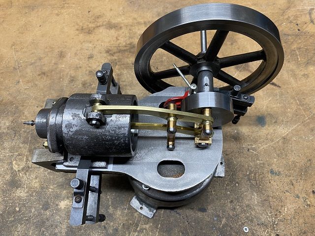
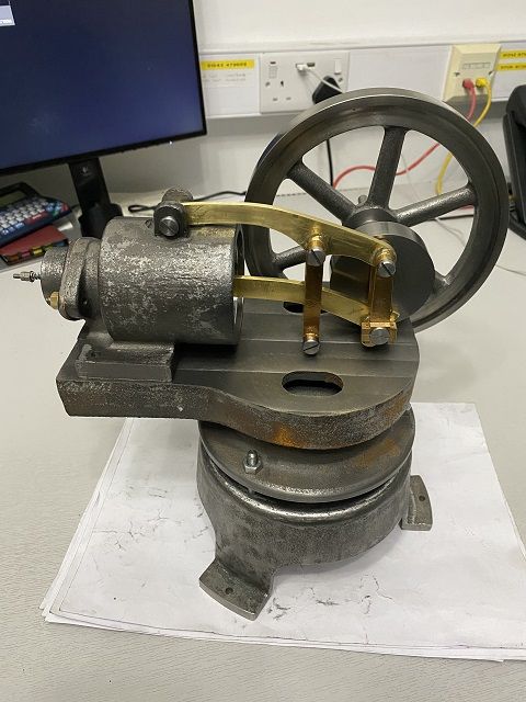
                                          Then upped to 200 for 1hr for the remainder. Once all cool assembled it all. Only one minor cock up. I had drilled the hoes in the power cylinder 2BA and they should have been for 0BA. So quick trip to the drill to open them up.

                                          allbitspaintedres.jpg

                                          completeres.jpg

                                          Then proof of the pudding, does it work. Yay, it does. :cartwheel: Not for long as was trying it on the kitchen gas cooker. The small burner was quite not hot enough and the next size burner put flame everywhere. Took a fair few spins. Will have another go in morning when cooled and this time will fill the casting water jacket.

                                          Hopefully it will loosen up a bit more as keep going.

                                          Colin

                                          Edited By Colin Heseltine on 09/01/2021 22:15:43

                                          Edited By Colin Heseltine on 09/01/2021 22:26:32

                                          #518866
                                          Colin Heseltine
                                          Participant
                                            @colinheseltine48622

                                            Second proper run this morning. Still on cooker burner. Took about 15-20 spins before it started to run, but then kept going for 40 minutes till I stopped it.

                                            Really pleased how quiet it is. :cartwheel: :cartwheel:

                                            Colin

                                            Edited By Colin Heseltine on 10/01/2021 13:55:43

                                            #520262
                                            Colin Heseltine
                                            Participant
                                              @colinheseltine48622
                                              Having finished oak base for the engine and piped up a ceramic burner I gave the engine another run.
                                              Ran the burner with a No.5 jet. With the gas turned as low as possible I ran the engine for 5 1/4Hrs without any stops or issues.
                                              Will try the no.3 jet tomorrow, but was not sure I was getting any gas through this one.
                                              Colin
                                              #520269
                                              Peter Spink
                                              Participant
                                                @peterspink21088

                                                That's very nice, lovely job! yes

                                                #520276
                                                pgk pgk
                                                Participant
                                                  @pgkpgk17461

                                                  Very nice!

                                                  Is it just me or does it say die filer to anyone else?

                                                  gk

                                                  #520277
                                                  Colin Heseltine
                                                  Participant
                                                    @colinheseltine48622

                                                    See what you mean. I had not thought of that until you said.

                                                    Colin

                                                  Viewing 24 posts - 1 through 24 (of 24 total)
                                                  • Please log in to reply to this topic. Registering is free and easy using the links on the menu at the top of this page.

                                                  Advert

                                                  Latest Replies

                                                  Viewing 25 topics - 1 through 25 (of 25 total)
                                                  Viewing 25 topics - 1 through 25 (of 25 total)

                                                  View full reply list.

                                                  Advert

                                                  Newsletter Sign-up