I am a new member and am about 1/2 way through building a Rob Roy locomotive. I have some problems because poor quality of drawings and need some consultation.
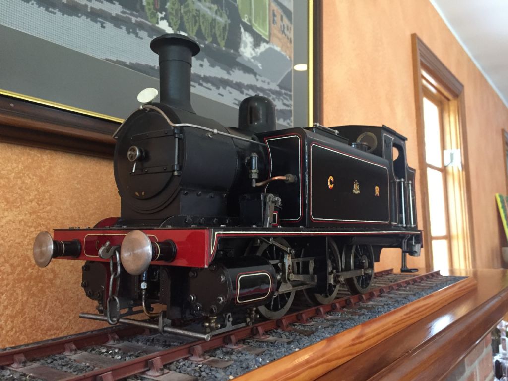
I built a Rob Roy about 30 years ago and added drain cocks at the time. Although a long time ago let me know the problem and I'll see if I can recall the details. The engine's sat on our mantelpiece and I still have the book and drawings so can probably figure it out.
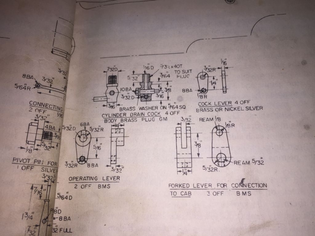
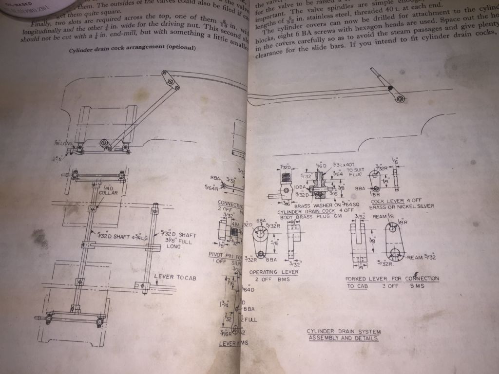
Hello Steve and thanks for your reply. My copy of the Rob Roy book has a poorly printed version of the drawings for the cylinder drain cocks. The linkage i think i can figure out. But here are my uncertainties: btw i refer to the drain cock body, the valve stem, which is turned to open/close the drain, and the cock lever, which actuates the valve stem.
1. Diameter of the valve stem? And what is the size of the hole in it?
2. Where the cock lever attached to the valve stem: a square hole in the lever, and file the end of the shaft square to fit?
3. Does the cock drain downward, i.e., straight thru, or is there a side tube directing the flow to the side?
Any help will be much appreciated. Many thanks in advance!
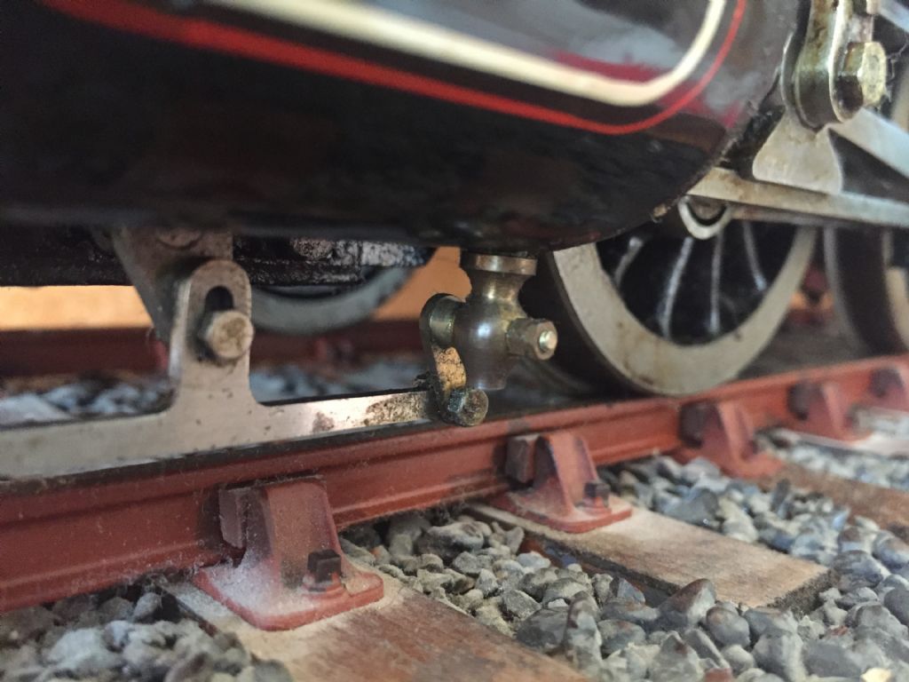
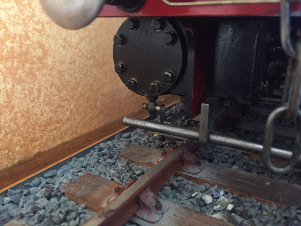
Am going to try and attach a few pictures that will hopefully be of help, but if anything isn't clear (or if you have other questions) then don't hesitate to ask. In direct answer to your questions however:>>
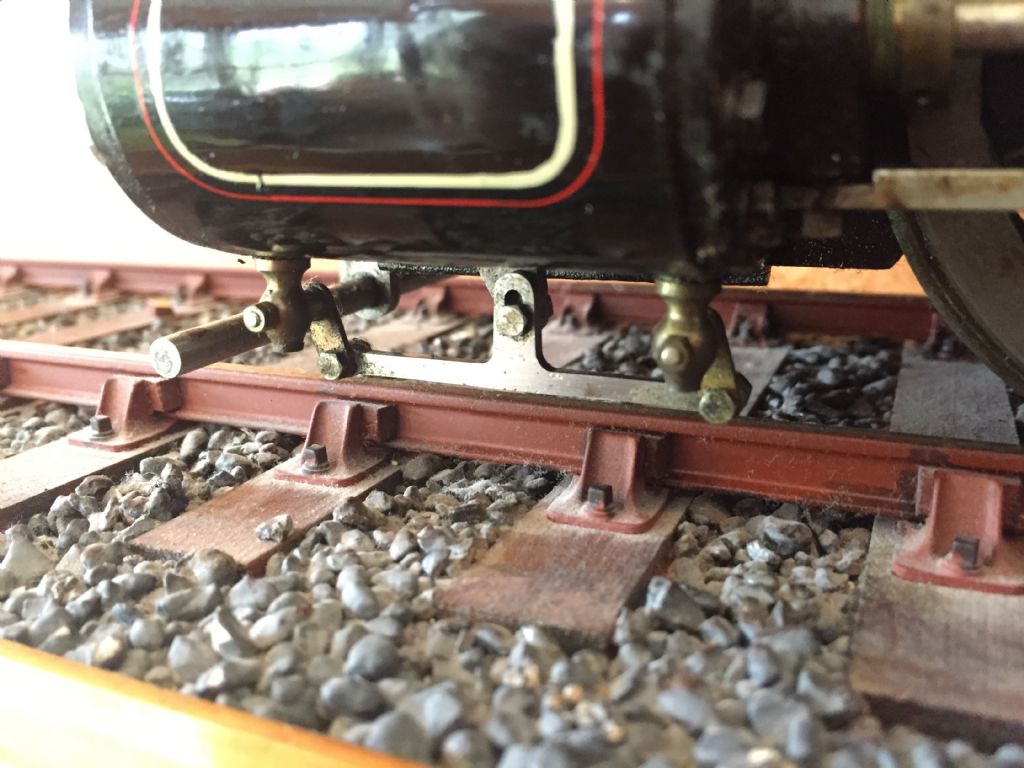
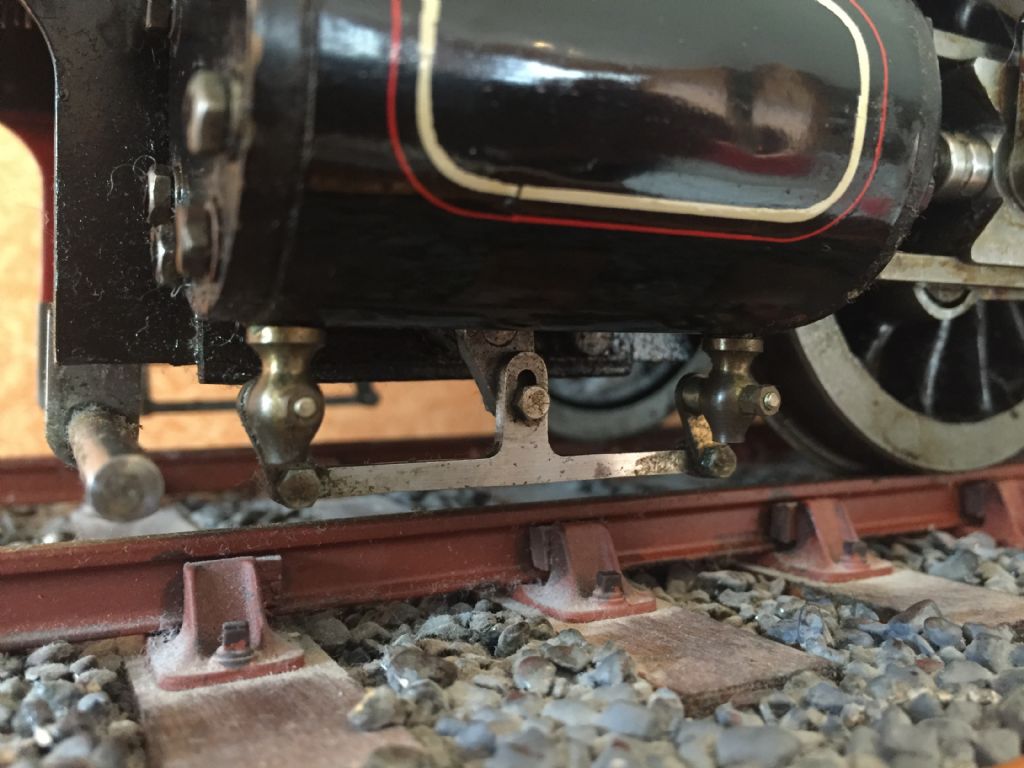
1a. Valve stem – I made mine from 1/8" brass. Note that it's tapered – you'll need to make up a little tapered D bit and machine your stems at the same time without changing your cross slide angle, that way the stem taper will match the hole taper. Machine a few extra tapered stems just in case .>>
1b. Valve stem hole – 1 mm is fine. I wouldn't go larger than 1/16".>>
2. The drawing is as you describe and that's what I did (and then silver soldered in place). In retrospect I see no reason why the hole needs to be square as you will be soldering anyway. Drill the drain hole through the stem after you've attached the lever arm, so that the holes are all in the same alignment.>>
3. The drawing shows it venting to the side. I didn't do that and have them venting straight downwards. It really makes no difference to their operation but the side vent is obviously more work.
Please note that there are a couple of mistakes on the drawings. The ones that come to mind are:
a) the cranked valve rod arms that clear the leading axle lie very close to the leading axleboxes and the connecting pin nuts will foul the axleboxes. I modified the pin so that it screwed into the axle-box side of the arm rather than being nutted on that side.
b) the blast pipe is too low and the engine won't steam. Experiment with some different length blast nozzles, I think that I had to raise mine about 1/2 inch or so.
Hello Steve: Many thanks for the hints and especially for the drawings and the photos of your very excellent Rob Roy. 1. The hint about drilling the valve stem while installed: a really good suggestion. 2. The photos show there is a slot where the actuating mechanism couples to the bar that moves the levers. The slot = not apparent on my drawings. 3. Your advice / warning about the eccentric coupling and the front axle: Alas, too late for that as I have already installed it and seen the collision with the horn block. Now working on a fix for that. 4. The blast pipe relocation now noted in my book however so thanx in advance for that.
I very much appreciate your help on this. If any more issues arise I'll be back in touch.
I honestly don't think the slot in the connecting arm is needed – I can't remember exactly why I made it that way but suspect I may have been concerned about the linkage binding if I didn't get the pitch centers of the drain cock levers and operating lever exactly the same. In retrospect I think I was being over-cautious.
Good luck with your build, let me know if anything else comes up.
As an update Peter, it just hit me that there are two real reasons why the slot is needed.
Firstly, and most significantly, the drawings show 1/4" centers on the cock levers and 5/16" centers on the operating lever. Hence, if built to drawings, the mechanism will bind.
Secondly, the slot allows for some leeway should the final vertical height of the draincocks with respect to the operating lever vary slightly, for example due to slight variation in the cylinder draincock boss heights and/or the final 'screwed in' position of the cocks themselves.
Hence, in further retrospect, I think it would be worthwhile repeating what I did and adding a slot to the connecting arm if you build the other arms items to the drawings. While you could change the center on the operating lever from 5/16" to 1/4" to match the cock levers you would still need to alter the vertical dimension of the connecting arm to suit. I think the slot gives more leeway for 'tolerances'.
Hello again Steve: I agree there must be a slot or it will bind. My plan is to start with a hole and then file it to a slot so as to relieve and binding.
I have unashamedly copied Alan's Rob Roy error list at the bottom of this message and can personally attest that the crosshead pump fouls the cylinder jacket, I ended up cutting away a small portion of the jacket to clear. While I didn't use different valve spindle threads, or add gland locknuts, the suggestion is good.
One other thing that comes to mind is that the mechanical lubricator linkage causes the lubricator to pump far too much oil as designed. I ended up using a slotted rather than pinned connecting arm between the crosshead arm and the pump arm, meaning that the pump is rotated by two ratchet teeth with every wheel rotation. That's still plenty enough oil to get your face dirty!
In addition to this forum you may also want to check out the Chaski.org/homemachinist/ forum (live steam) which has good information for North American model engineers such as ourselves.
Here's a cut and paste of Alan Stepney's Rob Roy error list:
"If built to the drawings (and I don't think they have been corrected yet), the valve gear and the valve spindles don't line up. The difference is 1/8" (?), and the solution is either to make a stepped valve crosshead, or to make the valve face 1/16" further out from the cylinder, and the valve spindle 1/16" higher in the steam chest. (Thanks, to Steve Papworth.)
Change the pitch of the thread on one end of the valve spindle, to allow the setting of the valves to be more easily modified.
Fit thin locknuts to both valve and piston glands.
The bottom section of the crosshead pump is too close to the cylinders.
The blast pipe is in the wrong position. Increasing the height of the blast pipe by about 3/8" seems to improve draughting.
The dome bushing on the boiler should be 3/4" diameter bore!
Your detailed comments plus excellent pics will I am sure be very much appreciated.
You have made an excellent example of a 3.5"g Rob Roy.
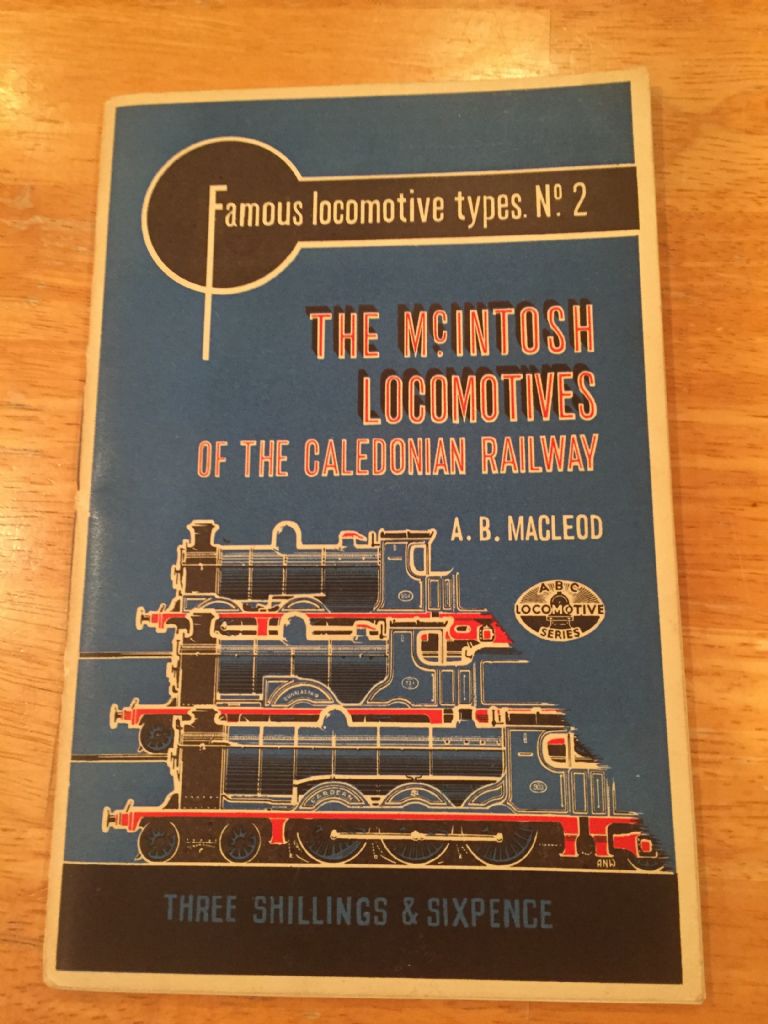
I was very pleased that you showed A B Macleod's rare book. He was a senior manager in the SR and later BR, and a great railway enthusiast both for miniature railways and fullsize especially for the Isle of Wight Steam Railway.
I met him once at Havenstreet when he was quite an elderly gentleman, and very dapper.
I hope that it's of some help to Pete and others – that's what the hobby is all about and Rob Roy is a good design in my opinion.
It's been fun dragging up the memories – the Rob Roy was my first engine – I started it at 13 and finished right around my 16th birthday if I recall correctly. It was in the students cup competition at one of the ME exhibitions at Wembley not long after I finished it, probably the 1984/5 one but I could well be wrong. I remember being in absolute awe when I spotted Martin Evans looking at it but didn't have the courage to introduce myself. An opportunity missed!
Best regards
Steve
Edited By stephen goodbody on 08/04/2017 01:32:38
Author
Posts
Viewing 15 posts - 1 through 15 (of 15 total)
Please log in to reply to this topic. Registering is free and easy using the links on the menu at the top of this page.