Building a GOTO Mount

Advert

Building a GOTO Mount

Viewing 25 posts - 51 through 75 (of 89 total)
  • Author
    Posts
  • #214068
    jason udall
    Participant
      @jasonudall57142

      Having championed the ramps previously. ..
      The ramps isn’t ” arduino” compatible any more than than any circuit anything compatible.

      The pin out fits a particular arduino model
      The ramps basically acts to breakout these pins and add some hardware interface. ( sockets for stepper drivers…three 5 amp fets…
      Five rc servo ports…and more.

      And other bits/bobs..
      If you are expecting a shield with handy-dandy library ..sorry

      Advert
      #214075
      Neil Wyatt
      Moderator
        @neilwyatt

        What I mean is RAMPS a shield for the Arduino mega (which sounds like compatible to me) and all the libraries for use with the Mega will be available as well as the Arduino IDE.

        I'll be programming mine in AVR assembler from scratch using studio 6.2. I wouldn't recommend that to others – its the path I choose because it is one of my interests.

        If the end product is of use to others I'll be willing to share it, but I'm not going to build in extra complexity because someone else might want to use it for something else in the future.

        Neil

        P.S. if you think hanging a FET of a port pin is dodgy, what about this from AVRfreaks:

        #214083
        jason udall
        Participant
          @jasonudall57142

          Neil..and what I mean is that the ramps isn’t exclusively arduino…conveniently yes but not to be overlooked if using pi. Pic.or otherwise..

          #214091
          Ian P
          Participant
            @ianp
            Posted by Neil Wyatt on 25/11/2015 11:50:40:

            Posted by Ian Phillips on 25/11/2015 09:54:11:

            Posted by Ian Phillips on 23/11/2015 21:35:25:

            Neil

            Curiosity has got the better of me, is the purpose of JP4 or the switch so that you can test the PSU?frown

            IanP

            Bumping my own post, but what does the switch do?

            Er.. turn it on and off?

            N.

            So does the PSU sense that its output is being shorted so it shuts down?

            Ian P

            #214093
            Ajohnw
            Participant
              @ajohnw51620

              Freaks is the right thing to have on the end of the name. It's interesting to put a current sense on the supply on a circuit like that but few people have anything suitable – high frequency hall effect oscilloscope probe as both mosfets will be on for short periods as they are switched. They have sort of done something about the problems that is likely to cause on the supply almost certainly adding more parts than if the drive had been done correctly.

              90nSec rise times are good at generating RFI especially with long lengths of wire on them. No need so why switch that quickly unless it's needed. The actual rise times might turn out faster that that. I'd hope that the data sheets have pulse thermal resistance info otherwise guess.

              The absolute maximum rating of the i/o pins on the processor is 40ma however the max for the chip is 200ma. They point out that these aren't what might be called real absolute ratings as long term use might damage the device or cause premature failure and later reduce them to 50% as far as the pins are concerned.

              Often on electronic items spec's are given in regions that they are expected to work in. As far as output is concerned that's 3ma but on this sort of part that can be exceeded providing the totals are looked at. The i/o conditions that the device can stand are given in condition 3&4 on page 317 of the full data. Essentially 100ma per port by the look of it and 20ma per pin – they don't mention the chip limit when driving which is likely to be 100ma max in practical terms with near 10 running the processor.

              The reason for putting something in the way when driving mosfets is the capacitance in them. It's possible for the processor pin to get volts forced onto it back through the mosfet. The ports do have clamp diodes but it looks like they are for ESD protection only as they don't specify a max current through them. Processors turn into thyristors if the port input voltage range is exceeded. A puff of smoke, a nasty smell comes out and a small hole appears in the package. Not terribly likely in this case but it can happen. Pull down resistor can help a bit even the usual 20k because it may happen when they are inputs. Looks like high side drivers ideally need pull downs as well. I'd have thought that they would build them into the chip as no one wants to add more bits. It's annoying. Lots of things need them to define what happens during reset and before the post is set to the correct state.

              John

              #214096
              Neil Wyatt
              Moderator
                @neilwyatt
                Posted by Ian Phillips on 25/11/2015 15:22:48:

                Posted by Neil Wyatt on 25/11/2015 11:50:40:

                Posted by Ian Phillips on 25/11/2015 09:54:11:

                Posted by Ian Phillips on 23/11/2015 21:35:25:

                Neil

                Curiosity has got the better of me, is the purpose of JP4 or the switch so that you can test the PSU?frown

                IanP

                Bumping my own post, but what does the switch do?

                Er.. turn it on and off?

                N.

                So does the PSU sense that its output is being shorted so it shuts down?

                Ian P

                You are making this complicated.

                Two wires from the pads go to a switch, and two more wires go from the switch to a battery.

                Neil

                #214097
                jason udall
                Participant
                  @jasonudall57142

                  Looking at that from avr freaks..

                  One…its in effect a dimmer.

                  It even sniffs the ac…so the sw could switch (both fets on) at zero crossing…
                  Bit confused over the IR sensors with switch to short out but ho hum

                  #214100
                  Neil Wyatt
                  Moderator
                    @neilwyatt

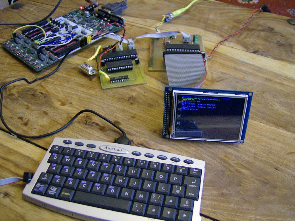
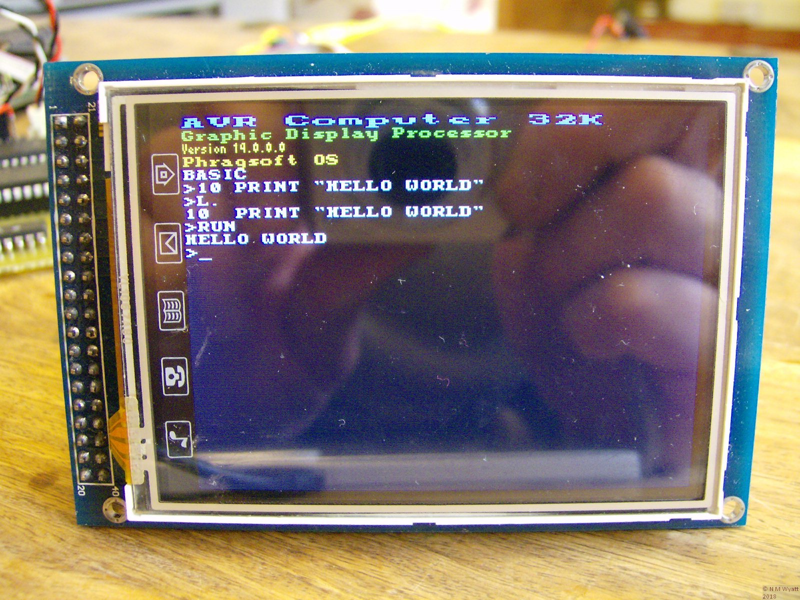
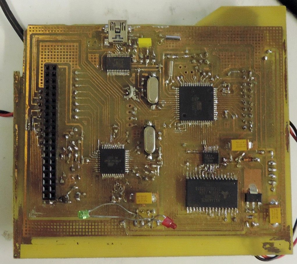
                    Whatever the datasheets say, in practice AVRs are pretty bombproof. I think I've blown one up so far. They can do quite surprising things…

                    This:

                    Plus this:

                    Makes this (actually this is an earlier version, that ran out of flash for the interpreter and more esoteric display driver functions):

                    Which does this (amongst other things):

                    Later version isn't very pretty… but it is a work in progress.

                    #214101
                    Ian P
                    Participant
                      @ianp

                      Neil

                      Not trying to make it complicated, just that it looked to me as if the two wires went to the poles of a switch. If it had said 'From Switch' or 'from PSU' I probably would have twigged.

                      As the power supply is not shown and you (sensibly) use the same symbol for all the points connected to 12v I thought 'JP4' was used for either a switch or a jumper. Presumably the normal on/off switch would be on the input side of the PSU but putting the connector on the board gives you the choice later.

                      Now, studying your PDF in greater detail I realise that all your connectors have the JP prefix.

                      Ian P

                      #214109
                      Ajohnw
                      Participant
                        @ajohnw51620
                        Posted by jason udall on 25/11/2015 16:29:29:
                        Looking at that from avr freaks..

                        One…its in effect a dimmer.

                        It even sniffs the ac…so the sw could switch (both fets on) at zero crossing…
                        Bit confused over the IR sensors with switch to short out but ho hum

                        LOL I missed that aspect and something else about it too. How the load is connected.

                        winkAs to the rest automotive stuff is produced in rather large numbers and some one some where eventually finds the flaws. Not a problem if just a few but frowned on anyway as it could cost a fortune to put right and has at times. The other aspect is that if some one spends 24 years on them most things crop up one way or another. Personally if something means adding a couple of resistors or using a better drive arrangement that might cost a couple of quid more so what especially in the hobby area.

                        Unused pins on them have the usual suggestions. Activate the internal pull up resistors or better still in some circumstances use external pull ups and pull down but direct connect to a rail is discouraged.

                        If a board was ever available I would be happy providing that any spare pins could,be used if needed.

                        Atmel do have a zero crossing application note that shows that the input pin diodes can be used as clamps via high value resistors. A rather low current as I suspected. We have had mains spikes round here that have blown dimmers and bulbs. Not sure how it would cope with that. They can be in the Kv range, more than one of them at times. MOV's have killed that problem.

                        John

                        #214116
                        Neil Wyatt
                        Moderator
                          @neilwyatt
                          Posted by Ian Phillips on 25/11/2015 16:39:28:

                          Now, studying your PDF in greater detail I realise that all your connectors have the JP prefix.

                          To be fair on me, its really just a working diagram to generate the PCB, so I'm happy to flaunt conventions or use the wrong part with the right footprint, for example. If I use a 'pin header' to get a series of pads at 0.1" spacing, it calls it a 'jumper'. Often I wire direct into them, especially for power leads.

                          It took me a while to understand 'nets', if you use these instead of a wire to join up power pins etc. then you don't need to physically join them up on the circuit diagram. This is what I have done with +5, +12 and GND.

                          The board is a right dog's dinner at the moment.

                          #214135
                          Neil Wyatt
                          Moderator
                            @neilwyatt

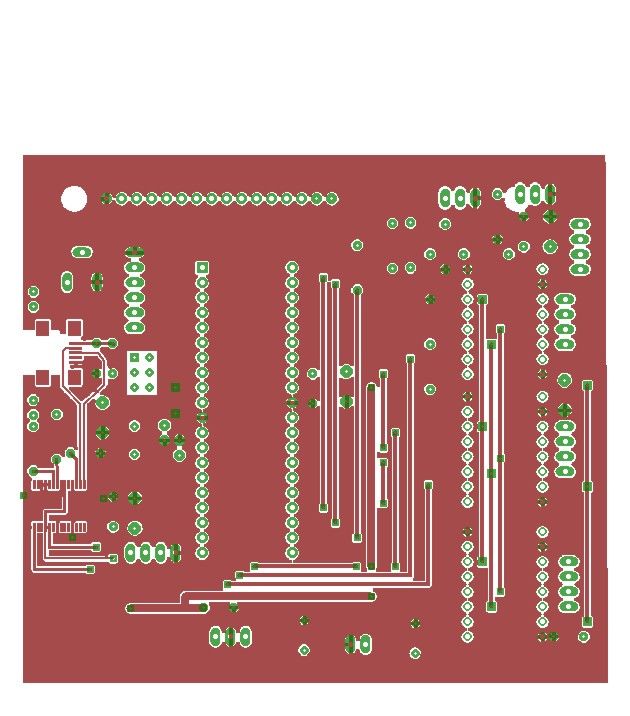
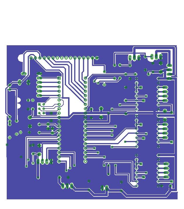
                            First stab at a PCB.

                            I will need to increase the stand off a bit as 100% accuracy in lining up top and bottom hole isn't guaranteed.

                            top_layer.jpg

                            bottom_layer.jpg

                            #222447
                            Neil Wyatt
                            Moderator
                              @neilwyatt

                              Well, I went to make the PCB today – and sods law says I only have singel-sided board!

                              Now cramming it onto a single layer.

                              #222796
                              Neil Wyatt
                              Moderator
                                @neilwyatt

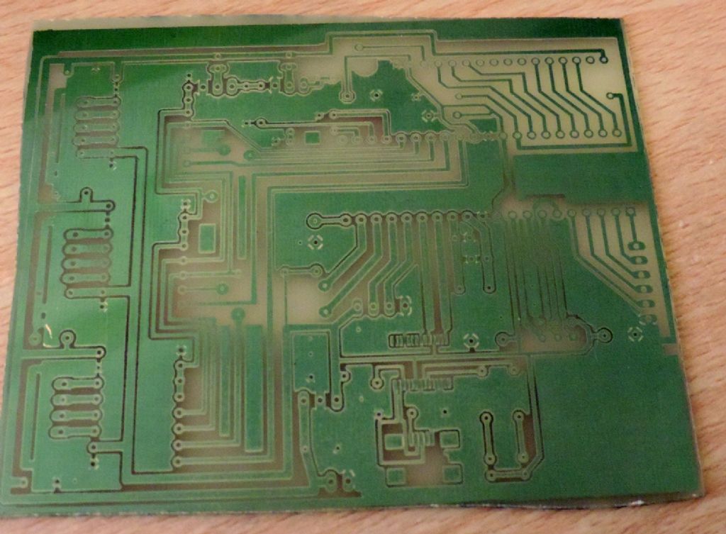
                                Single layer PCB:

                                bored.jpg

                                #232577
                                Neil Wyatt
                                Moderator
                                  @neilwyatt

                                  Quite a bit of progress, but I haven't been posting it.

                                  I have redesigned the PCB as instead if a 16×2 alphanumeric display, I will use a 64×128 green graphic display from an old project instead which can display a lot more information, including proper lists of targets.

                                  I have a nice project box made up, with five colour-coded XLR socket on the back: RA, DEC and focus steppers, guide port and dew heaters. On the front the display, chunky brightness control (for ease of use in a hurry), power and an XLR socket for the control handset. The handset is a nice small project box with five coloured push bottoms – I found out why they were cheap on eBay – the bodies have a tendency to melt during soldering!

                                  Found a lovely little unipolar stepper for focus and it had six solder pads, two joined together. I split them and it's magically become a bipolar stepper so I can run it from a polulu, but that's right down the road.

                                  Not much more I can do with hardware until get some molex connectors – I don't want a board tied to the box with dozens of wires. The steppers are fitted to their 'gearboxes' and just await wiring. So for the time being I've started on the software side.

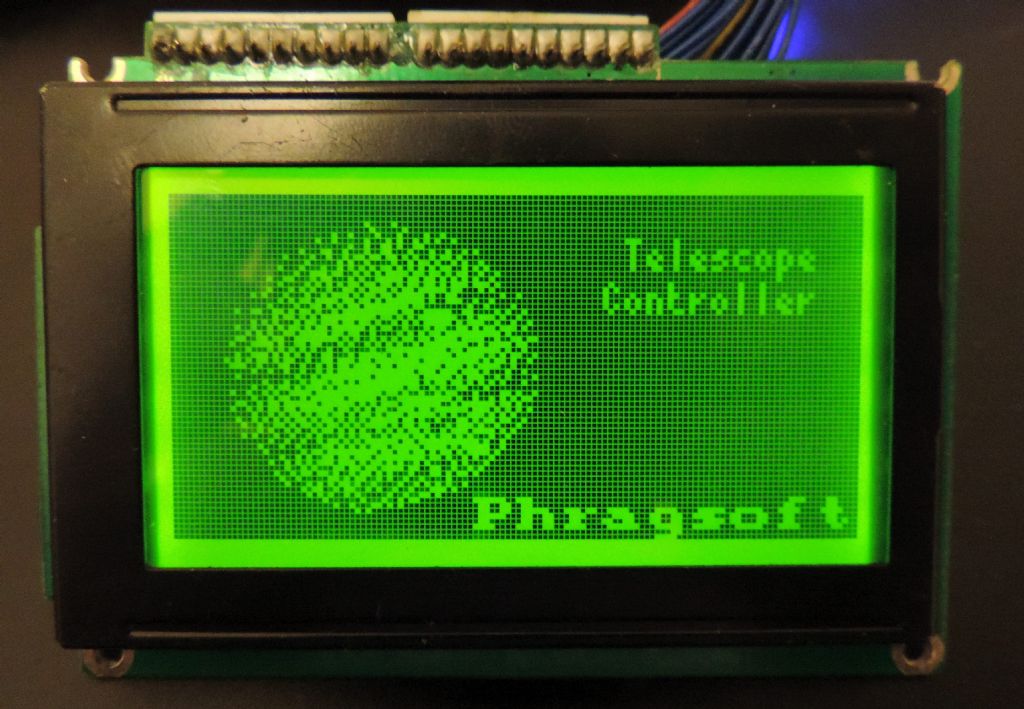
                                  Here's a pic of my 'splash screen' for now.

                                  Neil

                                  splash.jpg

                                  #237237
                                  Neil Wyatt
                                  Moderator
                                    @neilwyatt

                                    Basic box is working now, solved a problem with excess current consumption – one of the Pololu stepper boards was swallowing 65mA extra following every reset. Swapped it out and all three boards only take about 7mA each when doing nothing. Mind you the display is greedy – but the LEDs will be 'turned down' for night use!

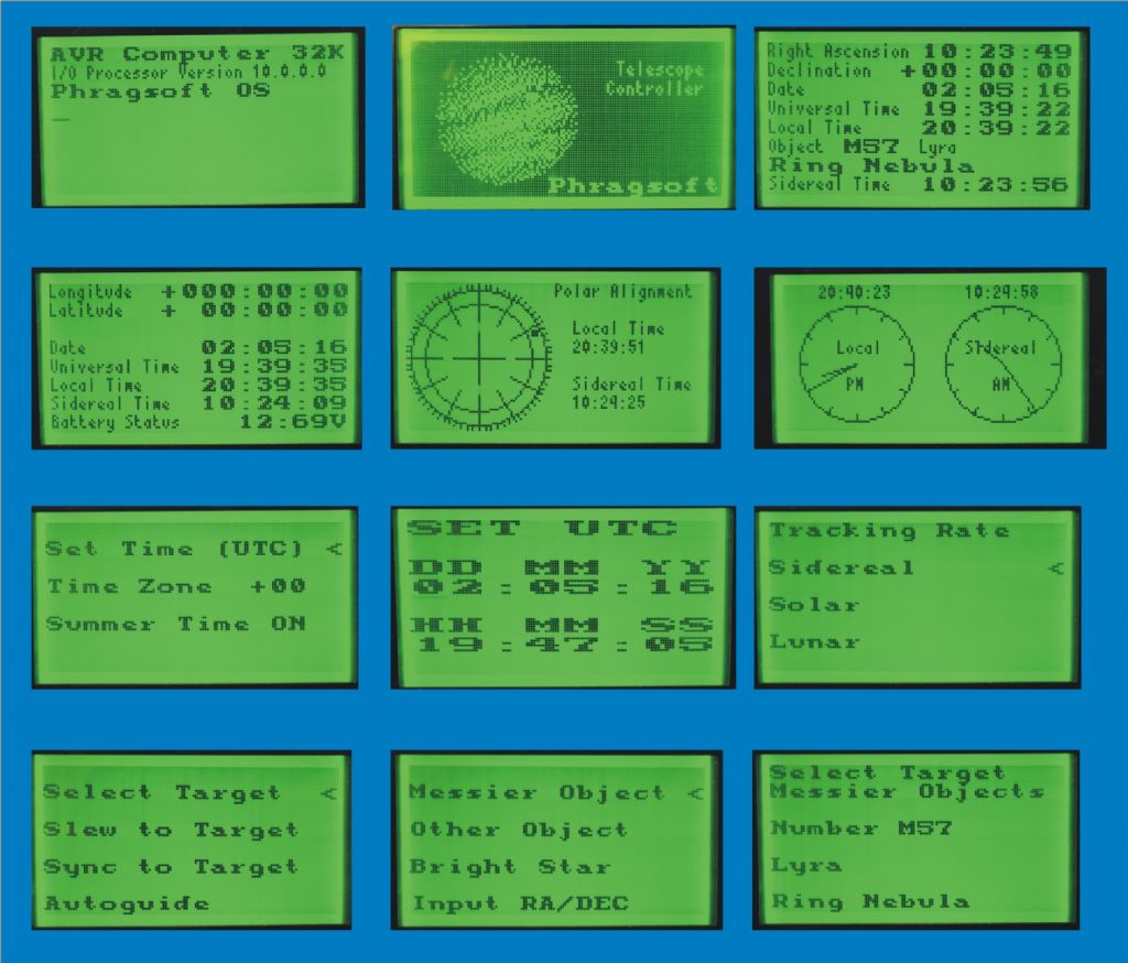
                                    Some screen grabs of work so far. Coding for calculating sidereal time to an accuracy of about 3-4 seconds over the whole century and the position of Polaris to half a degree over the same period were challenging in 8-bit assembler.

                                    I'll share some pics of the case inside when I've done a bit more wiring.

                                    Neil

                                    screenshots.jpg

                                    #237239
                                    Michael Gilligan
                                    Participant
                                      @michaelgilligan61133

                                      Impressive work, Neil yes

                                      Just one little negative point, if I may … It is generally accepted that Red is a better colour for use in a dark environment.

                                      MichaelG.

                                      #237244
                                      Bodger Brian
                                      Participant
                                        @bodgerbrian
                                        Posted by Neil Wyatt on 25/11/2015 19:13:11

                                        It took me a while to understand 'nets', if you use these instead of a wire to join up power pins etc. then you don't need to physically join them up on the circuit diagram. This is what I have done with +5, +12 and GND.

                                        I hesitate to use the word 'always', so I'll settle for 'generally' or 'usually' when I say that any connection between two or more points is called a net (some software even assigns a net name to a pin that has no connection but that's another story). The type of connection that you're referring to is often called a 'global net' or 'global' for short.

                                        Apologies for digging up an older post…..

                                        Brian

                                        #237247
                                        Neil Wyatt
                                        Moderator
                                          @neilwyatt
                                          Posted by Michael Gilligan on 02/05/2016 21:29:15:

                                          Impressive work, Neil yes

                                          Just one little negative point, if I may … It is generally accepted that Red is a better colour for use in a dark environment.

                                          MichaelG.

                                          Try finding a RED 64 x128 LCD display! Swapping out the LEDs on these waveguide -type displays isn't a trivial exercise.

                                          That said, there is a counter-argument that as the eye is more sensitive to green than any other colour, you can set a green display much dimmer than a red one and a display doesn't have to be very brightly illuminated at all to be readable at night – much dimmer than my red torch. My existing unit uses a 2×16 green LCD and it doesn't cause me any problems.

                                          And having said all that… I have a QVGA full colour display that I might drop in instead, which would do a very good job of red text/lines on a black background. But then I will probably want to add an SD card to display colour pictures of the objects…

                                          Neil

                                          #237250
                                          Michael Gilligan
                                          Participant
                                            @michaelgilligan61133

                                            Posted by Neil Wyatt on 02/05/2016 22:03:40:

                                            That said, there is a counter-argument that as the eye is more sensitive to green than any other colour, you can set a green display much dimmer than a red one and a display doesn't have to be very brightly illuminated at all to be readable at night – much dimmer than my red torch. My existing unit uses a 2×16 green LCD and it doesn't cause me any problems.

                                            .

                                            The problem is more to do with Loss [vs. retention] of Dark Adaptation.

                                            But; if dim Green works for you, who am I to argue.

                                            [You may not be popular at a typical 'Star Party' though.]

                                            MichaelG.

                                            #238035
                                            Ajohnw
                                            Participant
                                              @ajohnw51620

                                              I don't know if you are going to get into actually making a mount as well Neil but another thread reminded me of something. Many people make their own worm wheels but Celestron used another technique on my first slightly larger scope, 8" sct. They used a spur gear and drove it with a worm. It worked rather well. They also used the same arrangement on larger ones.

                                              There are several gear pitches that are very close to threads that can be easily cut. Even if there is a few thou difference it's probably going to require less lapping than a typical home made worm wheel. It would also be possible to lap the gear against others based on different primes. That's how pro telescope drives used to be made.

                                              I never had to take it apart but what I would expect to see is a worm of larger diameter than the thickness of the gear angled to account for it's helix angle.

                                              All but the most expensive mounts have lots of spur gears in them anyway so why not use one directly. There is also a fad for toothed belts at the moment but as anything will stretch to some extent they don't make much sense really. The cogs will have periodic errors anyway. Chain drive might make more sense.

                                              John

                                              #238087
                                              Neil Wyatt
                                              Moderator
                                                @neilwyatt

                                                Mount is next year's project

                                                I suspect periodic error is mainly an issue for the worm – a theoretical 10-minute sub on a 144 tooth gear would only use on tooth & space on the wheel, but a whole turn of the worm.

                                                Neil

                                                #238169
                                                Ajohnw
                                                Participant
                                                  @ajohnw51620

                                                  I like fork mounts Neil. No counterweight so far more rigid and lighter. The 8" SCT I mentioned was sold due to aperture fever. I went for 10" which is still around but have regretted selling the 8" many times so recently bought another. I'm encouraged by astro shots I have seen when used with a focal reducer.

                                                  I've also added a good quality 6" newtonian as a coma corrector will sort that out. It's fairly happy on an EQ3 with an EQ5 tripod but as I mentioned before if I added weight to the end of the newtonian I'm pretty sure it could be fork mounted and be even more stable – wink on day maybe and then look at directly driven spur gears.

                                                  I've recently sold a couple of other scopes, both apo's so the money went into more workshop gear and another lens for my Nikon V2, the long zoom for it. I'm aiming to try M 4/3 on astro but the local council recently messed things up for me. LED street lighting. It was lp sodium and a simple filter killed that completely even just being a couple of miles south of the centre of B'ham. Not much good looking north but south was fine.

                                                  John

                                                  #243825
                                                  Neil Wyatt
                                                  Moderator
                                                    @neilwyatt

                                                    Despite lack of posting, I have done a fair bit recently.

                                                    The mount now appears to be performing it's GOTO moves (just a minor issue of clockwise and anticlockwise getting mixed up, but that's a minor tweak.

                                                    More detail to follow soon…

                                                    Neil

                                                    #243948
                                                    john carruthers
                                                    Participant
                                                      @johncarruthers46255

                                                      I've fettled a few mounts that use a friction drive rather than the traditional wormwheels. No backlash, but a small chance of slipping under acceleration, which can be ramped up and down of course.
                                                      One chap in Ireland has used a large diameter small pitched toothed belt. Then there are the 'caterpillar' drives, sectors, drum/wire etc…
                                                      So many solutions to the same problem

                                                      I find the worm bearings on mass produced mounts a major source of PE, better quality bearings or angular contact bearings can make a measurable improvement. Also worm end float needs better control.
                                                      A lot of worms have their cetre holes so a conical set screw on one or both ends can help.

                                                      The belt conversion kits are a good idea too, doing away with the spur backlash.

                                                      Edited By john carruthers on 24/06/2016 08:12:48

                                                    Viewing 25 posts - 51 through 75 (of 89 total)
                                                    • Please log in to reply to this topic. Registering is free and easy using the links on the menu at the top of this page.

                                                    Advert

                                                    Latest Replies

                                                    Viewing 25 topics - 1 through 25 (of 25 total)
                                                    Viewing 25 topics - 1 through 25 (of 25 total)

                                                    View full reply list.

                                                    Advert

                                                    Newsletter Sign-up