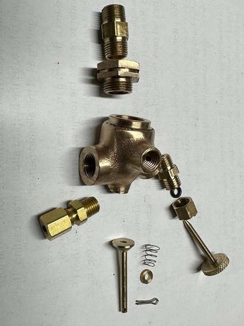
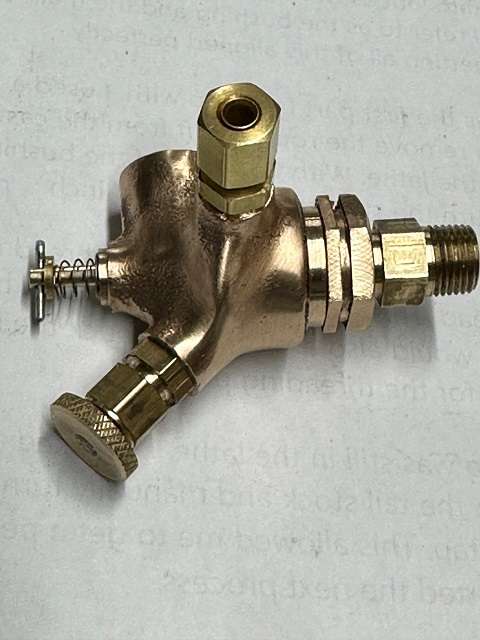
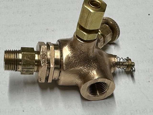
I test fitted the fuel needle valve and it all felt good.
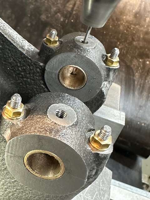
The vice was now rotated over to put the Air Intake Boss uppermost. This was faced off 0.656″ from the of the casting, hole centre location checked, 0.8227″, from end face of the casting and then drilled 8.5mm and tapped 1/8″ x 27 NPT. I had already made the inlet pipe so checked fit of the thread.
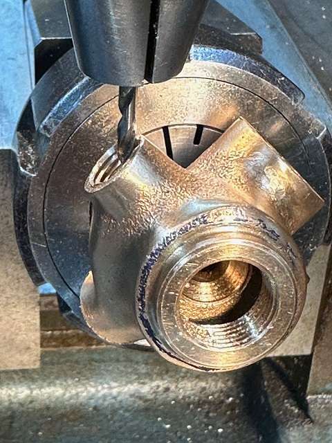
The collet block now turned through 90 degrees to put the Fuel Inlet Boss uppermost. Boss faced off 0.750″ from centre line. Centred on the boss using 7/16″ drill rod, this should be 0.5″ from end face of casting. Boss now drilled 6.3mm diameter for 0.310″ depth. This depth is critical so as not to break through into the holes in the cored area of the casting. Hole then tapped 1/16″ x 27 NPT and fit of fuel connector checked.
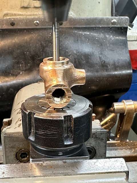
Casting now switched to smaller collet and held by the chucking spigot and the register at the top centered using co-axial dial indicator. Casting now drilled 3.1mm down through the centre and well into the chucking spigot. This hole then reamed to 1/8″
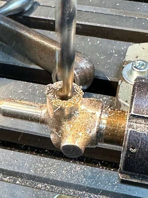
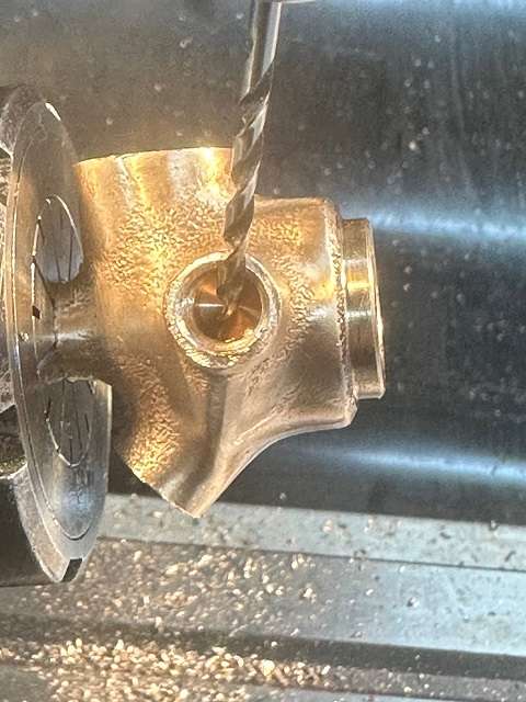
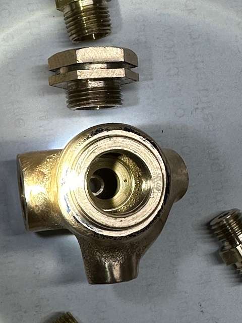
I now needed to cut the valve seat. This needed to have 45 degree face and be 0.447″ diameter. I went through all my countersinks and they were either too small or too bog to fit through the 1/2″ threaded top bore. I hunted through all my end mills and champher cutters but nothing suitable. Finally I found a brand new 10mm carbide spot drill. The cutting end was reduced compared to the shank, but the shank would just go down the bore.
Because the seat was deep down a hole I could not easily (even at all) see progress. In the end I wound the knee up until I could hear a cut being taken and then zeroised the knee DRO. Would knee down and checked cut, would it back up, took 10 thou cut, zeroised the DRO and wound the knee down again. Each time I checked to see where the fuel jet hole was.
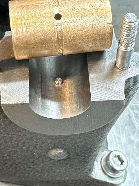
I continued like that until I had the fuel hole in the center of the seat and the seat to the maximum diameter of the cutter I was using. The hole can be seen in the picture above. In fact I went a bit too deep, about 6 thou, so used an end mill to remove the slight lip. A bit Heath Robinson but it worked.
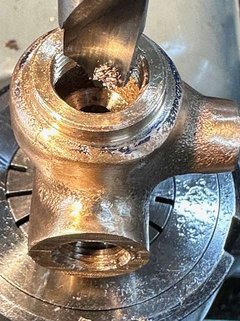
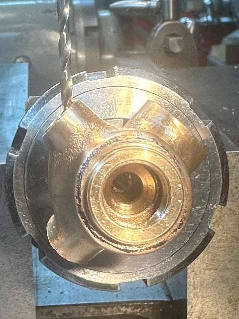
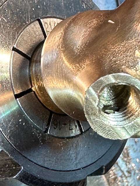
The next fun bit was the hole to link the fuel inlet boss and the needle valve boss. This needs to be 3/32″ diameter and must NOT break into the central area of the casting.. This required some careful lining up. The other issue is drilling into the side of a thread the drill will wander. The pictures show the story easier than describing it. I did use a tiny end mill to give me a flat spot to drill, followed by a long centre drill to put a pilot hole.
In theory I was meant to drill a return hole from the needle valve boss so the two joined up. I did not need to do this as I broke through into the base of the tapped hole. I reset the casting in the collet chuck and cleaned up the broken through area using a small end mill.
I cleaned up both threads using the appropriate taps and then fitted the needle valve and the fuel inlet union and checked that I could blow from one to another with the components fitted. All was okay.
The casting was then remounted on the mandrel, moved to the lathe and the chucking spigot removed. The various bosses then cleaned up with file and a trial assembly done.
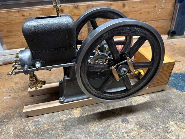
Getting there:
Need to make fuel pipe and fit fuel tank base. May well still peg the main bearings.
I have set the timing and I can see the inlet valve being sucked open and making a “sucking type” noise and can feel air being pushed out of exhaust. So looking hopeful.
When I first saw the Mixer plans I thought it was well beyond my abilities. 🙂
I am hoping the engine has enough compression. When the piston is at TDC I can fully depress the inlet valve without it touching the top of the piston. I have not checked how much clearance there is or should be. I guess if it is a bit too low then a thin shim between conrod and big end bearing would be the thing to do.
I posted this on MEM the other day and is what I’m currently working on to show the compression bounce. No ring fitted yet, no gaskets and valve springs not fitted just gravity closing them, fingers covering other holes. The squeak is air coming out past my finger
Do you use a high temperature paint on your models. I guess this is necessary for the cylinder head but what about the main body of the engine. Whose paints do you use. Looking at Dark Green (British Racing Green) for main castings and a Black for flywheels and head.
Decided I really ought to pin the main bearing bushes, so set the main casting back on jig plate at 25 degree angle. Put 1/2″ Drill blank through bearings and used this to centre up on bearing and then centered up between the main bearing bosses. I had some 5/64″ silver steel and planned to use this for the pins.
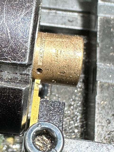
Removed the drill blank and moved to plus 1.219″ and drilled through the drilled oil feed hole through top of bush and then through bottom of bush and then 0.125″ into the casting. Repeated this at minus 1.219″.
Whilst the bushes were still fitted moved to a 3mm dia drill and just drilled through the top hole in each bush to aid with oil feed.
Removed the bushes and moved then over to the Myford into a collet chuck. I wanted to turn a groove to allow oil to spread around the bush. Used a 0.064″ parting tool. I was about to switch lathe on when remembered I did not want to remove any material adjacent to the lower pin location hole. Fitted lathe mandrel handle and turned spindle by hand but started cut about 0.625″ (1/16″) away from pin hole and stopped in similar position having gone almost full circle. Three passes was enough to get a small groove. Repeated for second bush.
My ER collets did not go small enough for the pin but I had 5/16″ 5C collet. Parted two pins off to calculated length of 0.185″. These were a little too long and I was worried they might mark the crank so removed a further 15thou.
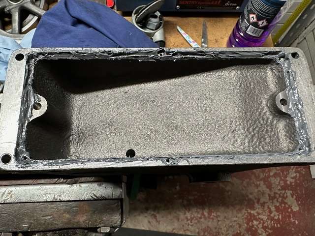
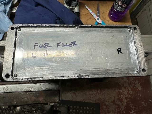
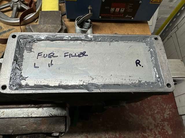
The main casting had already been drilled and tapped for 6 small screws to hold the stainless fuel tank base in place. A thin bead of JB Weld was run round the recess in the main casting and then the stainless panel screwed into place.
The excess JB Weld had squeezed above the panel and this was supplemented by a further bead of JB Weld and the fillet smoothed down into place.
Let’s hope it does not leak. Time will tell.
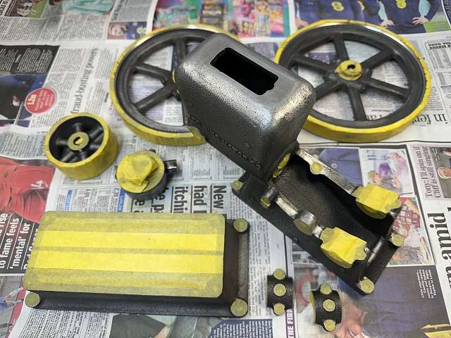
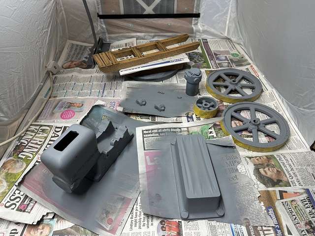
I was waiting for a small collapsible spray booth to be delivered and so used the time to make the final few nuts, bolts and studs required to hold the main casting, base casting and the wooden skids together. I also masked up the parts ready for painting.
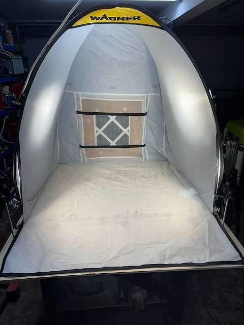
The collapsible spray booth arrived and then had the task of making an extraction system and some lighting for it. Some thin ply, a cheap bathroom extraction fan, some spare aluminium strip and sheet and a filter made up a working extraction system. It would suck a sheet of paper towards the filter, but it was only once I started to spray I could see how effective it actually was. I had 4 10W LED lamps brought cheaply from a local business that was closing down and these provided directional lighting.
Three coats of grey primer were applied to all components.
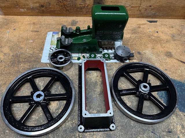
This was followed by 3 coats of top colour. Base casting, Flywheels, and Pulley were painted Gloss Black, Head with heat resistant matt black, and main casting with Rover Brooklands Green.
I had given the flywheels and pulley a good polish prior to masking up. I will give the paint 48 hours to fully harden and then clean up any overspray off the bare metal areas.
Then hope it all goes back together alright and the fuel tank holds fuel.
The fuel tank hold fuel without leaking. This was a bit of a worry but the JB Weld has done a good job.
Trying to get it to run is not going too well so far. Got the occasional chuff. Pretty certain cam timing and ignition timing ok. Fuel appears to be a bit of an issue. Initially I did not think I was getting any fuel through, so took the carb off and tried to suck to see if the valve would open. It did not appear to be lifting at all so I removed one coil off the spring. I could now suck and get the valve to open, if I blew instead there did not appear to be any air leakage down past the valve. Reassembled and tried again and am now getting leakage around the valve stem. When the inlet valve opens when piston on downstroke the carburettor valve can be seen to lift slightly and a suck can be heard through the carb inlet, although not particularly heavy suck. I guess if the engine actually ran then there would be no leakage as the fuel would be pulled into the engine. I also noticed that the fuel level in the tank was going down and realised that possibly too much fuel was now getting into engine now as it was leaking past the piston. Pulled the plug and it was wet.
What valve timing and ignition timing have others used. Also how far have you got the needle valve cracked open.
I know I am getting a spark from the buzz coil as I gave myself a huge belt by accident.
The plug I am using is a CM-6. It sparks when out of cylinder alright. Are there any similar plugs with a smaller hex nut on them I can only remove the plug by lowering the tail end of the exhaust push rod.
She certainly is looking good, Colin. I am sure you will get her running with a bit of fettling.
I have messed with a full sized carburettor something like that, a Schebler on a vintage 1920s Harley and that spring loaded inlet control valve can be a bear to get right. Most of the old timers threw those carbs away and put later model WW2 Harley carbs on them when they became available. Similar carb but without the spring loaded Mickey-Mouse leather flap valve as they were known. But they must have worked in their day so you should get there.