Building 1/4Scale Redwing Hit and Miss Engine
Building 1/4Scale Redwing Hit and Miss Engine
Home › Forums › I/C Engines › Building 1/4Scale Redwing Hit and Miss Engine
- This topic has 59 replies, 6 voices, and was last updated 6 May 2024 at 13:04 by
Hopper.
-
AuthorPosts
-
25 February 2023 at 21:18 #634990
Colin Heseltine
Participant@colinheseltine48622Wow Ian,
You are going along way quicker than me.
I still have to make a crank, do all of cylinder head, carb and exhaust, and machine the flywheels and governor. I have the material but not too sure how my silver soldering will go. I have not really done any in the past. The odd couple of bits have not turned out brilliant.
Couple of quick points: 1) I cannot see a locking screw for the timing shaft, 2) Have you used a locking screw on the crankshaft pulley, there is not one shown on my drawings.
Colin
26 February 2023 at 10:22 #635056Colin Heseltine
Participant@colinheseltine48622Ian,
A quick question. Looking at the plans am I correct in saying that the 0.250" brass ignition stud is pressed through the insulation collar and through the hole in the gear such that it just presses on the oilite bush and so completes the connection.
Thanks,
Colin
Edited By Colin Heseltine on 26/02/2023 10:40:35
26 February 2023 at 16:11 #635128Ian Bowers
Participant@ianbowers85137Hi Colin, I’ve spent a fair bit of time on it lately (maybe too much!) to answer your questions
I haven’t got round to drilling the timing shaft locking screw.
There is a locking screw on the crankshaft pulley
And yes the ignition stud goes all the way through to the oilte bush.
Just wondering what do you need to silver solder?
ian
26 February 2023 at 19:21 #635152Colin Heseltine
Participant@colinheseltine48622The ignition lever sleeve is silver soldered which I've done. But the crank will be built up rather than using casting. So the crank shafts and big end will be silver soldered into the webs. The ones I was given with the engine are both built up but just pinned and the shafts have all moved in the webs.
I still have to drill the timing shaft locking screw and it looks as though my plans have missed the crank pulley locking screw. I also found an error for the timing screw. The dimple for the locking bolt was shown to close to the bolt head.
I have done the insulation sleeve for the ignition stud and fitted that and the stud and also done the contact stud and its bushing. Need to make nuts and source spring.
Colin
2 March 2023 at 15:52 #635708Colin Heseltine
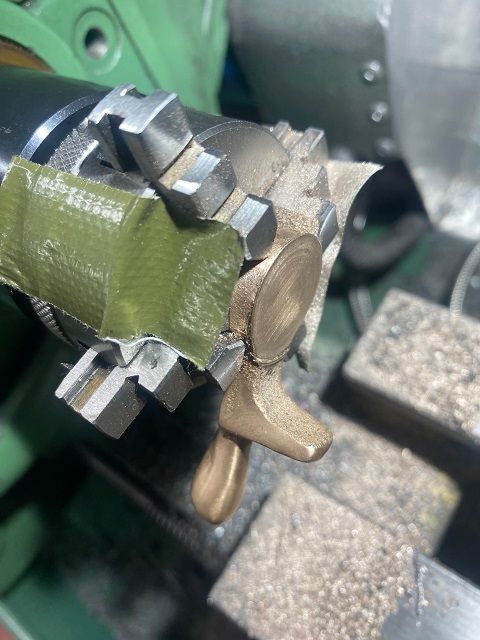
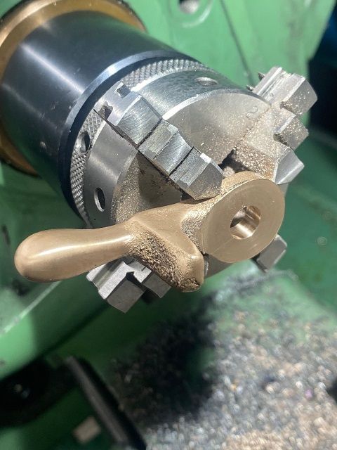
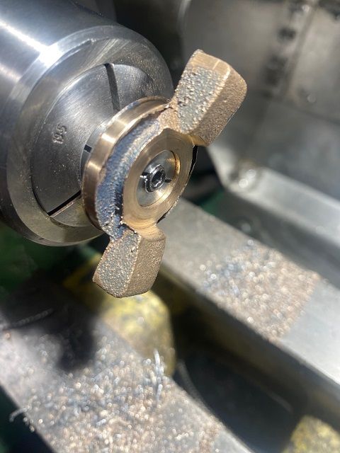
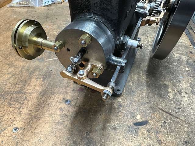
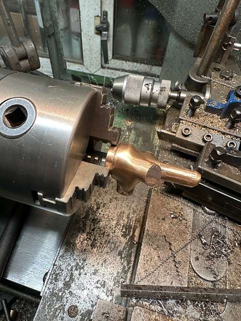
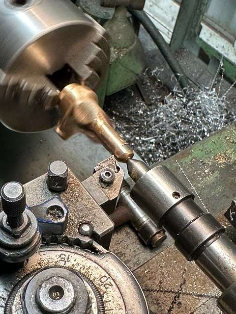
Participant@colinheseltine48622Moved onto Timing Lever. This is a small brass casting which is quite awkward to hold. First it was cleaned up with a file and sharp edges removed. Could not hold it my standard 3 or 4 jaw chucks used on the Myford, but I have a Myford spindle adaptor to be able to fit my M14 x1 threaded chucks from the Cowells lathe. The best option I found was the self centering 4 jaw but I still needed something to space it away from the chuck to leave face clear to machine. Found a suitable Joey block. I needed to leave this in place whilst facing so couple of pieces of tank tape to hold in place. This was faced on both sides to 0.188” thickness.
If anyone else does this can I suggest you face both sides to a larger diameter than I did. The rear face which mates against the casting was held clear by 15 thou or so and had to be filed and also the inside face needs taking right up to the bottom of the stick out for the timing stud. If you don’t do this you will find as I did that the cam will not rotate. Again, a bit more filing. I started drilling the casting with the Joey block in place and removed it just before the drill broke through. Hole then reamed.
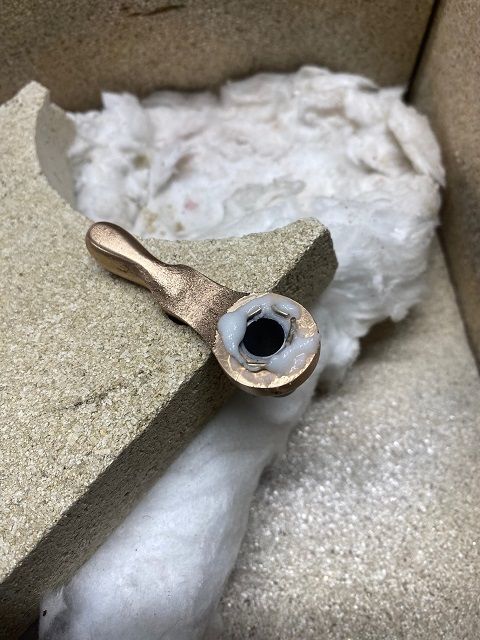
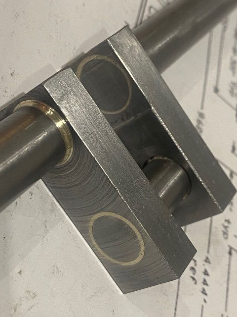
The thin steel sleeve is then silver soldered into the casting. Bit dubious about this but it appears to be held okay but need a bit more tidying than I had hoped.
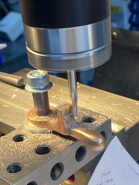
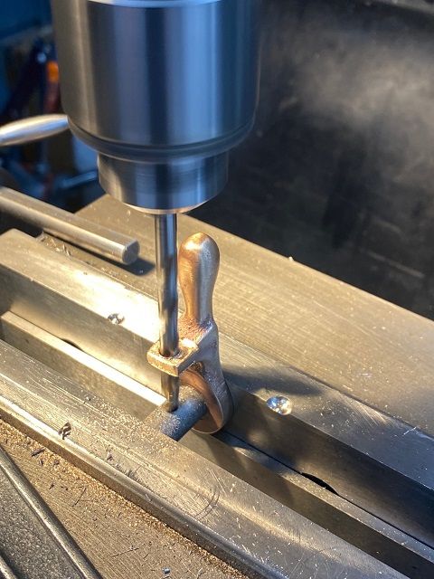
With the sleeve silver soldered in it was then possible to fix to a 3-2-1 block and clean up the top and sides of the boss on the casting through which the small insulation bush and contact stud are mounted.
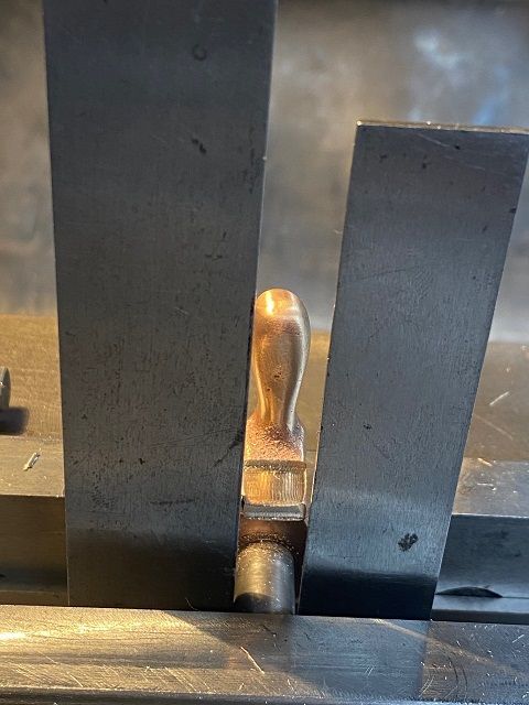
Aligned ready to drill and ream using two squares.
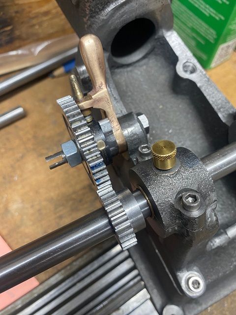
The oilite bush was shortened and then pressed into the timing gear. The insulation collar which is a firm press fit on the boss on the timing gear was next. I found I had some 1.004” diameter nylon/plastic bar and this was quickly made and the edge drilled for the ignition stud. Pressed this on the gear with the two holes aligned and then tapped the ignition stud into place. This passes through the collar and the boss on gear and is in contact with the oilite bush. I still had the soft jaws in the big lathe so returned gear to soft-chuck and then skimmed the proud edges of the ignition stud. The cam came next. I had to thin a piece of steel down to the required 0.188” t hen left it setup in the vice whilst marked out the cam.
The centre was then bored out. The steel then removed and excess cut off. Then used mill to bring down to within 1/16” of scribed line. Then used the die filer for its first proper job and shaped the cam. Back to the mill and centred on piece of bar then drilled and tapped 4-40 UNC for locking screw. This fits directly on the oilite bush.
Edited By Colin Heseltine on 02/03/2023 16:01:50
Edited By Colin Heseltine on 02/03/2023 16:05:22
Edited By Colin Heseltine on 02/03/2023 16:08:58
2 March 2023 at 15:54 #635709Colin Heseltine
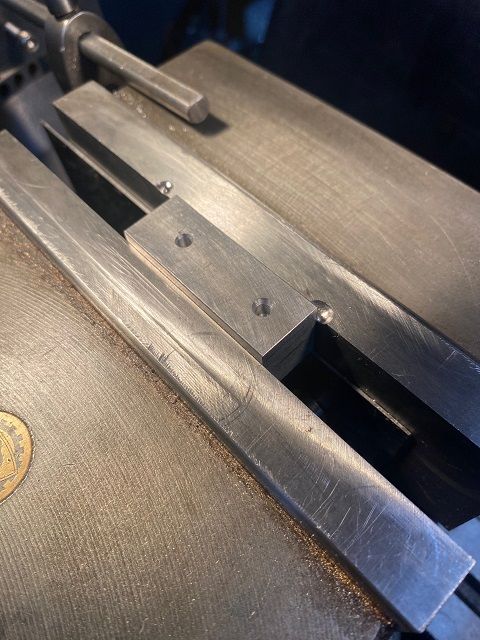
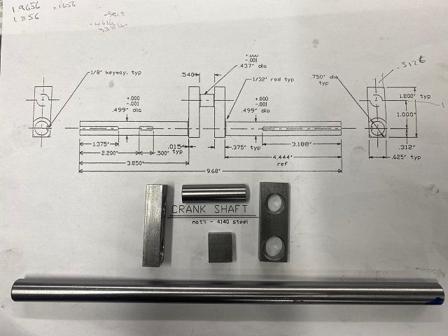
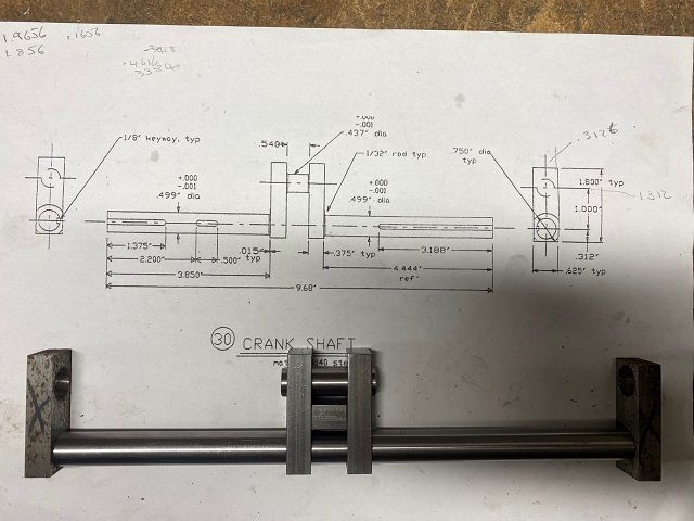
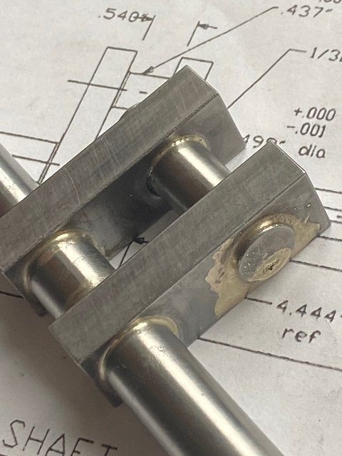
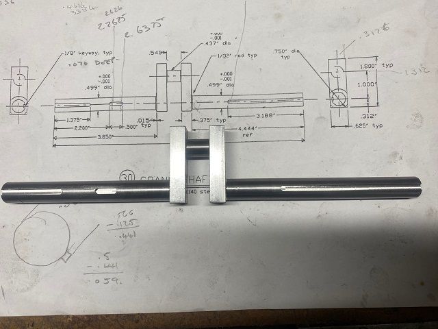
Participant@colinheseltine48622Decided I now had to bite the bullet an attempt to make the crankshaft. Two pieces of steel 0.625” x 0.375” by 2” long were cut and then super glued together. Into the mill and squared off and faced to length. Crank and big end centres marked with centre drill then drilled through in increasing sizes till just short of the required 7/16” and ½” diameters. Both holes reamed.
Crankshaft form PGMS cut to length and centred, big end cut around 0.125” over length. I also decided to make a spaced block from same material as the crank webs 0.540” thick. This used to ensure the two webs could be pressed against each other and keep correct spacing.
I had a spare pair of webs which had come with the engine so I reamed out the 1/”2 diameter hole and used these as supports for the outer ends of the crank shaft.
Now to the silver soldering. I first rang Graham Corry from Alyn Foundry and had a chat to him about silver soldering and then reviewed a video he had sent me a few pages back.
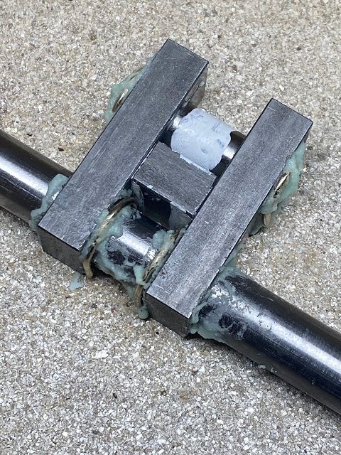
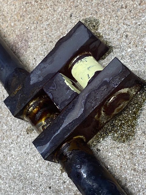
I set up the hearth on my wooden bench in the garage and put some heat bricks around the outside for extra protection. Cleaned all parts with acetone. Using HT5 flux I pre-fluxed the inside of the webs and slid them on the crank and big end. Slid them along to close to final position I then painted the made centre of big end with Tippex to prevent solder adhering here. Little more flux in all the countersink areas. Then cut 2 off 1” and 2 off 1.5” length of 1.5mm silver solder. These were then curled up into ‘C’ section shape and one put on each outer end of the big end and the larger one on the inside of each crank webs on the actual crankshaft. This was followed by bit more flux on each to hold in place.
Final check that the webs were in correct position and tight against the spacer, correct length of crank sticking out, ensuring the spare webs were on the ends of the shafts and all was ready.
Fitted the big burner to the torch and started by preheating the ends of the shaft and gradually moving towards the centre. I had turned the light off above me and could slowly see the colour changing. The flux was bubbling and changing so I now concentrated on the webs, big end and the inner section of the crank and suddenly it happened. The solder melted and did its stuff much to my amazement. I though I could see one slight gap so dabbed fluxed rod on it, looked okay so turned off heat and went and had lunch.
After lunch all was cool, looked reasonable so into jar of citric acid now for overnight and have proper look tomorrow.
2 March 2023 at 16:41 #635718 JasonBModerator@jasonb
All looks like the solder has all flowed to where it should and minimal amounts where it shouldn't so you won't have much to clean up
 2 March 2023 at 19:36 #635746
Colin Heseltine
Participant@colinheseltine48622Jason,
Thank you. I’m hoping it is all okay. Will leave in pickle overnight. Hopefully it will not need too much cleaning and isn’t warped. It’s my first proper attempt at silver soldering so reasonably pleased so far.
Colin3 March 2023 at 14:19 #635925Colin Heseltine
Participant@colinheseltine486224 March 2023 at 20:03 #636147Colin Heseltine
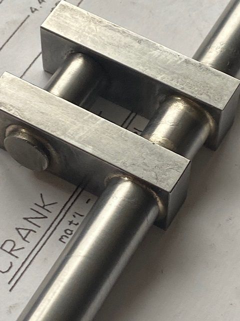
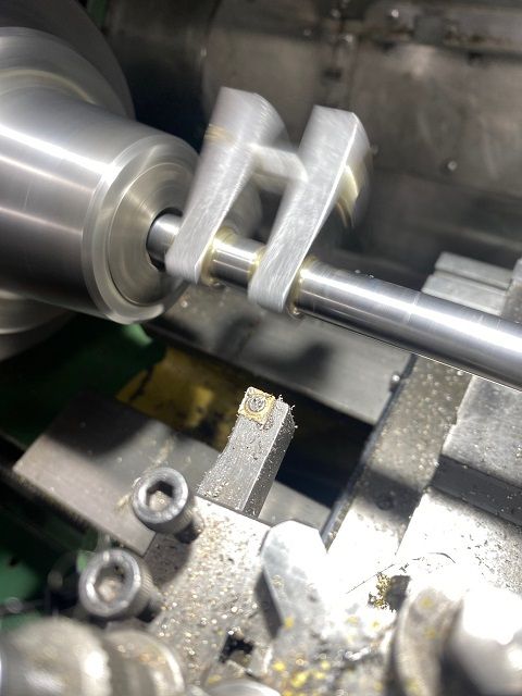
Participant@colinheseltine48622Into 5C collet chuck on Myford and the big end stick out faced flush to the webs.
Moved over to mill to remove the centre after first having hacksawed the majority out.
Final Result
Was going to start the keyways when the DRO display on mill appeared to self destruct. Need to talk to supplier on Monday.
9 March 2023 at 16:01 #636902Colin Heseltine
Participant@colinheseltine48622Very helpful supplier put me on to the technical man at Fagor. 10 minutes of his time and he had it fixed. Somehow I had set the system into Reference Mode.
Couple of key presses to exit and all okay.
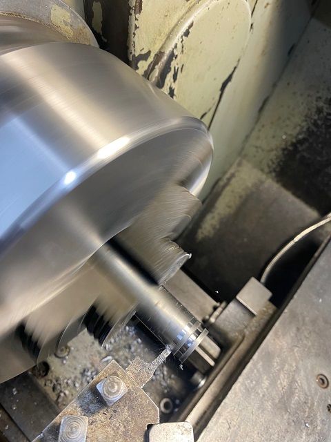
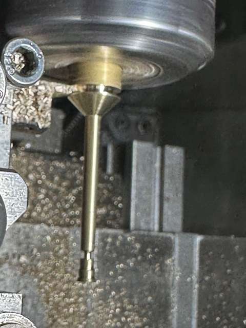
Whilst waiting to get mill DRO sorted jumped across to Colchester and turned the Governor Arm Shift Collar. I had correct size material in stock so just had to grind a 0.130” wide tool to cut the grooves. It actually worked quite well.
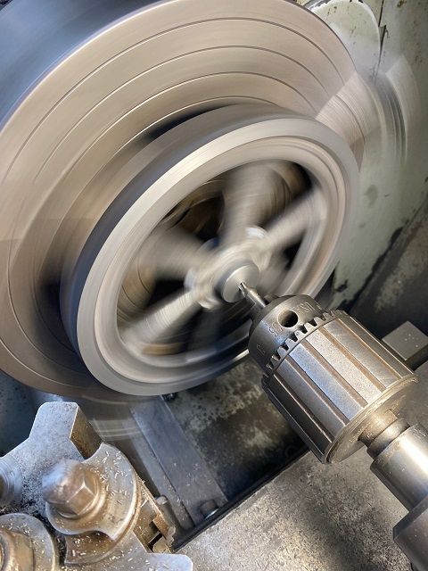
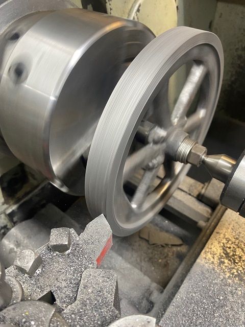
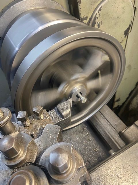
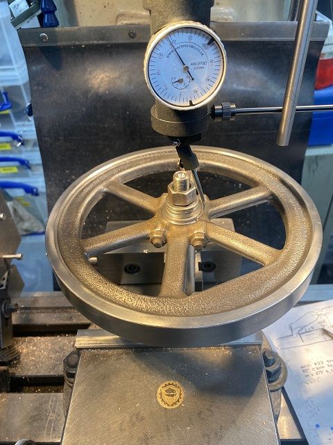
With the castings I had received one partially machines flywheel casting and one unmachined casting, both with many years of rusty brown colour on them. The machines one had the perimeter, sides, and bore completed. I needed to clean this up first to check on dimensions. It came up very nicely much to my surprise. The other casting looked quite rough around the perimeter and one boss was a little offset to say the least, but the spokes were very good with no movement of the two haves of the mould. Craned the 12” four jaw onto the lathe and proceeded to spend at least an hour trying to get the casting level and central.
Used carbide tipped tool to get underneath the skin and took the face down to dimension and then faced the boss. Boss then centred and drilled in steps to 0.4688”.
Could only get a very small boring tool in and very slowly bored out to 0.5”. Could now remove from the 4 jaw chuck and switch back to the 3 jaw. I had made a mandrel from a 0.875” piece of barstock and turned to 0.5” sand threaded the end ½” UNF and also centred the end. I hoped this would be solid enough for turning the perimeter. It ran true and I was able to take the perimeter down to approaching size but there was quite a dip on one edge. Before I went any further, I brought the side to dimension to reduce the area of the dip. Had I continued as I was I think the flywheel would not have tidied up until below size.
9 March 2023 at 16:02 #636903Colin Heseltine
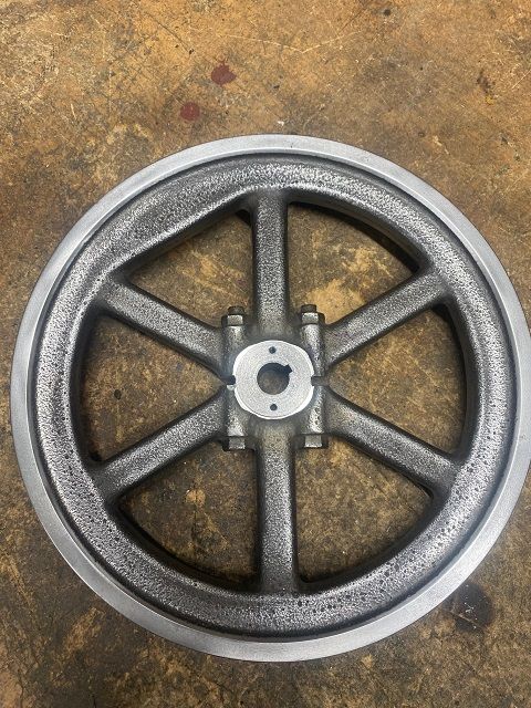
Participant@colinheseltine48622I could now compare the two flywheels and decide which to use on which side of the crank. The original one was to be on gear side and so this went onto a expanding mandrel to finish of the bosses to correct diameter and length. The other flywheel then mounted and bosses bought to size.
Both flywheels polished up well and the engine now looks a little more like it should.
16 March 2023 at 22:33 #637999Ian Bowers
Participant@ianbowers85137You look to be making good progress Colin, my drawing didn’t mention silver soldering the bush to the sleeve it just buts up against it.
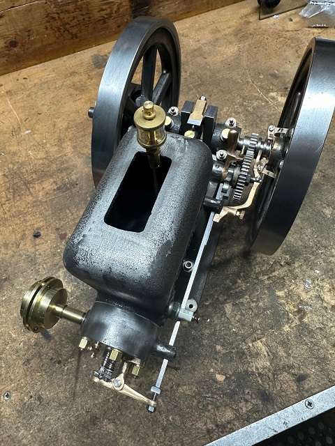
Any way now I have sparks ( see John Purdys Red wing post) I just thought I’d see if we had life. So I spashed a bit of petrol in the plug hole and after a few spins it fired up for a couple of turns. So I rigged a temporary fuel tank up and after a fair bit of adjustment to the mixture screw it fired up and ran ok but it was tricky setting the mixture.
As I was happy with the ignition timing I rechecked the valve timing and it was out so I set it as specified and pinned the cam. I think the cam had moved.
After a bit of trial and error I’ve found the best position for the mixture screw and it starts easily and runs very smoothly. I ran it without any water as I’m waiting for the oiler kit and even after ten minutes the cylinder was just warm .
I just need to sort out the correct nuts and bolts, finish the fuel line, tidy the wires then paint!17 March 2023 at 11:59 #638063Colin Heseltine
Participant@colinheseltine48622Ian,
Great to hear yours is a runner. It will be some time before I get that far. Currently doing slots in timing side flywheel, then need to broach keyways and drill tap for locking screws. Next step will be governor arm and latch out bars, followed by exhaust push rod.
Colin
20 March 2023 at 18:43 #638483Colin Heseltine
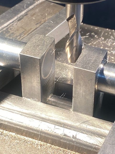
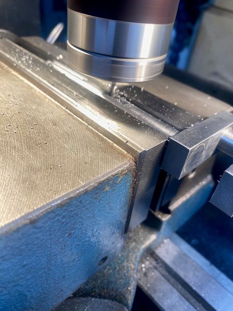
Participant@colinheseltine48622The keyways on the crank are 0.125” wide and 70 thou deep. Used a short 0.125” slot mill and ran it at around 2000rpm. Did three 20 thou deep cuts followed by 10 thou cut. Pleased with how this went.
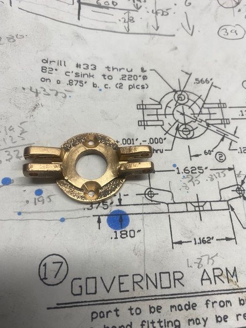
Governor Bracket was next on the list and this was a bit of an awkward thing to hold. After a bit of clean up I managed to get it held centrally in small 4 jaw chuck and then drilled it out to 0.5”. Then mounted it on a slit arbour to machine the rear face and main diameter. Turned it about face to bore the inside face and the bore between the ears for the governor shift collar and then the 15 degree angle on the back of the ears was next. At some point I realised I had a minor issue. The interrupted cut was moving the bracket along the split arbor. I had to stop and make a new slit arbor much shorted, a better fit and with a M6 grub screw in the centre to keep it out of the way of the boring tool.
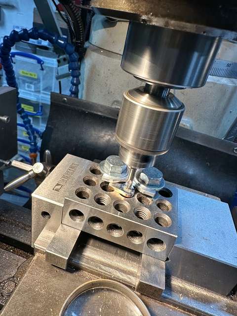
Decided to drill and ream the holes in the ears for the governor arms prior to milling the slot in the ears. Mounted on a 1-2-3 block and set it up square. I could not pick up on the bore diameter as I had a bolt through it so used the laser centre finder to pick up edges of the base and halved it. The holes drilled and reamed without any issues.
1-2-3 block then turned through 90 degrees to machine slots. The downside of using bolt and washers to hold brackets to 1-2-3 block was the inability to mill across in one go. Did each side at a time and was careful not to run the cutter into the steel washers. The other downside was that I could not drill the two 4-40 UNC clearance holes for the fixing screws. Removed from 1-2-3 block and sat it on parallel between pair of ‘V’ blocks and again used laser centre to pick up outside edges of the ears and get it square. Used 0.5” diameter drill blank to pick the center. Drilled both holes and then found 82 degree countersink to countersink the two holes. Because of the way the casting had been done the countersink covered two different heights of the base and so looks a bit unusual.
The brass casting needed a bit of cleaning up afterwards with riffler files.
20 March 2023 at 18:47 #638484Colin Heseltine
Participant@colinheseltine48622Moved onto the timing side flywheel and mounted this on large arbor and mounted it vertically between pair of ‘V’ blocks. Rotated flywheel to get the two slot positions along the X axis. Picked the centre up using coax centering device on flywheel boss.
Offset each side of the centre and drilled 0.125” hole as a guide for the slots. Then offset either side of centre on the ‘Y’ axis and drilled and tapped the 4-40 UNC mounting holes for the governor bracket. Flywheel then move to bench vice and the two slots cut with hacksaw and then filed to dimension.
Ideally I wanted a pair of grub screws in each flywheel to bear on the key, but there is just not enough room on the governor bracket side of the one flywheel, but on the second flywheel this was possible.
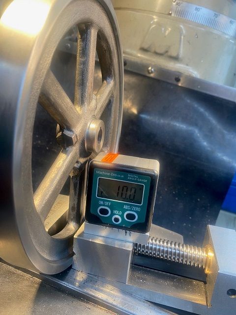
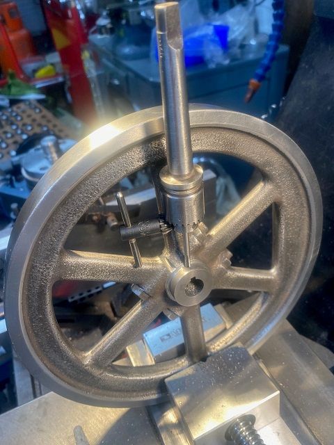
Flywheel was stood vertically in a vice and ensued that the keyway was uppermost and the flywheel spokes were aligned vertically. The smaller vice then put in jaws on main vice and magnetic angle gauge used to set the flywheel at 10 degree angle.
Used 0.5” drill blank and edge finder to find centre and set DRO to zero in both axis. There was no way to get a drill chuck in but I did have an ER11 long parallel arbor. This was used to hold 2.9mm drill. Double checked alignment by sighting drill in front of keyway and when happy moved to location of hole and drilled through casting.
Removed drill and replace the collet and inserted 6-32 UNC taper tap. Put spindle into neutral and turned spindle by hand to tap hole.
Then ran a bottom tap through hole using Jacobs No. 0 check to hold it.
Repeated this exercise for the three possible holes.
6 January 2024 at 16:48 #705158Colin Heseltine
Participant@colinheseltine48622Finally can bring this thread back to life. After a busy summer with major works in the garden, followed by eldest daughter wedding in Mid August, Week in France/Germany (in Caterham) mid Sept, Prague in mid Oct., first grand-daughter just after Christmas, I have only just managed to get back out into workshop.
I had done the flywheels and the Governor Bracket for it back in March, but the little castings for the Governor Arms and Latch Out bar had been staring at me all summer. I was not looking forward to all the tiny fettling and awkward work holding. I started on the Latch Out bar and gave this clean up with files and emery paper. I cannot find a picture of how I clamped this to drill the holes. The more I think about it, maybe I never took any because I was so ashamed of the somewhat precarious work holding methods I used.
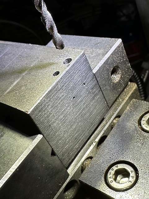
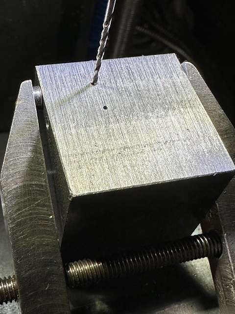
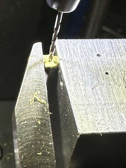
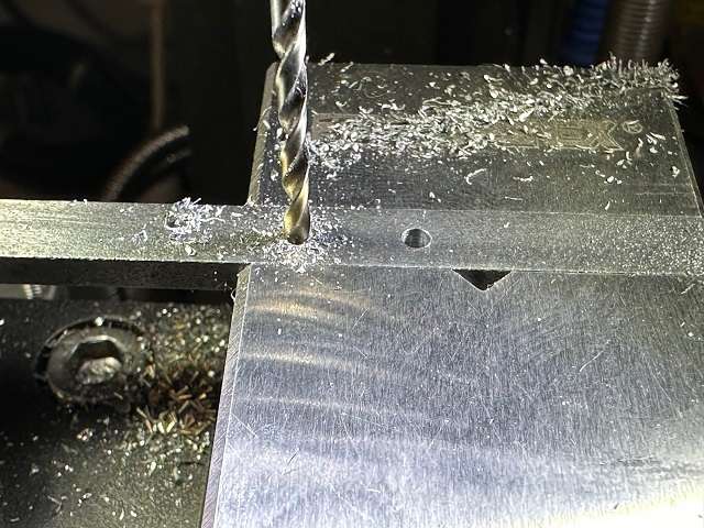
Decided to make the Latch Out Bar and the Governor Arm pins first of all. The plans just said steel and initially I tried piece of Silver Steel but the drive belt on the Cowells lathe could not cope so swapped to piece of BDMS. One pin at 0.093″ (3/32″) and two at 0.123″. I needed a jig in order to cross-drill these so set up block of steel in Cowells Mill and drilled the two cross-pin holes first. I had to use the nearest Metric size as did not have the correct Imperial drill. So 1.2mm instead of 3/64″ and 0.8mm instead of 1/32″. These were the smallest holes I have had to drill and so took my time and success without any breakages.

Then drilled the holes for the pins to locate in at 90 degrees to cross-hole. Removed block to blow out holes and then reset in position, fitted a pin and held in place with clamp and used DRO to locate the hole then drilled.


All went okay with the added bonus I found some 50 year old 1/32″ split pins which went in the holes.
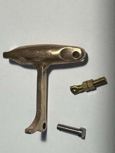
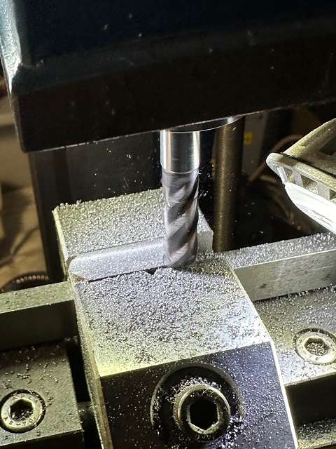
Then moved on to the Governor Arms. These are quite awkward bits to hold, one colleague suggested soft soldering a block onto the weight portion in order to be able to clamp it in vice. The casting was quite a bit thicker and needed to be thinned down quite a bit. In the end I fitted it to my small jig plate. It was placed on a sacrificial aluminum plate and up against two 6mm dia dowels located in the jig plate. It was then clamped down firmly with a small piece of aluminium between the brass body and the clamp. I ensured the arm was parallel to the jig base. This was then mounted in the vice on the Cowell Mil and a long series slot mill used to thin the sides down. There was some flex in the arm and a number of spring passes were taken until arm was parallel at 0.125″. This was then repeated for second arm.

The next task was to mark out for drilling. This was a fun task. It appeared that the casting was accurate enough that when laid on the surface table the arm was parallel to the surface table, so out with the Marking Ink and scribe lines all over to give the hole centre and the correct dimension of the arm in the other orientation, and also the locations for tensioner bolt and springs. Repeated for second arm. Arm then clamped down on 123 block with required hole location over a hole in the 123 block.

The 123 Block was too big for the Cowell Mill so migrated to the Bridgeport clone. Used the laser centre finder to pick up hole centre (forgot about my optical centre). Hole then drilled and reamed 0.125″ (1/8″). Block rotated in vice, whilst still aligned on center position and hole drilled for end of spring (1/16″).

Block rotated again and the location for the spring adjuster found and then drilled/reamed. This again was slightly precarious and needed and adjustable parallel to support the end of the bob weight whilst drilled/reamed and slight counterbore. Repeated again for second arm. No picture for this.
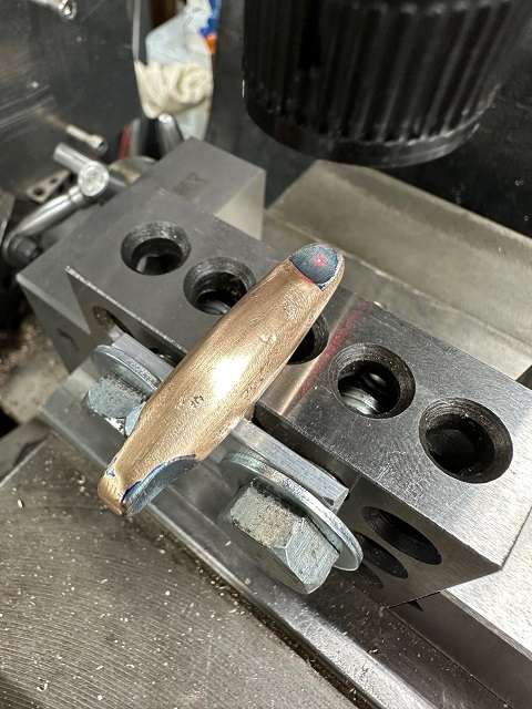
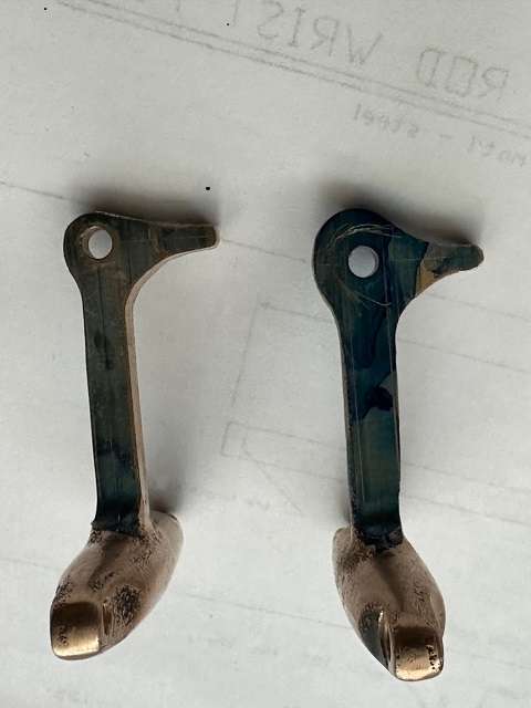
The pivot end of the Governor Arm now needs to be filed to shape. This is basically a case of filing, fitting to Governor Arm Bracket on the flywheel and testing the fit/operation. Eventually ended up with both arms operating the Shift Collar. Great I thought, so fitted to the crank and rotated. the flywheel. The pivot ends foul on the Latch Out bar. Then realised that the pivot ends needed to be radiused down to 0.125″ (1/8″). It would have been easier possibly to make a filing button to help with this. Instead I swung the arm suspended on a 1/8″ diameter bar resting on a pair on 123 blocks, blued up the arm and used height gauge to scribe the radius on both sides of the arm. Repeated for second arm and then spend happy hour or so filing to shape. The picture shows the arm with scribed lines on the right and the fully filed item on the left.

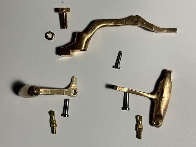
Next picture shows one arm with its mating parts.

Next picture shows both arms and Latch out Bar.

Next task will be to broach the keyway in the Governor Arm Bracket, the flywheel is done so will leave bracket on flywheel whilst being broached. These will be followed by Push Bar and it components and then the drive pulley.
Colin
PS Happy New Year to one and All
6 January 2024 at 20:08 #705238 Roderick JenkinsParticipant@roderickjenkins93242
Colin,
Nice work, thanks for sharing with us.
Rod
6 January 2024 at 20:25 #705244Colin Heseltine
Participant@colinheseltine48622Many Thanks Rod.
19 January 2024 at 17:12 #708495Colin Heseltine
Participant@colinheseltine48622I really cannot believe how long it took to make these fiddly little bits, it was at least 6 hours.
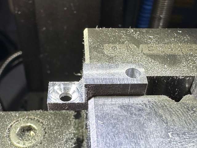
The Push Rod Guide plate is a small casting, this was cleaned up with file and then the two sides milled down to clean them up. Milled face down to 0.150″, Drilled two fixing holes whilst supported reasonably in the vise, then took down to final 0.12″ thickness.

Started with the Push Rod bar, seemed quite hard to drill, one hole 0.125″ (1/8″) for the pivot pin and the second hole for the fixing screw should have been 2.35mm for a 4-40 unc screw. I did not have a 2.35 so opted for a 2.3. Came to tap it and could not get more than 1 turn of the tap and could see the tap twisting.
Stopped and went to the pub. Whilst talking to my mate we both realised it was a length of key-steel we had bought from a business that was closing down (we in fact brought all their stock). Back home i put it in the kiln along with a couple of small castings and cooked it at 800 degrees Cent for a short while. Next day it was certainly easier to tap. Note to self – buy 2.65mm drill.
This was done on the small Cowells mill in the warmth of my office. Followed this by drilling the two 2.1mm holes for the 3-48 unc screws holding the Push Rod Plate.

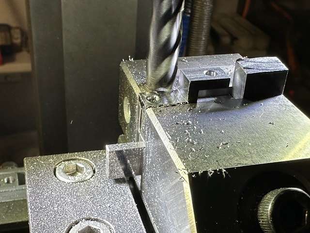
The Push Rod Keeper was cut from a 1.75″ x 1″ piece of .250″ thick plate. Sawed it down a little smaller the into vice on Cowells Mill. I had a 6mm Carbide end mill close by and used this to gradually whittle down to size. Then drilled 2.9mm (should have been no.32 drill but I do not have any) and countersunk for fixing screw. At the same time i drilled the hole for the pivot pin all the way through as I was not looking forward to holding the 0.1″ thick bracket whilst it was being drilled after I had milled down the opposite side.

I had great fun trying to find suitable height material to act as a parallel so as to keep the material well held in vice but still able to mill down to 0.1″ thick. Again very careful use of 6mm carbide end mill.

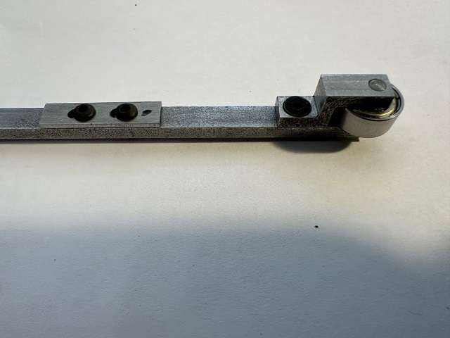
The Push Rod Keeper was fixed to the Push Rod Bar and clamped in the vise and 0.125″ (1/8″) reamer used to ensure holes were aligned with one another.
Because I was using a ball bearing race rather than a solid cam follower I had to deviate rom the plan for the Pivot pin. This was a simple turning job.
The final bit is the Push Rod Plate and this needed to be 0.048″ thick. Hunted high and low through stock to find suitable material and finally came across a flat grinding wheel cover which was 1.25mm. Hacksawed a piece out and by time I had polished the paint off it came out at the requisite 0.048″.
This was a difficult thing to hold in the vise. In the end used a set of Starret adjustable parallels with a piece of sacrificial brass on top of them. Drilled the two holes at the end of each slot and then used a 3/32″ slot mill to clean out the slot and open to the required 0.110″.

The various parts shown below.

And assembled.
 19 January 2024 at 18:19 #708502
 JasonBModerator@jasonb
Coming along, can’t be much left to do now?
19 January 2024 at 18:22 #708504Colin Heseltine
Participant@colinheseltine48622Cylinder Head, Exhaust, Pulley and Carburettor are the main bits left.
Colin
7 March 2024 at 20:22 #718809Colin Heseltine
Participant@colinheseltine48622Struggled a bit over last few weeks as wait for date to have biopsies done on prostate. Seem to run out of enthusiasm. That said I have managed to get head studs and nuts washers, main bearing cap nuts, pulley, exhaust all finished and today the cylinder head has been almost finished. Have couple threads to do and the exhaust and inlet ports to drill and tap.
But I need some help/advice/guidance. I have purchased spring wire to make the various springs on the engine (inlet, exhaust, governor, latch out bar and timing lever) but have never made compression or pull springs before.
Are the any words of wisdom on this topic, e.g similar to Jo’s treatise on making studs.
Many thanks
Colin
5 April 2024 at 18:17 #724408Colin Heseltine
Participant@colinheseltine48622Update to last post with a few photos.
Cylinder Head casting into four jaw chuck and centered up, centre boss turned to diameter and depth.


Head then moved over to Rotary Table on mill, centered up on the boss and then the DRO’s circle feature used to drill the head stud holes, the valve guides and the decompressor hole.

The guides were then reamed to size prior to cutting the valve seats. I had purchased a nice new Osborne cobalt 90 degree countersink cutter to do the valve seats. I used a piece of emery underneath the cutter to prevent any chatter and this worked perfectly.

When I purchased the casting I was given a pair of valves. The first one lapped in okay but the second had a good wobble. I went down to my mate with his Hardinge lathe and we used his expertese to get it straight.
The spent some time lapping the valves in. Various ways had been suggested to do this, but inthe end I opted for old fashioned wooden stick and sucker. Well not actually a sucker but used a hot glue gun to fix the wooden stick to the valve head. It worked reasonably but came unstuck every so often. Next time I do anything like this I will put a small screwdriver slot in top of valve. Based on all experience grinding valves in on cars I preferred to used a back and forward rotary movement and push down on the valve.

The head was then assembled on engine to see what it looked like.


In between the two photos above I changed the tappet adjustment screw to something looking a bit more appropriate, machined the pulley and the exhaust, but have no photos of these operations.
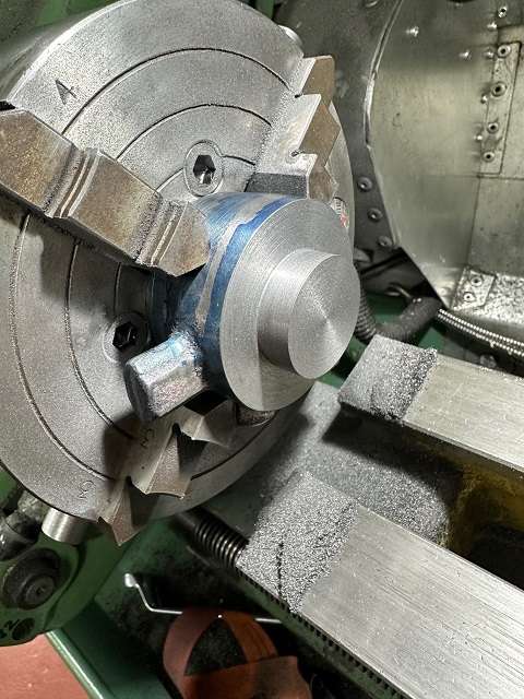
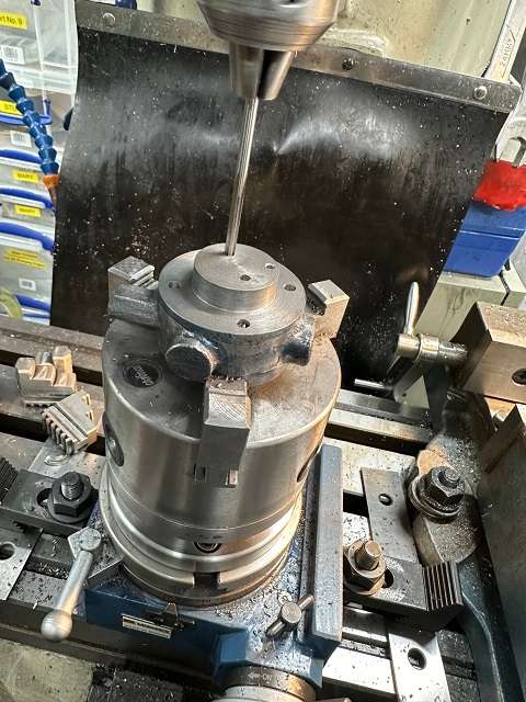
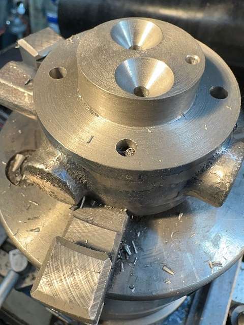
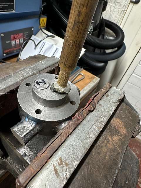
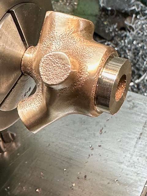
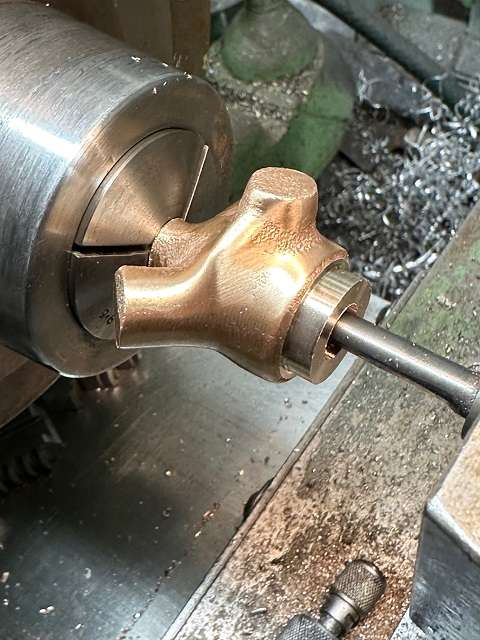
Now moved onto the fuel mixer. This is a Lunkenheimer mixer and I searched around for any build help I could find and eventually found some instructions for machining similar mixer but from different castings. This helped me get my machining in sequence.
I had been looking for suitable tap and die to do the thread in the top of the mixer. This should have been a 1/2″ x 24 UNF. I did not have one and could not find one at a suitable cost. My mate though he might have something suitable so too the casting with me and had a look through his taps and dies. Luckily he had a 1/2″ x 26 BSB tap and die, so we mounted the casting (which I had already cleaned up) in his Hardinge lathe. It was a delicate job to grip the casting by the 1/8″ deep rough shoulder on the top and get it centered and small center drilled in the end of the spigot at the other end.


We could now reverse the casting and machine the top end


 7 April 2024 at 18:34 #724594
Colin Heseltine
Participant@colinheseltine48622The top end was bored out to ensure hole square to casting and then drilled 11.5mm ready to be tapped 1/2″ x 26 BSB.
With this done I returned home to continue the job.
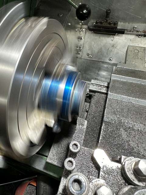
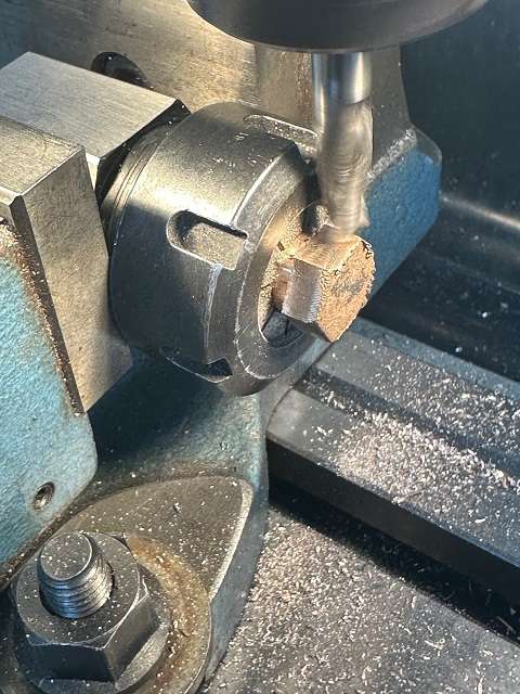
The Fuel Orifice Cap casting was first on the list. This was put in 3 jaw chuck and the end to be threaded turned down to 0.6″ diameter. This then set up in hexagon collet block and moved to mill and the six cast faces machined to give 11/16″ AF size.

Back to the lathe and turned down to 0.5″ diameter. A decorative groove put in the hex and a thread relief groove cut, faced to length and die used to put 1/2″ x 26 BSB thread on the end. This was then checked for fit using the previously threaded main casting.
Rather than continue with the main casting I decided to make the various fixings for the Mixer so these could be used to test holes/ threads when done on the main casting.
The fuel union was a standard purchased item with 1/16″ x 27 NPT thread. The Needle Valve fitting was a piece of 3/8″ brass hex with 5/16″ x 24 UNF threads each end and a 6-48 threaded hole through the centre. I had to deviate slightly here as I did not have a 6-48 tap or die so opted for 5BA.
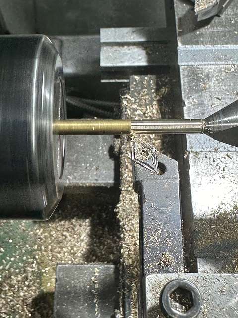
The valve was from piece of brass with 0.122″ stem and a 45 degree valve seat and a 0.430 diameter head. Chucked brass up in collet with short stick out and put a centre in the end, then extended out of chuck and supported end with half centre. Turned to the 0.122″diameter

and then cut the valve seat and parted off.

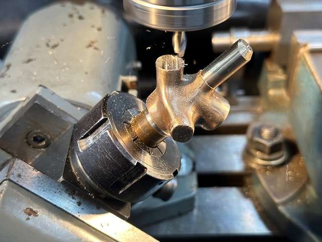
I made a 1/2″ x 26 BSB short brass mandrel to mount the main body casting on for machining and set this up in ER collet block. To machine the first part I needed this at 45 degrees, and I had intended to use Wixey electronic angle gauge, but I had been lent a nice Hauser Jig Borer vice with very good angular scale and accurate pin detents for useful angles. This was set to 45 degrees with the collet block fitted and the Needle Valve Boss set to be vertical.

This boss was faced off to give distance of 1.06″ to an imaginary point on the centre line of the casting where a hole through the needle valve boss would intersect. A further 0.187″ was then removed. Double checked that I was lined up on centre of the boss using a 7/16″ drill blank, then drilled 6.9mm 0.4375″ (7/16″) deep. Hole was then tapped 5/16″ x 24 UNF.
The plans specified that the fuel jet should be done with #65 drill (0.0350″). I do not possess any, but a 0.9mm drill is only 4/10 thou bigger, so that was used. I found my smallest R8 mounted Jacobs chuck, fitted drill in it and set mill to its fastest (4600rpm). The mill is a like a Bridgeport on steroids, which I felt was bit big for this little drill, and I did not want to break it in the hole of get it to suddenly pull in. I carefully pecked at the hole and gradually lowered the quill using the depth knobs to lower it a few thou at a time. All went well and it broke through into the hole in the centre of the casting without any issues.

-
AuthorPosts
- Please log in to reply to this topic. Registering is free and easy using the links on the menu at the top of this page.
Latest Replies
Home › Forums › I/C Engines › Topics
-
- Topic
- Voices
- Posts
- Last Post
-
-
Arc Euro Trade Ltd.
Started by:
Ketan Swali in: General Questions
- 4
- 4
-
21 July 2025 at 14:59
 Michael Gilligan
-
Diving in to ATC?
Started by:
Steve355 in: CNC machines, Home builds, Conversions, ELS, automation, software, etc tools
- 4
- 11
-
21 July 2025 at 14:55
 Martin Connelly
-
5 inch gauge Stirling single
Started by:
Michael Callaghan in: Locomotives
- 4
- 5
-
21 July 2025 at 14:51
Clive Brown 1
-
Hopeless…Alibre Ass
Started by:
Nigel Graham 2 in: CAD – Technical drawing & design
- 6
- 21
-
21 July 2025 at 14:40
blowlamp
-
Edward Thomas excessive wheel slip
Started by:
Ian R in: Locomotives
- 3
- 4
-
21 July 2025 at 14:11
Ian R
-
Hofmann Rollers
Started by:
Martin Kyte in: General Questions
- 11
- 18
-
21 July 2025 at 13:07
DC31k
-
Herbert B drill information?
Started by:
Andrew Tinsley in: Workshop Tools and Tooling
- 4
- 12
-
21 July 2025 at 12:45
 Michael Gilligan
-
What’s in the archive?
Started by:
Michael Callaghan in: General Questions
- 2
- 3
-
21 July 2025 at 12:36
Michael Callaghan
-
My vise isn’t at 90 degrees
Started by:
moonman in: Beginners questions
- 15
- 22
-
21 July 2025 at 11:47
 JasonB
-
Myford S7 VFD problem
1
2
Started by:
Glyn Davies in: Manual machine tools
- 21
- 38
-
21 July 2025 at 10:36
Glyn Davies
-
Model Engine running just off a naked flame
Started by:
 Blue Heeler
in: Stationary engines
- 6
- 18
-
21 July 2025 at 09:26
 JasonB
-
Model Engineer Magazine Collection
Started by:
mfengine1 in: Books
- 9
- 12
-
21 July 2025 at 09:22
Norman Blackburn 1
-
Panorama : Fighting Cyber Criminals
Started by:
 Michael Gilligan
in: The Tea Room
- 2
- 2
-
21 July 2025 at 09:20
Nigel Graham 2
-
Lidl castors
Started by:
 Michael Gilligan
in: The Tea Room
- 5
- 6
-
21 July 2025 at 07:30
larry phelan 1
-
Redwing Cylinder head
Started by:
Durhambuilder in: I/C Engines
- 3
- 4
-
21 July 2025 at 07:24
 David George 1
-
What Did You Do Today 2025
1
2
…
8
9
Started by:
 JasonB
in: The Tea Room
- 33
- 202
-
20 July 2025 at 21:39
Dalboy
-
Polishing compounds for stainless steel (mild abrasives))
Started by:
Simon Williams 3 in: Beginners questions
- 13
- 14
-
20 July 2025 at 20:02
 Russell Eberhardt
-
Bad design, or am I missing something?
Started by:
half whit in: Beginners questions
- 5
- 7
-
20 July 2025 at 19:16
 Julie Ann
-
Mistry dividing attachment
1
2
Started by:
Brian Merrifield in: Workshop Tools and Tooling
- 17
- 42
-
20 July 2025 at 18:43
 Tony Jeffree
-
Epoxy or acid etch primer
Started by:
Michael Callaghan in: Materials
- 1
- 1
-
20 July 2025 at 16:46
Michael Callaghan
-
Measuring a double Vee lathe bed Vee position
Started by:
Kim Garnett in: General Questions
- 11
- 22
-
20 July 2025 at 15:51
Kim Garnett
-
Please direct me to where I can find an engineer to do some bespoke work
Started by:
srb1 in: Beginners questions
- 6
- 10
-
20 July 2025 at 15:43
Craig Brown
-
Making Unimat DB/SL Steadies
Started by:
Andy Carlson in: Workshop Techniques
- 3
- 4
-
20 July 2025 at 15:35
Andy Carlson
-
Alternative to ARC
Started by:
petro1head in: General Questions
- 4
- 8
-
20 July 2025 at 13:31
 JasonB
-
Sat nag
1
2
Started by:
duncan webster 1 in: The Tea Room
- 24
- 50
-
20 July 2025 at 13:18
Nigel Graham 2
-
Arc Euro Trade Ltd.
-


