Building 1/4Scale Redwing Hit and Miss Engine
Building 1/4Scale Redwing Hit and Miss Engine
Home › Forums › I/C Engines › Building 1/4Scale Redwing Hit and Miss Engine
- This topic has 59 replies, 6 voices, and was last updated 6 May 2024 at 13:04 by
Hopper.
-
AuthorPosts
-
11 November 2022 at 21:36 #620704
Colin Heseltine
Participant@colinheseltine48622Late in 2020 or early 2021 I purchased a partial set of Redwing castings from the guy who used to import them into the UK and also build them. He had made a start on the main casting having skimmed the base, faced the cylinder head end, and machined the main bearing platforms. There were a couple of crankshafts, a used machined piston and a partially machined flywheel and partially machined carburettor.
At the time I had just finished a couple of Alyn Foundry engines and was working on a Stuart 10V. Covid and my Dad passing (just short of his 100th) and various other issues then got in the way and I have finally decided I need to get back in the workshop and try and do something useful. Although I have another 12 or so sets of castings on the waiting pile I decided to try and do the Redwing.
So this week I started to look at the main casting. Checking it on the marking out table, having removed a few burrs/bruises from the base showed the bore to be parallel to the base and the big end platforms at the correct 25 degrees. Checking the height of the bearing platforms I found that the main bearing centre would not be quite in the middle so I need to take a small skim of the platform to move it.
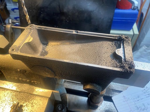
Started by mounting the casting upside down in the vice on previously machined area on top of water hopper. Several layers of thick card either side of the casting, clamp on top of the cylinder and a machinist jack under the free end of the casting. A bit of tapping and jiggling about and all was square.
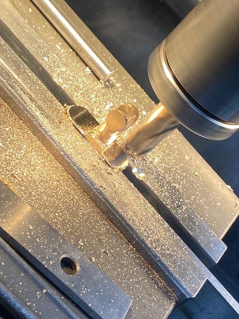
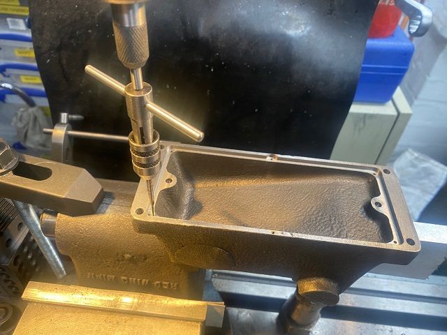
At this point in time all I wished to machine was the recess in the base for the steel forming the underside of the fuel tank, two dowel holes for lining casting up on a jig plate, 2-56UNC tapped holes for screws to hold the fuel tank base, main fixing holes for the casting and associated counterbore, and the tapped hole for the dummy cylinder water drain tap.
I had to borrow a 3/8" two flute slot mill as for some unknown reason I did not have one. Before starting machining I had done a drawing with all dimensions/moves calculated for the recess , main holes, tapped holes and dowels. I had also marked direction of table handles so as not to cock up. So pleased I have DRO on this mill.
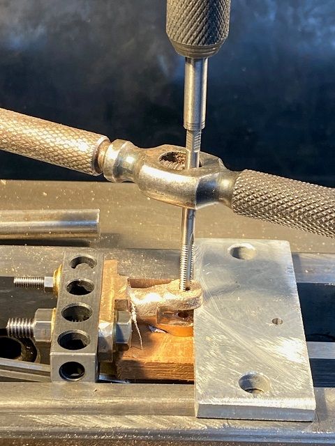
All went well, even the 2-56 tapping. I did not have the requisite 1.85mm tap so stayed with 1.8mm and went very slowly, 1/2 turn forward then half turn back.
I had ordered some .8mm stainless for the fuel tank base and carefully cut and shaped it and drilled holes. Next step is to modify a counterbore to use as reverse counterbore.
This will be a very steady and slow build. It is good to get back into the workshop and actually make something.
Colin
11 November 2022 at 21:36 #2642Colin Heseltine
Participant@colinheseltine4862212 November 2022 at 06:57 #620717 JasonBModerator@jasonb
Off to a good start, look forward to seeing some more progress.
24 November 2022 at 21:36 #622547Colin Heseltine
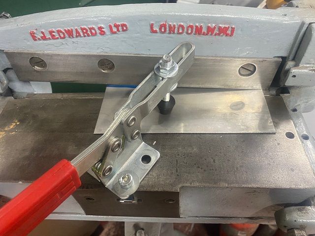
Participant@colinheseltine48622I mentioned earlier about the 0.8mm stainless steel sheet. mI was not sure how well this would cut and drill. I was able to use the small guillotine and it cut very cleanly and then radiused the corner using radius cutter in the flypress. The middle recesses were files out. Having had fun drilling stainless sheet with some work jobs in the pas I was a bit worried about drilling this material. I had planned to put small pilot/dimple in and then use punch in flypress, but did not have a small 2.3mm punch. I laid the sheet in the recess in the base as a support and used a 1.5mm cobalt drill at around 2500rpm. This went through easily. Then used 2.3mm Dormer drill in Proxxon mill at high speed to increase the holes size . Very happy with the result.
I had a piece of Tooling aluminum plate to use as a mounting jig for the engine. This was drilled and tapped to match the holes in the engine casting and also had the two reamed dowel holes put in. Because I cannot guarantee 100% that the locating dowels in the engine base are perfectly parallel to the cylinder bore I will mount the engine to the base, square it up using bar inserted into the cylinder bore and then machine the edges of the plate.
As I needed to remove the machine vice to machine the base casting and then machine the main casting I decided to machine the main bearing castings first. These had been partially machined and drilled when I purchased the castings. For some reason the holes had not been drilled at the requisite diameters. Mounted the first one in vice and located first hole using blank drill rod. Zero'd the DRO and then moved to second hole. This was correct distance away but fractionally offset. Drilled out to correct dimension 13/64" and then rest to first hole and repeated. Then used end-mill to counterbore the top. Slight mistake here in that I misread micrometer and took 25thou too much off. Not a huge problem but need to make the rest all the same depth. Skimmed top of cap for oiler location. Repeated this for second cap.
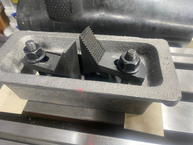
Removed the vice from mill and mounted the base casting upside down on two pieces of thin card. Clamped down and then squared it up. Did not want to use Verdict gauge so I used laser centering device. I could easily see as ran the laser down the edge of the casting.
I then went to do a double check with a Verdict gauge, which went well till I lifted the Verdict off the casting and power fed the table along the X axis. I had forgotten to remove the laser centre and ended up with a two piece centre as it met the hold down clamps. Doh!!!. How else to do a double check?? Used a standard rotating edge finder and checked each end of casting. I stopped testing when both ends were within 1.5 thou of each other. Used the edge finder to then center both Axis's.
Used carbide insert tipped facemill and cleaned up the bottom face.
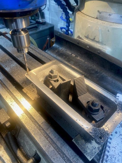
Drilled the four 13/64" holes for the feet, then turned the base over and reclamped in order to drill tap the mounting holes for main casting and also counterbore the holes just drilled in the feet.
 I used the edge finder again in same manner to centre the base up again. To ensure all was okay I put the 13/64" drill rod in the drill chuck, set the correct dimension in the DRO and picked the hole up perfectly. repeated for the other four holes. This proved my method of squaring the casting up had worked satisfactorily. Facmilled the surface to 2.313" height and then drilled the four holes 3.9mm and then tapped 10-24UNC.
Edited By Colin Heseltine on 24/11/2022 21:37:01
24 November 2022 at 21:37 #622548Colin Heseltine
Participant@colinheseltine4862224 November 2022 at 23:03 #622563Jeff Dayman
Participant@jeffdayman43397Looking great Colin! Nicely done.
4 December 2022 at 20:05 #623613Colin Heseltine
Participant@colinheseltine48622I needed to ensure the jig plate was square to the bore so mounted casting with 12" PGMS bar in the bore onto the jig plate (jig plate mounted on piece of 12mm MDF to protect the table) and eventually got it all square. Removed the casting and squared up the plate with large end mill.
Next exercise was to fit the adjustable angle plate to the table and get it square. Ran Verdict gauge back and forth along 'Y' axis to get this correct. Set the top of the angle plate horizontal and checked the top surface along 'Y' axis and found this not to be level. Then spent at least an hour getting jig plate level and square. In the end I needed a 6mm wide strip of paper along the rear edge of the jig pate parallel to the 'X' axis. This took a number of attempts to get correct.
When happy with this set the angle to 25 degrees.
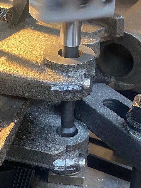
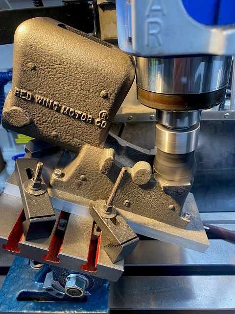
Used a 50mm six insert facemill to machine the main bearing faces. Because of the 25 degree angle care is needed to ensure the casting does not hit the quill. I had to remove the safety guard as this was in the way. Took three passes to remove 15 thou.
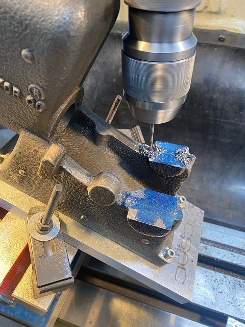
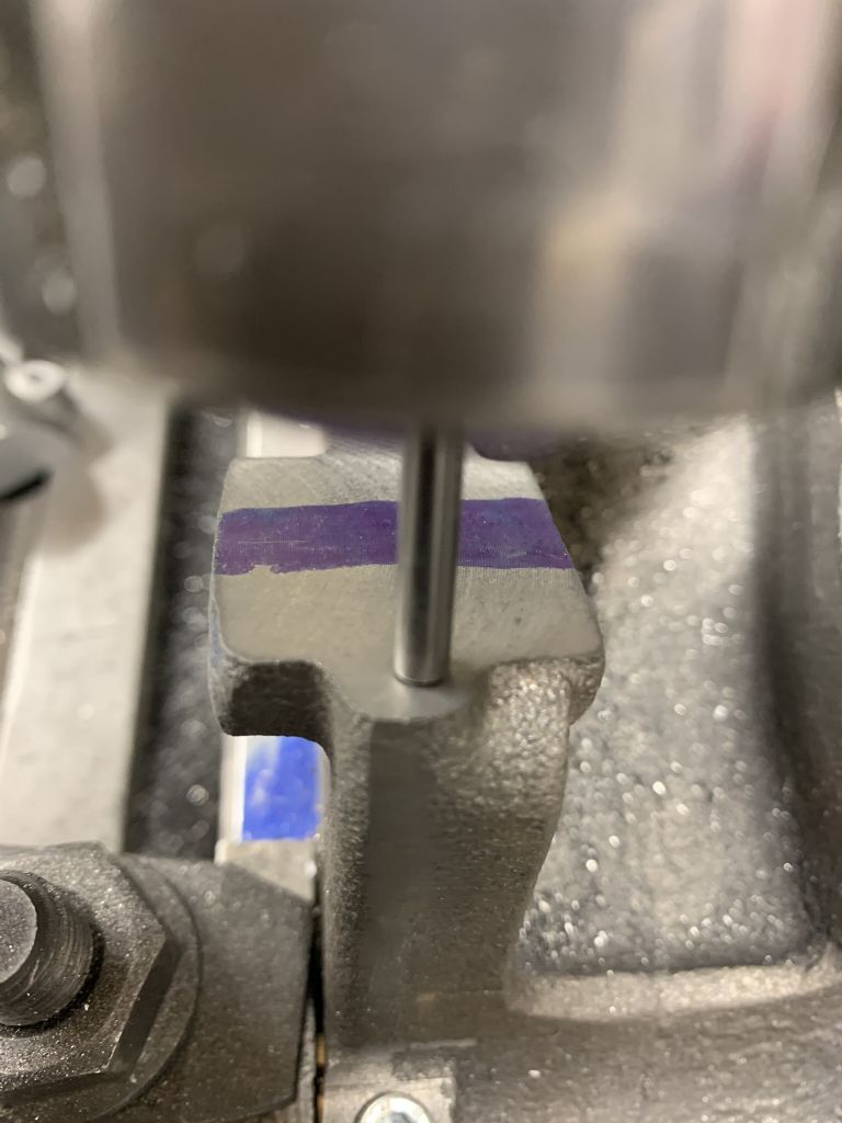
In order to check the positions for the main bearing caps I first blued up the bearing surface and then fitted one of my large (but relatively small diameter) drill chucks with a cobalt stub drill. I moved the requisite distance from the centre line (1.219"
 and very gently held the quill down so as to use the drill tip as a scriber and moved the 'X' axis so as to leave a scribed line. Repeated this for the second bearing.
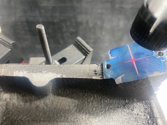
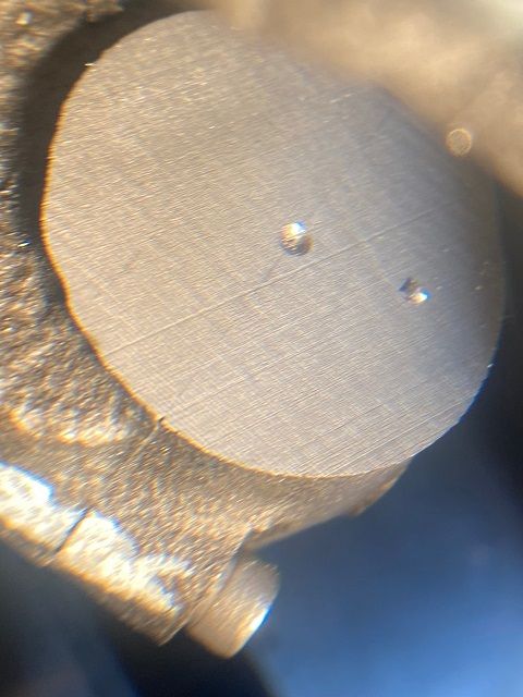
I could now try and work out the positions for the bearing caps. When I was thought I was correct I used a 4.3mm drill through the hole in the cap to mark location in the blue marking ink. Repeated this for both bearings. Then using a laser centre finder I played around until I was happy that both bearings looked good in relation to the bosses on the end of the casting, the diameter of the bosses on the side, and the location marks I had initially scribed on the casting. These can just be seen in the photo above.
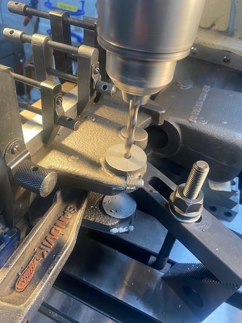
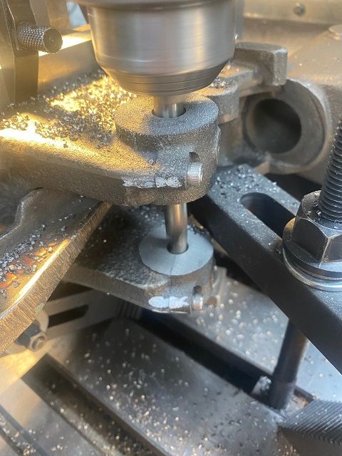
I zeroed the 'X' axis DRO on the bearing centre line and then drilled the 4 off 3.5mm holes 0.687" either side of the main bearing centre line.
The holes were drilled 0.5" deep and then tapped 8-32 UNC. The caps were then shuffled around to get the best looking fit.
Next step to face the sides of the bearings.
5 December 2022 at 21:19 #623756Colin Heseltine
Participant@colinheseltine48622Before putting the assembly back into the horizontal position I decided to do the main bearing oilers. Drilled into top of bearing caps going far enough that when bored out the drilled hole would be visible and then tapped 10-32 UNF for the oilers/greasers. Removed the rear cap and scribed a faint line on the bearing centre line to aid with location of fuel filler.
With this completed the assembly was rotated to the horizontal.
Picked the scribed line up with laser and moved 2.5 " back and 1" in to locate the filler. This did not quite locate in the casting correctly so amended position slightly. Drilled pilot and then ran 6.3mm drill through the casting into fresh air. Could not get the tap to start so milled a small 3/8" dia. counterbore to give level surface and then tapped hole 1/16" NPT.
Next up was the cylinder oiler. This needs a 3/8" recess milling in the top of the casting 3.250" from the rear of the casting. 3/8" endmill did this. Luckily my recent haul of carbide end-mills provided a long cutter which could be held in ER32 collet chuck and nestled into the recess and cut a flat on the cylinder top in the bottom of the water jacket.
This was followed by a long centre drill and then drilled 3/32" through to the bore. Amazingly I had a suitable long drill.
A 5.6mm drill then used to put 11/32" hole ready to be tapped 1/4-40 UNF. I found a long tap holder my father had made 20 plus years ago and carefully tapped hole with a bit of lubrication. Test fitted the drip oiler and all okay.
Now came to the bit I had been dreading, machining the gap between the main bearing boss and then reducing the mains down to 1" width. Before doing this I cleaned off the marking blue and lightly stoned the surface. Put a couple of spots of Loctite on the surface, but the caps set in place before I had the screws located. Tapped them free, cleaned them up, use a much tinier drop of Loctite and held the caps up until the screws were all started. The Loctite would ensure the caps did not move whilst being machined. Used a long 3/4" 4 flute end mill which meant I had to move .313" off the centre line to give the required 1.375".
I crept up to this very slowly taking around 15 thou of each side in turn. I used a set of Starrett sliding parallels to measure the gap and miked them whilst in place. Ended up at 1.3755".
Used same endmill do do the outside edges and in this case 2.065" on DRO gave me the 1" required width.
Fitted oilers and finished for the day.
Hopefully oilite bearings will turn up in next couple of days.
Edited By Colin Heseltine on 05/12/2022 21:25:06
28 December 2022 at 18:03 #626522Colin Heseltine
Participant@colinheseltine48622Wanted to complete all machining of main casting before Christmas as we were to have family stopping over.
I set my angle plate up on table and checked face was at 90 degrees to X axis and the face was vertical. It took a long time to work out how to fix the jig plate to the angle plate. In the end I had a thick parallel resting on table bed and two small 1-2-3 blocks on top of this. The edge of the jig plate rested on the two 1-2-3 blocks. Was then able to use clamps on the top edge of the jig plate onto the angle plate. Tapped down onto the 1-2-3 blocks and then could insert threaded rods in the gaps under the jig plate and through the slots in the angle plate. I just had room to clamp the lower edge with standard table clamps. It was solid.
Zeroed the DRO X-axis on the line between the jig plate and main casting and the Y-axis on the cylinder head face. Moved to what should be the bearing centre on the split line. Fitted laser centre and checked I was on the correct location. Perfectly aligned.
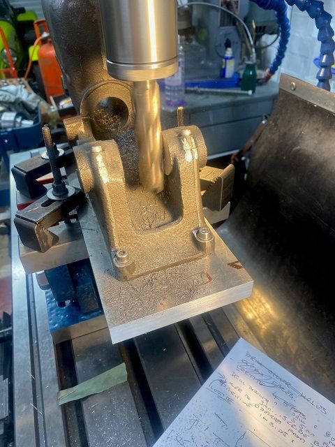
Whilst laser was still fitted did a sanity check on 1.25” bar fitted in the bore. This was parallel to Y-axis. Note in this picture the lower clamps can be seen
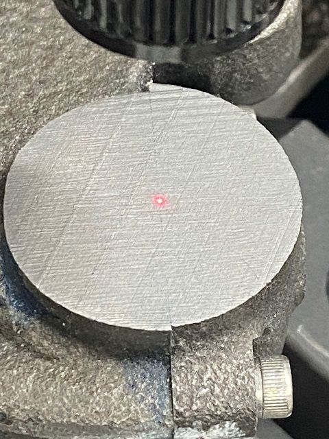
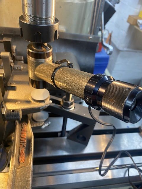
As a further check I fitted the optical centre and this picked up the bearing joint line perfectly. Now happy to start boring out the bearings.
28 December 2022 at 18:03 #626523Colin Heseltine
Participant@colinheseltine48622Spot drilled the centre and then worked up from ¼” drill to 3/8”.
At this point fitted long centre drill and spotted the middle of lower bearing. I drilled the upper bore at one size and then drilled the lower bore at the size below until had both bores up to 19/32”.
Prior to this I had spent some time at my mates house where we did some trial bores on a piece of cast iron to see which was best boring head/bar combination and whether or not to ream to final size. On testing my 5/8” reamer it cut 4 thou oversize, so that went out of the window. I have two boring/facing heads but had no boring bars small enough for either of them, an Arrand boring bar but the bar for this was bit too flexible. I ended up using the ubiquitous 50mm boring head sold by all the usual suppliers. I used the short carbide tipped bar for the upper bore.

On the top bore I went up in size very slowly and the last few thou had about 6 passes at each setting. Had clean piece of paper under the hole so I could see the material being removed. The Oilite bushes were nominally .625” but they were actually .6261.” I managed to get to dead size and with a firm push from my thumb the bearing went in the hole.
Extremely happy, just needed to repeat on the lower bearing.
I changed to the longer bar for the lower bore, but did not fully push it fully home. I just had enough length for the tip to finish cutting and partially exit the bore and still leave about 1/8" clearance between the boring head and casting. The auto stop on the down feed worked very well.
The longer bar was a little more flexible and I was doing 6 to 8 passes for each size adjustment. Eventually second bearing also pushed in.
With the bores done, moved onto the reamed hole for the timing gear. This went okay. When I came to the slot for the push rod, the boss on the casting did not appear to be quite where it should have been and the tapped screw holes would have been right on the edge of the casting. I elected to put them in the centre of the casting which put them out of place by 110thou. Looking at the length of the latch-out bar I do no think I will have a problem. Lets hope this is not “famous last words”.
I also drilled and tapped for the spark plug. This is exactly as per dimensions on drawings, but the boss on the casting is a tad high.
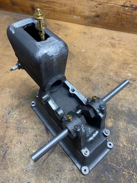
I then removed the casting from the jig plate and turned it over and remounted it, located and then drilled/tapped the 1/16” x 27 NPT hole for the fuel outlet union. Removed from jig plate, did some fettling around the bearing caps, and then assembled the bits so far.
The engine castings, as said before, had been started and I had been given a fabricated crankshaft. When fitted in the bearings and all done up, I could turn it but not very easily.
Did I have a problem with my boring or was it the crank. Only one way to find out, remove the crank and replace it with a ½” diameter length of straight bar.
This turned nicely. I will have an attempt to see if crank will straighten, otherwise will have to make a new one.
What to do next??
Colin
1 January 2023 at 22:56 #627134Ian Bowers
Participant@ianbowers851372 January 2023 at 17:16 #627239Colin Heseltine
Participant@colinheseltine48622Ian,
Hope you have fun building this engine. What size lathe and mill do you have? Whose castings are they. Having looked at the two used fabricated cranks I was given when bought the engine I will have to scrap them both and build a new crank. The ones I have were pressed in and pinned but the shafts are loose in the webs and the locking pins can be seen to move. Following discussions on Model Engine Builder I am going to fabricate again but will silver solder rather than pin.
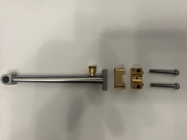
I see you have the one piece brass/bronze conrod. I do not have a casting for this so will use the brass bearing block and cut the rest out of a 1/2" thick steel block I also need to source a pulley. I have a couple of small steel flywheels so make look to see whether one of these will suffice.
While I wait for silver solder and HT5 flux I will have a little break as have a TIG welding job for a friend which will take several days. Solar panel mounts for his garage roof.
Colin
2 January 2023 at 22:06 #627274Ian Bowers
Participant@ianbowers85137Thanks Colin
It’s the PM Research kit and it’s my first model build but I do loads of stuff for trials bikes and agricultural engineering repairs. So I’ll be keeping an eye on your progress here for tips!
I’ve got a Beaver VRPB MILL and a Baileigh PL 1340 lathe (same as the Warco GH1340).
As for your crank would a tight press fit suffice like we use on motorcycles? Once together they can easily be aligned with a hammer. My kit had a ductile iron casting
Ian
16 January 2023 at 18:52 #629728Ian Bowers
Participant@ianbowers85137Hi,
Red Wing progress is good, base machined, recess for fuel tank base done and all holes drilled and tapped. I’ve made the base from 6mm aluminium and it fits nicely.
Cylinder bored and honed.
Main bearing caps done.
Ive just machined the main bearing surfaces on the body and am about to drill the holes, one side is about dead centre on the curve of the casting but the other is off centre , see photo below.
The question is do I drill it say 0.5mm to the left so the casting shapes line up better or stick to the original dimension?
Ian
16 January 2023 at 21:01 #629750Colin Heseltine
Participant@colinheseltine48622I guess the 1/2 mm move would look nicer. I fettled the castings once the mains were tightened down with a dremel so the castings matched. You may be able to do this. I had to play with the caps to get the best match prior to fettling.
U have come to a halt as have been doing a welding job for a colleague for last few days.
I have managed to get a new buzz coil off eBay. Will have a go at Conrod next.
24 January 2023 at 11:47 #630825Colin Heseltine
Participant@colinheseltine48622I was given two fabricated crankshafts with the engine and having looked at them both I think I will have to start afresh. In both cases the main shafts are slightly loose in the webs and can be seen to move as can the cross-drilled pins, supposedly locking the webs to the main shafts. Chucking one end in a collet chuck and running the lathe slowly the free end prescribes a circle.
Whilst waiting for silver solder and HT5 flux for the new crankshaft I decided to make the conrod. With some kits the conrod is a brass casting and in some cases if no casting it can be made from a single piece of steel or fabricated from three parts silver soldered together. I decided to follow the single piece of steel option.
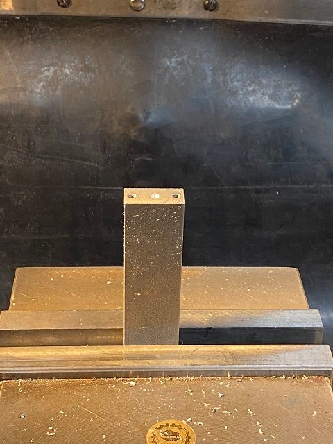
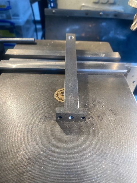
Started with a 5.125” x 1” x 0.5” piece of BMS. This was set up in the vice in a vertical position and edge finder used to locate centres in both X and Y axis’s. The top was squared off taking light cuts due to the large amount of stickout above the vice. The end was centred and whilst setup a 2.5mm hole was drilled down through the centre for distance of 0.75”. This is the feed hole for the oiler. Two holes were also drilled 3.5mm on 0.75” centres and these were tapped 8-32. These are for the two bolts holding the brass main bearing to the conrod.
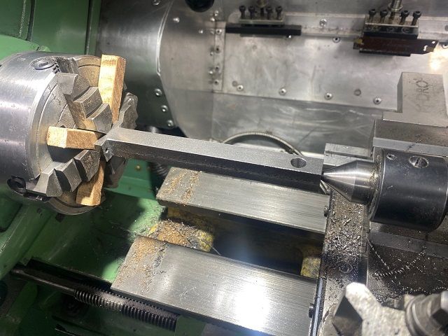
The piece of steel was then turned end to end and set up vertical again. Again the top was squared off taking light cuts due to the large amount of stickout above the vice. This end was then centred. The conrod blank was then moved over to Myford 7 lathe. The 4 jaw chuck was fitted and centres put in tailstock and headstock spindle. The conrod blank was held between centres and the jaws closed on the ends and sides. Jaws 1 and 2 then released ½ turn and blank removed (this will make setting up after the next step a bit easier).
Conrod blank moved back to mill and setup with 1” side resting on pair of parallels and the drilled and tapped end aligned with left hand end of vice. The DRO is set so that absolute zero for X axis is left hand end of vice and for Y axis is rear face of vice. The hole for the gudgeon pin (wrist pin) was drilled 7.7mm and then reamed 5/16” at a position on the centre line 4.638” from left hand end.
A quick tidy up of the corners and then turned through 90 degrees to rest on a parallel. 5/8” dia endmill then used to trim the material by 0.250”. The drilled and tapped end finish dimension is 0.20” so took end mill to 0.21” leaving rest to be turned off in the lathe.
When one side completed steel is turned over and the second side machined similarly.
24 January 2023 at 11:48 #630826Colin Heseltine
Participant@colinheseltine48622Conrod blank now looks a little more like a conrod.
It is now put back in the lathe. The big end fitting back between the previously set jaws. A wooden spider was made to hold it off the back of the chuck (centre in the spindle is no use now). Jaws tightened and DTI used to check conrod is centred.
Then spent several happy hours setting the topslide to give 3/8” per foot taper and then swapping lathe tools around to turn the taper. This was a right pain in the ass.
Finished off by turning the material away from the tailstock end to leave a ½” cube with the little end in its centre. The tapered shaft was then cleaned up with a file and polished.
Conrod then back to mill to put a 3/8” flat 0.7” from left hand end ready to drill 4.1mm and tap 10-32 UNF for the oiler, this was followed by a 0.062” oiler hole for the wrist pin. This was then countersunk slightly using a centre drill.
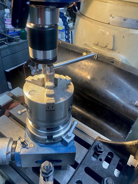
Last task was to round off the little end. Did not want to remove the vice or angle plate with the jig plate on it. There was not enough space for the 6” rotary table. I then remembered a Vertex 4” RT I had bought 10 plus years ago and never taken out of the box. This just fitted on a pair of parallels and clamped down diagonally across the table. Luckily the chuck mount off the 6” RT fitted on the 4” RT. Chuck mount centred under spindle and DRO zeroised. Found ¾” dia offcut from scrap bin, chucked it up in 3 jaw then drilled and tapped it M8. Chuck then moved to RT still with spigot in jaws. An M8 allen bolt with a short plain section used to hold conrod on the spigot. Then carefully radiused the end taking quite light cuts.
Rightly or wrongly I kept left hand lightly on unsupported end of conrod in case the bolt did not hold. Bolt held but the chuck wanted to unscrew and had to be tapped firmly back into place.
Quite pleased with end result. Now onto the big end bearing itself.
28 January 2023 at 19:32 #631211Colin Heseltine
Participant@colinheseltine48622Big End comes as a brass casting approx. 1.25” x1.25” x 0.75” which needs to be brought down to 1” x 1” x ½”. I decided to try the Joe Pieczynski (Joe Pie on Youtube) method of doing this. So into the vice on tall parallels and grip on the widest bit at the bottom of the casting draught. The top is then cleaned off till (took the various blemishes off) and then go round all four sides, one after the other as low as can get to top of the vice.
The piece is then turned over an put on parallels and the back face machines down to size. Then put in vice with large face on rear and one of the short machined edges resting on a single parallel at the rear face of the vice and then the size is cleaned up. This is repeated on other three sides, bringing down to size required.
Ended up with block to size as pictured.
Block set on parallels and centre finder used to find edges and then halved to get middle of piece for both X and Y. It was now easy to get the corner location for each flute and use ¼” diameter 2 flute endmill to produce this. Produced the radius at the bottom by switching to ¼” diameter ball end mill and went down each flute in turn.
This is where my brain and hand eye coordination completely vanished. L L. I grabbed the lever on the power feed to the knee and pulled the damn thing the wrong way. Hence the two ugly notches on rear top edge of my nice vice which can be seen in later picture. Good job the wife was out and did not hear my Anglo Saxon language.
Changed to a spot drill and marked location of two big end bolts and then run 11/16” drill through.
Turned the big end block through 90 degrees and set vertically on parallel on right hand edge of vice. I did not have a 1/16” fine tooth slitting saw and had to use a 1/32” medium tooth one. I had never tried slitting anything off like this before so ran at about 150rpm and wound the handles slowly. It cut well and very smoothly.
All edges now cleaned up and looked for two 11/16” pins to locate both halves together. Went through my fathers old stock and out of over 150 pins managed to find one. It was 1.5” long so it was quickly chopped in half. Big end put on narrow parallels and then drilled out in steps to 3/8”. Then bored out to .4375” ( 7/16" )
Edited By Colin Heseltine on 28/01/2023 19:34:35
Edited By Colin Heseltine on 28/01/2023 19:36:09
Edited By Colin Heseltine on 28/01/2023 19:36:58
28 January 2023 at 19:32 #631212Colin Heseltine
Participant@colinheseltine48622Found length of 5/16” rod and then over to Myford 7 and turned this down to 0.164 for length of .3125” and used 8-32 die to put thread on. Gradually slid rod out of collet chuck and turned to 0.168” for 0.875”. Then relieved last 1/16” of shaft and then put a 25thou deep .20” diameter step (to form washer under the head), then parted off .250” ( ¼" ) further along the bar (to machine as nut). Repeated to produce second bolt.
Decided that trying to see what I was doing milling the nut on the big mill was going to be a problem so I would retreat to the warm office and use the Cowells vertical mill. Fitted the indexing head which uses a gear for the indexing and fitted 5/16” 4 flute end mill. After 1/2 hour or so I had two ¼” AF bolt heads (4BA it appears).
I had forgotten to drill the oil hole in the base of the big end so quickly put in vice on the Cowells and drilled it out to 2.2mm dia.
I have left the bolt threads long in case I decide to fit a lock nut.
I cannot believe how long it took me to do the big end, it seemed like a full day.
Not sure what's next, crank or gears.
Colin
Edited By Colin Heseltine on 28/01/2023 19:37:39
Edited By Colin Heseltine on 28/01/2023 19:57:50
Edited By Colin Heseltine on 28/01/2023 19:58:44
18 February 2023 at 21:29 #634072Colin Heseltine
Participant@colinheseltine48622Still waiting for soft jaws for chuck to machine the gears to size and material for crank arrived late today.
So yesterday started on the rocker arm and rocker arm bracket. These are both small brass castings. Started with the arm and filed the sides down to 0.185" and as parallel as I could. Then able to just grip in vice with the two pads resting on the jaws. A very delicate skim was taken across the top face to bring the pads to the required 0.150" . Rocker arm then turned onto its side and the two pads rested on a freshly made MDF parallel. The machined top face was against the rear fixed jaw of the vice. Not enough space to get ordinary edge finder in so reverted to laser edge finder to pick up rear jaw and each end of the arm. Pivot point located and drilled and then reamed 0.125". Plan calls for 0.128" reamer but do not have this size. The casting then flipped onto its back, the center of the pad on the longer end of the arm found using a drill blank and then drilled and tapped 8-32UNC. No pictures of this procedure.
Now moved on to the rocker arm bracket. This calls for rocker pivot to be 0.780" up from the bottom edge and the bottom flange to be 0.125" thick. There was no way on earth to machine the base to this dimension by removing material from the bottom. A quick blast on the linisher to remove the casting sprue and clean the bottom up and then a quick check on surface plate. I could only afford to take the absolute minimum off to clean up. The casting was set upside down on couple of 4mm dia drills and bottom cleaned off. Ended up removing 15 thou to get flat face and even then the top was below drawing dimension by about 4 thou.
With bottom cleaned up the piece was turned its side and rested on a wide parallel and 12thou taken of the side, casting then flipped over and 12thou taken off the other side. With the bottom and sides cleaned up the casting was set the right way up and rested on parallel. Used my tallest parallel and then took the two flanges down to the required 0.125" thickness. Luckily the parallel I used just gave me about 6 thou clearance above the vice jaws. Back out of the vice and cleaned up the edges then back into the vice in same way but now on MDF parallel again. Picked up the sides of the boss with laser edge finder, half it to get centre then drilled the two fixing holes. The plans call for No. 1 and No. 30 drill for these holes but not having number drills elected for the next nearest size up.
Whilst set up I then cut the deep slot for the rocker using 3/16" ( 0.1875" )slot mill. The slot needed to be 0.190" and rather than go straight across I decided to plunge the end mill down to just short of the full depth and then repeat across the slot. Then offset the Y axis 1 thou in each direction to bring to width. I think in retrospect I would have been better using a smaller diameter slot mill as have slight witness marks from plunging in. Oh well, live and learn.
The downside to doing the slot first is the lack of support in the casting for first drilling the full way through and then tapping the one flange.
I slept overnight and thought about how to do this. In the end I was able to use a very small 1-2-3 block and fix the casting to it. The hole spacing only just worked. One M5 and one M3 bolt. Polished a piece of 5mmm thick aluminium to make a spacer for the gap, then used a combination of a piece of wood (so I could drill through it) and a Starrett adjustable parallel to support the casting. The aluminium strip also supported the casting. Checked it was all level by resting a parallel on top of the machined faces of the casting and using digital angle gauge. Edge finder used to locate back of 1-2-3 block and then set DRO to be zero in X axis for base of bracket. Used 11/32" drill blank to locate center of boss then drilled through 2.6mm to be able to tap 5-40 UNC.
Edited By Colin Heseltine on 18/02/2023 21:34:39
Edited By Colin Heseltine on 18/02/2023 21:58:24
18 February 2023 at 21:29 #634074Colin Heseltine
Participant@colinheseltine48622The hole tapped nice and cleanly. The problem was now how to line up casting when turned over to open up hole on other side. Having used vice stop I knew I was okay in X axis. Used 2.6mm drill blank in small drill chuck and gently moved Y axis until pin would enter the hole. Once happy with this I drilled it out to 0.125".
The casting was still a little long at each end so set up on parallel with end overhanging right hand end of vice. Put 2.6mm drill blank into the tapped hole and used laser centre find to locate middle of the pin. Could now mill off the extra material. Repeated this exercise for the opposite end. The over to die Filer to radius the ends, followed by a quick polish.
Again this was another job which seemed to take forever to do.
Edited By Colin Heseltine on 18/02/2023 21:35:31
24 February 2023 at 16:27 #634797Colin Heseltine
Participant@colinheseltine48622Went in to Rotagrip in Birmingham and collected the set of soft jaws for my new Elliot chuck and also picked up a set of small Imperial Broaches. I thought I had bought Metric broaches from them previously so happily collected the Imperial ones. Till I arrived home and found I already had an identical set.
I had bought the gears ready made from HPC but I knew they would want quite a bit of machining to bring them to correct thickness and have the correct bosses on them. What I started with can be seen below.
Fitted the jaws in chuck and found a suitable diameter bar on which to clamp the jaws to be able to bore them to hold the small gear. Bored 3/16” deep and a tight 1” diameter. Put gear in jaws and tapped down then did a quick sanity check with a drill blank in tailstock and checked it passed into the bore in gear. Faced off lot of material off down to 1/2” thick, then machined 0.750” OD boss on front which took the gears down to 1/4” . Drilled out to 15/32” then reamed to 1/2”.
Another steel bar to clamp the jaws on and then bored out to 2” dia for the camshaft gear. This gear came with a boss but this all needed to be machined off and the gear again bought to ½” thick.
Machined a 0.750” OD boss on front which took the gears down to 1/4” wide. Drilled out to 15/32” then reamed to 1/2”.
The timing gear required a 40thou deep recess in the back face of the gear and I really struggled with this, both to pick up the position and then to machine it. I made a trepanning tool of sorts with which I was able to start a groove but then tried various tools until I had a reasonable looking groove with sharp edges. I’m afraid positioning was carried out using a 6” rule.
Timing gear was then moved over to the mill and clamped in vice, ½” dia drill blank put through the bore and this was used to get centre of bore to drill and then ream to 0.156” for the ignition stud.
The crank gear was set up on the arbour press and the keyway broached. The keyway set comes with a single shim but this was not enough to get the required depth and had to make a further 20thou shim to get to correct depth.
24 February 2023 at 16:28 #634798Colin Heseltine
Participant@colinheseltine48622Now moved onto the Timing Gear Shaft. Did not have any hex bar so started with chuck of 5/8” diameter bar. Because I had around 2.5” sticking out of the chuck I had centred the bar and was using the half centre in the tailstock. All appeared well until I check the diameter and found 2 thou small in diameter at the tailstock end. Could not see why and cheated with a file to finish off to size and then polished shaft. I do not posses a grooving tool and used hacksaw blade in a parting tool to provide the thread relief before using 5/16”-24 unf die for the thread. Parted the bar off and took to the mill to put the hex head on the end using ER32 hex collet block.
This went well so changed to square collet block to put the slot and hole in the end. Set it all up and used 0.125” slot mill to put the slot in. Had done around four slow passes, when CRUNCH. Turned off mill and could not initially see what had happened. Then realised I did not have two little “D” shapes on end of the bar. The bar had rotated in collet chuck. Not surprising when I checked and found I had only done it up by hand, I had forgotten to clamp up.
Start all over again. But I though it might pay to check why the Myford was cutting tapered first. I know last year I had turned a test bar and all was good from the levelled point of view. So out with 2MT test bar and put this between spindle and tailstock centre. The tailstock appeared to be out by around 1.5 though offset to front of lathe so I corrected this and also checked/adjusted all gibs then started again. It still appeared to be cutting tapered when the tailstock was in use, pulled tailstock out and all would turn okay and parallel. I have absolutely no idea what to do about this or what the problem may be.
Any way second gear shaft produced in about half the time. As I write this I have just realised I have missed one tiny detail and that is a small dimple is required on the shaft.
25 February 2023 at 12:46 #634888Ian Bowers
Participant@ianbowers85137I made two of these as well Colin! I damaged the D shaped sides of the slot when I did the threading, the die caught and snapped one off!
25 February 2023 at 12:58 #634896 -
AuthorPosts
- Please log in to reply to this topic. Registering is free and easy using the links on the menu at the top of this page.
Latest Replies
Home › Forums › I/C Engines › Topics
-
- Topic
- Voices
- Posts
- Last Post
-
-
Myford S7 Taistock Adjustment
Started by:
 Harry Wilkes
in: General Questions
- 8
- 10
-
5 April 2025 at 01:19
 Steviegtr
-
How to wire up 3 phase motor and 3 phase converter?
Started by:
ell81 in: Beginners questions
- 7
- 8
-
4 April 2025 at 23:34
Emgee
-
Problem getting the right parameters on a VFD
Started by:
Robert Graham in: Electronics in the Workshop
- 1
- 1
-
4 April 2025 at 22:06
Robert Graham
-
What Did You Do Today 2025
1
2
3
4
Started by:
 JasonB
in: The Tea Room
- 23
- 78
-
4 April 2025 at 20:57
Nigel Graham 2
-
Powered hacksaw – blade lift for the return stroke
Started by:
 Sonic Escape
in: General Questions
- 8
- 17
-
4 April 2025 at 20:00
 Nicholas Farr
-
Damp proofing concrete floors
Started by:
Duff Machinist in: General Questions
- 13
- 13
-
4 April 2025 at 19:57
 Bazyle
-
New member old lathe
Started by:
t1krt in: Introduce Yourself – New members start here!
- 8
- 16
-
4 April 2025 at 19:52
t1krt
-
Elliott Omnimill Quill Clamp
Started by:
dangermouse in: Manual machine tools
- 3
- 3
-
4 April 2025 at 19:23
 Bazyle
-
Tangential tooling
1
2
Started by:
Keith Matheson in: Workshop Tools and Tooling
- 13
- 29
-
4 April 2025 at 18:14
Howard Lewis
-
Which lathes have drawbars in the headstock?
1
2
Started by:
ell81 in: Beginners questions
- 17
- 26
-
4 April 2025 at 18:04
Howard Lewis
-
Measuring increments on boring head
Started by:
Bill Phinn in: Workshop Techniques
- 14
- 17
-
4 April 2025 at 17:15
bernard towers
-
Stripped aluminum threads. Now what?
1
2
Started by:
brucemc777 in: Beginners questions
- 19
- 33
-
4 April 2025 at 16:34
old mart
-
gear cutting with the shaper
Started by:
jacques maurel in: Workshop Techniques
- 5
- 6
-
4 April 2025 at 15:15
Andrew Tinsley
-
Machinery Handbook
1
2
Started by:
Dalboy in: Books
- 30
- 37
-
4 April 2025 at 12:27
SillyOldDuffer
-
Flexispeed Meteor 2
Started by:
ferroequinologist in: Manual machine tools
- 11
- 18
-
4 April 2025 at 11:33
 Roderick Jenkins
-
Electric motor vibrations
Started by:
 Sonic Escape
in: General Questions
- 8
- 12
-
4 April 2025 at 07:38
 JasonB
-
Build Your Own Metal Working Shop From Scrap (7 book series)
Started by:
Dr_GMJN in: Books
- 6
- 7
-
4 April 2025 at 06:39
Pete
-
Scraping
Started by:
ryan.carter848 in: Books
- 7
- 10
-
4 April 2025 at 05:11
Pete
-
Ml10
Started by:
keel in: Beginners questions
- 5
- 7
-
3 April 2025 at 23:06
duncan webster 1
-
Warrington Model Engineering Developments
1
2
Started by:
colin wilkinson in: General Questions
- 14
- 41
-
3 April 2025 at 20:26
keel
-
Vice as Broaching Press
1
2
Started by:
James Hall 3 in: Beginners questions
- 16
- 37
-
3 April 2025 at 20:00
 JasonB
-
UK consumer protection laws?
Started by:
 Fulmen
in: General Questions
- 8
- 10
-
3 April 2025 at 19:07
 Fulmen
-
Marlco knurler wheels
Started by:
 Pete.
in: General Questions
- 6
- 15
-
3 April 2025 at 17:52
 Pete.
Pete.
-
Zig Zag Crimping Tool for eg Resistor/ Capacitor Leads
Started by:
 ma1colm
in: Workshop Tools and Tooling
- 4
- 6
-
3 April 2025 at 17:28
old mart
-
Safety Pickle for Steel
Started by:
aw1931 in: General Questions
- 3
- 5
-
3 April 2025 at 17:26
 Fulmen
-
Myford S7 Taistock Adjustment
-
Latest Issue
Newsletter Sign-up
Latest Replies
- Myford S7 Taistock Adjustment
- How to wire up 3 phase motor and 3 phase converter?
- Problem getting the right parameters on a VFD
- What Did You Do Today 2025
- Powered hacksaw – blade lift for the return stroke
- Damp proofing concrete floors
- New member old lathe
- Elliott Omnimill Quill Clamp
- Tangential tooling
- Which lathes have drawbars in the headstock?








 and very gently held the quill down so as to use the drill tip as a scriber and moved the 'X' axis so as to leave a scribed line. Repeated this for the second bearing.
