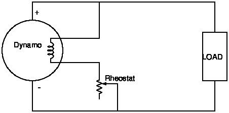
Simplest possible circuit is like this:

The wires allow amps to flow through a field winding inside the dynamo, much increasing the magnetic field and the machine's ability to generate power whilst also providing a way of controlling the output voltage to suit the load. The rheostat is a high-power resistor, usually wire-wound, and cranking the handle controls the strength of the magnetic field by adding more or less resistance to the circuit.
The circuit is very old-fashioned in that it requires an operator to manage the output. Typically only used on constant loads such as a set fair-ground lights. Automatic control circuits were soon added; these cope with varying loads and don't need an operator. Various ways of doing it: motorising the rheostat, using contactors to disconnect the winding when the volts went too high and reconnect it when they went too low. Most common I think was an arrangement of contactors that provided fine control by adding or removing fixed resistors from a selection. These days it's done electronically. Stabilising circuits are more complicated.
Various problems with rheostats:
- what value in ohms, and how many watts does it need to dissipate without going up in smoke?
- avoid burns and getting rid of the heat
- finding one – being grossly inefficient, rheostats are rarely used these days, and hard to buy
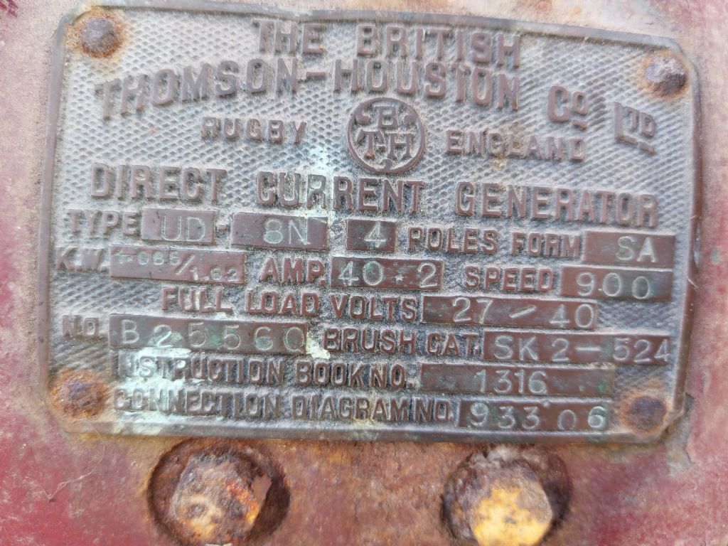
Guestimating wildly – I hope someone knows better – I'd start by assuming the field current to be about 10% of the dynamo's output, so:
- rheostat ohms = 40V/4A or 10ohms, and
- heat I²R = 4A * 4A * 10ohms = 160W.
Suggests a rheostat of, say, 0 to 40ohms and rated for 300 or 400 watts. Probably necessary to experiment – I don't know what the field current of a BTH Dynamo should be – when new, it would have been in the manual!
Dave
Howard Lewis.


