Bridgeport mill keeps c**pping out

Advert

Bridgeport mill keeps c**pping out

Home Forums Manual machine tools Bridgeport mill keeps c**pping out

Viewing 24 posts - 1 through 24 (of 24 total)
  • Author
    Posts
  • #738788
    Fulmen
    Participant
      @fulmen

      My mill (A&S built) died on me yesterday in the middle of a cut. Figured it was a blown fuse and called it a night, but today it started up just fine before dying again after a minute or so. The contactors won’t engage, but there is power if I push them manually. After a while it wakes up only to die again after a minute or less.

      I checked the transformer, all the windings seems to be at the proper voltage. I’ve checked the fuses and switches, everything seems fine. Are there any thermal/overcurrent protectors in the contactors?


      Advert
      #738808
      Mark Rand
      Participant
        @markrand96270

        Assuming that it’s the original 3 phase wiring, there probably are thermal overloads in there somewhere. You’d need to have a look in all the boxes to find where. You will still need to track down the source of the problem though.

        #738812
        Fulmen
        Participant
          @fulmen

          Yes, the wiring is original as far as I can tell. The motor runs on a VFD but that’s connected between panel and motor.

          #738813
          Clive Foster
          Participant
            @clivefoster55965

            +1 to Marks suggestion about thermal overloads.

            The old style automatic reset overloads are known to get crotchety in old age cutting things out randomly because they feel like it. I imagine many years of just sitting there doing nothing leads to build up of “stuff” and, perhaps, a loosening of the device that does the auto reset.

            Mine had a small spate of such happenings about a decade back. Cured “for now” by decent spray of switch cleaner lubricant and operating the auto manual selector a few times. Whether it was a real fix or whether the problem just randomly went away I know not.

            But if it ever happens again the old contactors and overloads are coming out and a new modern, DIN rail mount, set are going in. Truth to tell if I could have afforded the downtime to obtain new contractors and a DIN rail they would have been replaced there and then. But I needed the mill up and running to finish a paying job.

            Clive

            #738826
            Fulmen
            Participant
              @fulmen

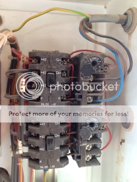
              The contactors are of this type:

              But I don’t see how they could be the cause since they all loose power. And I can’t find any thermal switches or other resettable components.

              #738834
              noel shelley
              Participant
                @noelshelley55608

                A loose or faulty connection in the holding circuit or coils ? The thermal overloads are in this circuit and often part of the contactor unit. Noel.

                #738838
                Clive Foster
                Participant
                  @clivefoster55965

                  Later style of contactor to mine. I think your originals have already been replaced.

                  The thermal overload units are on the right hand side of your picture, dial adjusts the currents setting.

                  The Bridgeport control circuit basically puts all the overloads in series so if any one pops out the machine stops. Sensible safety precaution really. But it does mean they all have to work.

                  Tightening up all the connections isn’t a bad idea. I have seen screw connectors on solid wire drift loose over the years. Presumably the copper wire flows a touch under long therm pressure.

                  Do you have the wiring diagram? If not I could send you a PDF of the wiring for a typical UK built one.

                  Clive

                  #738839
                  Fulmen
                  Participant
                    @fulmen

                    I can only see a current setting on the contactors, and these have not tripped. Besides, if one tripped they shouldn’t all loose power should they? I think I’ll focus on the holding circuit next, after giving the contactors a once-over with some switch cleaner.

                    #738843
                    SillyOldDuffer
                    Moderator
                      @sillyoldduffer
                      On Clive Foster Said:


                      The Bridgeport control circuit basically puts all the overloads in series so if any one pops out the machine stops. Sensible safety precaution really. But it does mean they all have to work.

                      Tightening up all the connections isn’t a bad idea. …

                      Without a circuit diagram I can only guess, but has the machine any safety interlocks?   Switches on doors, polycarbonate screens, covers, and those protecting against over-travel etc.   Last time my lathe misbehaved, it was because a safety switch had loosened just  enough to make intermittent content.  Had me confused for over an hour.

                      In addition to checking connections, it’s not unusual to find fatigue breaks inside the wiring of older equipment.   It occurs where vibration is able to waggle a wire in one spot, eventually causing an intermittent break. They can be difficult to find.   Try flexing the wires, especially any not firmly supported in a wiring loom, and have a good look at them wherever they pass through a bulkhead or bridge a large gap.

                      Fulmen seems to be taking the right general approach.  Isolate the fault by either working back from the motor until power disappears, or do the same by working forward from the power input.   That the motor runs when the contactor is worked manually suggests a problem in that area, and the locking circuit is my chief suspect!   Locking can be quite elaborate – a chain of switches all of which have to be right before the machine will run:  check everything.

                      In older equipment current and thermal trips are much the same technology – a bimetallic strip bends as it heats up, and if it gets hot enough, it releases a spring loaded contact.  After the bimetallic strip has cooled down, the contact can be reset.  Easily cleaned dirt often causes problems, but more seriously so does old age.   Over time the mechanicals wear out – insulating supports, springs, strip, contacts etc,  in which case the cure is a new contactor.

                      Dave


                      #738866
                      Clive Foster
                      Participant
                        @clivefoster55965
                        On Fulmen Said:

                        I can only see a current setting on the contactors, and these have not tripped. Besides, if one tripped they shouldn’t all loose power should they? I think I’ll focus on the holding circuit next, after giving the contactors a once-over with some switch cleaner.

                        The overload trip contacts are wired in series so if one trips out power to all contactors is broken so the machine stops.

                        Overload issues or contactor coil power supply from the transformer problems are about the only internal “everything stops” fault on a Bridgeport with standard wiring. Assuming the power supply is good and fuses properly screwed in.

                        Clive

                        #738887
                        Fulmen
                        Participant
                          @fulmen
                          On Clive Foster Said:
                          The overload trip contacts are wired in series so if one trips out power to all contactors is broken so the machine stops.
                          That’s very helpful, thank you.
                          #738926
                          Les Jones 1
                          Participant
                            @lesjones1

                            If the motor is fed by a VFD there should be no conractors between the VFD and the motor. Overcurrent protection should be provided by the VFD. (The VFD parameters should be set to suit the motor ratings.) Is the VFD supplied with single phase or three phase ? Even if you can’t provide a schematic can you at least provide a block diagram showing the path from the incoming supply to the motor.

                            Les.

                            #738927
                            Fulmen
                            Participant
                              @fulmen

                              The VFD is single phase, fed by the original contactor. This has worked for many years so that’s not the problem.


                              @SOD: No interrupts.

                              @ Clive: I’m pretty sure the contactors are original, I see no signs of fiddling or repairs.

                              #738930
                              Les Jones 1
                              Participant
                                @lesjones1

                                I suggest that you monitor the single phase input to the VFD to see if the fault is before or after the VFD. You could connect a small mains voltage lamp directly to the VFD input terminals.

                                Les

                                #738943
                                Fulmen
                                Participant
                                  @fulmen

                                  The fault is located before the VFD, this I know. Simply put all the contactors loose power, but they will deliver power if I push them manually.

                                  So a buggy overload sensor seems like a reasonable hypothesis. Not that any of them have tripped mechanically, I’ve checked the reset button multiple times. I’ll have a look later this week.

                                  Are these contactors serviceable?

                                  #738944
                                  Les Jones 1
                                  Participant
                                    @lesjones1

                                    I assume that the contactor coil is fed with a relativly low voltage from a winding on the tansformer. (Probably 25, 50 or 110 volts.) There will be a number of normaly closed contacts between one side of the transformer secondary and the contactot coil. These will be the stop button, the three contacts on the thermal overloads and any safety cutout switches. these cutout switches would be on machine guards and possibly on covers on electrical circuits. Check these contacts with your meter.

                                    Does the macine run if the start button is held pressed ? If it does then the fault will be the maintainer contact on the contactor. This is a normally open contact  on the contactor that is connected in parallel with the start button.

                                    A good clear picture of YOUR would be helpfull.

                                    Les.

                                    #738947
                                    duncan webster 1
                                    Participant
                                      @duncanwebster1

                                      I’ve had an mcb which had corroded contacts repeatedly tripping, the resistance of the contacts heated the bimetallic thing which made it trip, which made the contacts worse and so the heating was worse and so on on a vicious cycle. Fortunately I managed to find a replacement (now obsolete).

                                      #738962
                                      Fulmen
                                      Participant
                                        @fulmen
                                        On Les Jones 1 Said:


                                        Does the macine run if the start button is held pressed ?

                                        No, it’s completely dead. I’ll take some photos tomorrow.

                                        #739067
                                        Mark Rand
                                        Participant
                                          @markrand96270

                                          Couple of things:-

                                          1. Contactors downstream of the VFD haven’t been an issue for 20-30 years. They were an issue with GTO SCRs, but those are ’70s-early ’80s technology. Current VFDs use IGBTs, which do not suffer the problems.
                                          2. If you are feeding the single phase input VFD through the original 3 phase overload, with the current going through one phase’s connections, you’ll be using up to 1.73 times the expected 3 phase current (√3), so if that’s the case, you may get an over current trip if you haven’t adjusted the limits.
                                          #739079
                                          Fulmen
                                          Participant
                                            @fulmen

                                            I just realized this might be a punishment for this recent setup:


                                            Don’t worry, I didn’t turn the switch. But I’m running out of options, cutting it with an angle grinder will take forever.

                                            #739545
                                            Fulmen
                                            Participant
                                              @fulmen

                                              Had another try today. Gave the contactors a dash of switch cleaner and checked all the screw terminals I could see. I also gave the adjustment wheels a spin, but the result was the same. All contactor magnets loose power

                                              Here’s the panel:

                                              I think it’s safe to assume it’s original and unaltered.

                                              Bottom contactor is for the Erskine PSU and doesn’t seem to have any overload protection. Second is for the mill head, third for the optional slotting head and the top one is for the coolant pump. And yes, it has dawned on me that I should swap over to the slotting head circuit, I’ll try that next time (it seems to reset eventually).

                                              #739573
                                              Les Jones 1
                                              Participant
                                                @lesjones1

                                                Your picture does not show the wires comming out of the transformer connector so I can’t trace the wires from there. The botom sets of contacts on the contactors will be the maintainer contacts that hold the power to the contactor coils on.
                                                I SUSSPECT that the single fuse at the bottom right could be a fuse for the low voltage supply to the contactor coils. Make sure that is screwd in properly.
                                                Also the resolution of your picture is not good enough to read the lables on the wires.
                                                (The picture pixelates when enlarged.) You will have to trace the wiring to the contactor coils via interlock contacts and stop buttons.

                                                Les.

                                                #739586
                                                SillyOldDuffer
                                                Moderator
                                                  @sillyoldduffer
                                                  On Mark Rand Said:

                                                  Couple of things:-

                                                  1. Contactors downstream of the VFD haven’t been an issue for 20-30 years. They were an issue with GTO SCRs, but those are ’70s-early ’80s technology. Current VFDs use IGBTs, which do not suffer the problems.

                                                  When one of the phases between a VFD and the motor lifts off, by design or accident, there’s a high risk the winding will react to the pulse input like a car ignition or Tesla coil,  resulting in the coil outputting several tens of kilovolts.   Whilst the ordinary IGBTs in a modern VFD might well survive such an event,  voltage spikes of that size won’t do the motor any good!   Magnet wire insulation is likely to have tiny holes punched in it.  Might cause instant magic smoke, more likely each incident will cause the winding to slowly degrade due to shorted turns etc.   Older motors are more vulnerable than new ones.   If a contactor is in circuit that too will get the kilovolt treatment, also likely to damage it in some way.

                                                  Probably other risks too: mechanically damaging the motor, say by the voltage spike earthing through and pitting a bearing surface; or zapping the operator by jumping into the low voltage system.

                                                  I’ve read manuals that explicitly said the VFD must always be directly wired to the motor, and a few that don’t.   But the manuals that are silent on the need for fixed direct connection all have circuit diagrams showing only that, and don’t discuss alternatives.   An optimist might see that silence as confirmation that switching phases after the VFD is OK;  I don’t, perhaps because I’m a cowardly lion!

                                                  Also possible that I’m out of date!   Mark highlights the massive improvement in IGBTs, and it’s true the current generation of these devices has impressive high-voltage and high-power performance.   It’s also possible that the VFD circuitry that exploits IGBTs has improved whilst I was dozing such that a loose phase is detected and automatically managed without risk to the electronics, motor or operator.     Easy to forget how quickly electronic engineering develops compared with mechanical, and how rapidly features that cost a fortune a few years ago are quietly bundled into the economy model, at no extra cost.   Unwise though I think to assume that such improvements apply to all VFDs on the market and that amateur electricians can therefore do what they like without consequences.   That a circuit apparently works does not mean all is well: any damage being done may take months to appear.   A simple example is what happens when the capacitor across the centrifugal switch in a single-phase motor loses capacity.   Although the motor apparently runs normally, the contacts are wearing rapidly due to sparking, and one day the motor won’t start.   Replacing the capacitor is cheap and easy, but fixing a spark eroded centrifugal switch could be nasty, perhaps to the point of having to replace the motor.

                                                  Dave

                                                  #739623
                                                  Fulmen
                                                  Participant
                                                    @fulmen

                                                    Well, it’s working again.

                                                    I suspect it was the switch cleaner that needed some time to soak in, after some fiddling today it started behaving like it should again. It was the overload protector for the motor that wouldn’t reset properly (I was running some fairly heavy cuts). It’s also possible it’s become a bit more sensitive over the years, if it happens again I’ll probably bypass it and let the VFD limit the maximum current.

                                                    Thanks for all the help and support guys.

                                                  Viewing 24 posts - 1 through 24 (of 24 total)
                                                  • Please log in to reply to this topic. Registering is free and easy using the links on the menu at the top of this page.

                                                  Advert

                                                  Latest Replies

                                                  Home Forums Manual machine tools Topics

                                                  Viewing 25 topics - 1 through 25 (of 25 total)
                                                  Viewing 25 topics - 1 through 25 (of 25 total)

                                                  View full reply list.

                                                  Advert