Brian’s 1″ Minnie Traction Engine

Advert

Brian’s 1″ Minnie Traction Engine

Home Forums Traction engines Brian’s 1″ Minnie Traction Engine

  • This topic has 321 replies, 36 voices, and was last updated 7 May 2024 at 16:31 by Brian Abbott.
Viewing 25 posts - 126 through 150 (of 322 total)
  • Author
    Posts
  • #249881
    JasonB
    Moderator
      @jasonb

      Afraid not brian, it was long before the digital age. I just had the photos and descriptions in Mason's book to go by.

      Advert
      #249902
      Brian Abbott
      Participant
        @brianabbott67793

        Ok, thanks Jason.

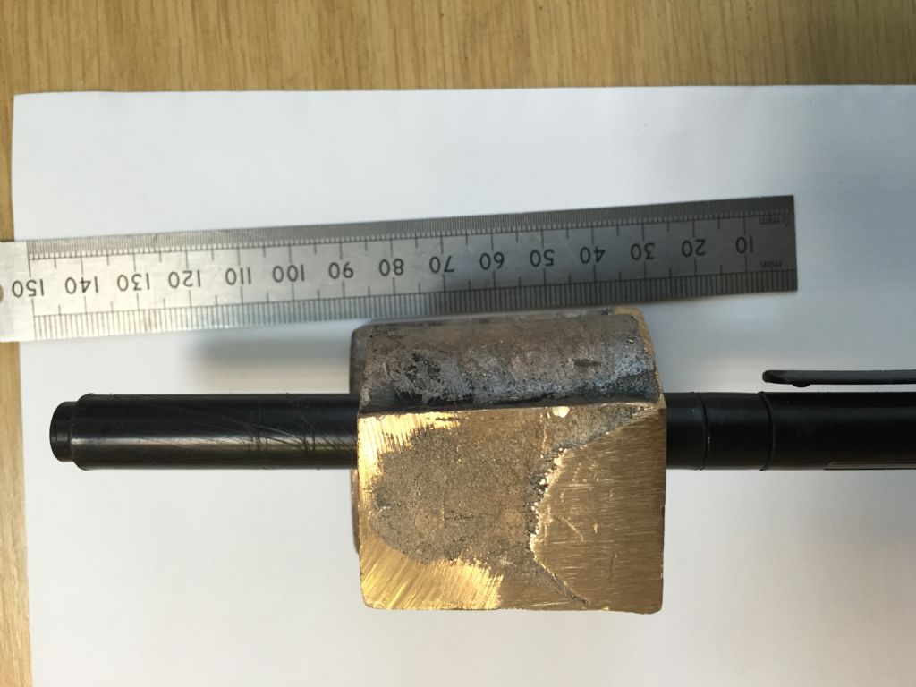
        Bit worried because the casting seems to have a taper down the one side, not sure if i should try and machine the radius.

        img_4147.jpg

        #249903
        JasonB
        Moderator
          @jasonb

          I ended up machining every surface of mine. Leave the outside until later then you van mount it on a simple arbor and take a few passes over teh curve to tidy it up.

          Is your casting just the cylinder block without the saddle?

          #249905
          Brian Abbott
          Participant
            @brianabbott67793

            Hello.

            Yes its got the saddle on, its not a very clear picture sorry,

            as you say i will machine the 2 bores, then try and true the rest up to it.

            Thanks.

            #249909
            Maurice Cox 1
            Participant
              @mauricecox1

              Hi Brian, just measured the gauge glass on my Stuart fitting, its slightly under 3/16" dia. Stuarts list 3/16" gauge glass, 2 off 3" pieces for about £4.50

              Maurice

              #249919
              Richard S2
              Participant
                @richards2

                Hello Brian, I'm sure the Cylinder casting has plenty of spare 'Meat', so don't be worried about the taper.

                If you first measure up the smaller end and set up to start machining that smaller face and then the bore, you will be ok.

                I think I have a few pics that may help later, but like Jason, they were before Digital and the WWW !. I'll dig them out and scan them for you if it will help.

                Regards

                #249947
                Brian Abbott
                Participant
                  @brianabbott67793

                  Hi Maurice, thanks for the info, yes i got some in the end from Stuarts.

                  Richard, if you would not mind scanning them for me when you get a chance i think it would help me.

                  Thanks all.

                  #249957
                  mal webber
                  Participant
                    @malwebber91786

                    Hi Brian, there is a build log of a 1" minnie on Traction Talk and the cylinder seems to be the latest couple of posts. hope this helps.


                    Mal.

                    Edited By mal webber on 08/08/2016 23:21:39

                    #249958
                    julian atkins
                    Participant
                      @julianatkins58923

                      Hi Brian,

                      I have a large quantity of gauge glass. If you know exactly what size you require I am sure I can find a length that suits.

                      Cheers,

                      Julian

                      #249964
                      Richard S2
                      Participant
                        @richards2
                        Posted by Brian Abbott on 08/08/2016 22:03:36:

                        Richard, if you would not mind scanning them for me when you get a chance i think it would help me.

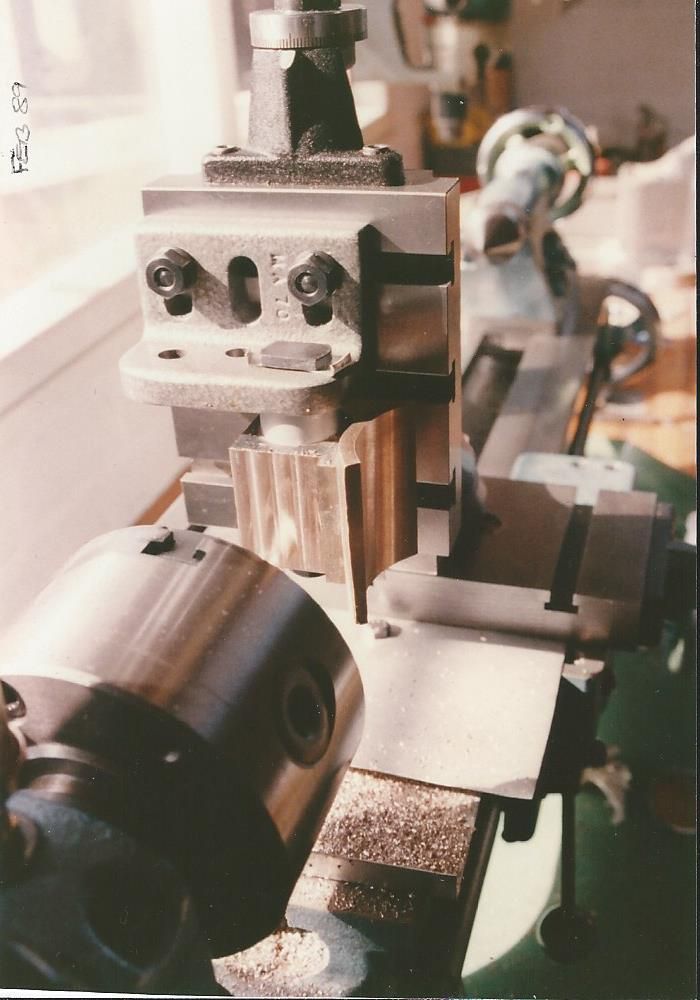
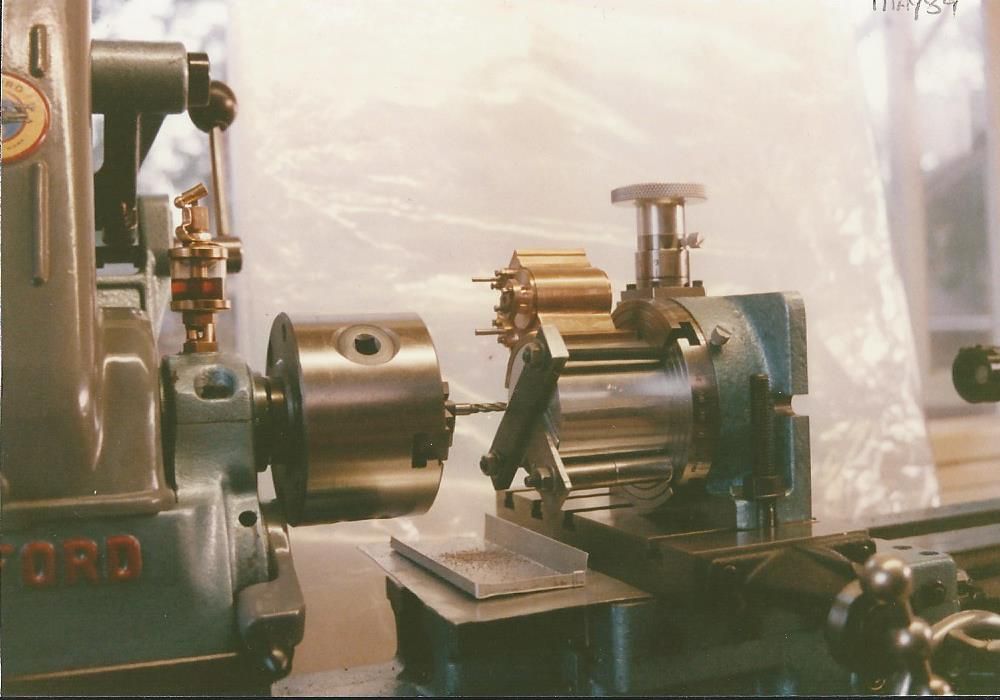
                        Ok, found 2 pics that may help, sorry about quality. Don't know your equipment stock levels, but the pics should be self-explanatory….if not-

                        I used the Vertical Slide for most of the faces, including fly cutting the saddle underside using a 1. 3/8" dia boring bar between centres.

                        In this pic, you can see the thickness of the Saddle face is also tapered (top face not yet machined). Taper is there for a reason and built into the Pattern for retraction from the casting mould.

                        cyl machining.jpg

                        I used a 4" Rotary Table to machine the top faces of the Saddle (and drill the bolt holes). In this pic the Cylinder is bolted to a slice of machined-to-size Aluminium Bar rather than Mr Mason's method.

                        Set ups may be crude in workshop procedures, but all went fine and accurate for me… being a Dabbling Novice.

                        Hope this helps. Regards.

                        #249965
                        Richard S2
                        Participant
                          @richards2

                          Sorry , forgot the other picblush. Not used to no Preview facility….cyl machining 2.jpg

                          #250039
                          Brian Abbott
                          Participant
                            @brianabbott67793

                            Hello all.

                            Thanks for the info, found the build on the traction talk website,

                            Photos are great Richard, looks like i need to machine the casting all over so the run out should not be a problem so long as there is plenty to clean up.

                            Julian. i managed to get some 3/16 from Stuarts so i should be ok, but thanks for the offer.

                            Cheers.

                            #256827
                            Brian Abbott
                            Participant
                              @brianabbott67793

                              Hello all.

                              After some more advice please.

                              In the process of making the water gauge ( still ) and i need to make some washers just to allow me to nip up the fitting at the correct angle.

                              Should i make these from copper or would aluminium be ok ?

                              Thanks.

                              #256830
                              Mark P.
                              Participant
                                @markp

                                Hi Brian, personally I would use copper washers as spacers.
                                Regards Mark P.

                                #264604
                                Brian Abbott
                                Participant
                                  @brianabbott67793

                                  Hello All.

                                  Can i please ask some advice regarding the positioning of the tender on my 1" Minnie.

                                  Should i.

                                  Position the bottom edge of the strengthening plate level with the bottom edge of the horn plate and spot the holes through.

                                  Then position the top edge of the strengthening plate level with the top edge of the tender side and spot through ?

                                  Thanks for any help.

                                  #264608
                                  JasonB
                                  Moderator
                                    @jasonb

                                    Can't remember how I did mine but probably as per the book which says mark both out from the hornplates.

                                    So I would do as you say for the strengthening plates and while they are against the hornplates mark their top and front edges on the hornplates.

                                    Then slip the tender over the hornplate and position it to these lines and then mark it from the holes in teh hornplates.

                                    With both the strengthening plates and tender drilled the draw strap is clamped between the two and marked out.

                                    #265171
                                    Brian Abbott
                                    Participant
                                      @brianabbott67793

                                      Thanks Jason,

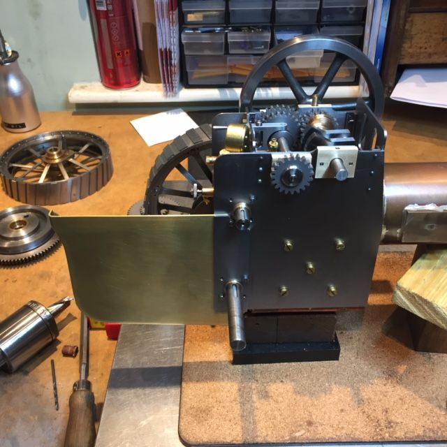
                                      Did as said and seems to have worked ok.

                                      img_4704.jpg

                                      #268816
                                      Brian Abbott
                                      Participant
                                        @brianabbott67793

                                        Hello all.

                                        Quick question if i may, there are 5 rivets shown holding the draw bar to the tender,

                                        Do the 4 outside rivets pass through the draw bar, draw straps and the tender back or just the draw bar and strap.

                                        Not sure reading the book, calls for 1 copper center rivet and the others to be iron.

                                        Thanks,

                                        #268855
                                        Richard S2
                                        Participant
                                          @richards2

                                          The rivet holes for the Draw Bar will be drilled (eventually) right through. The iron rivet heads inside the water space will need a good Tinning with solder when you're ready to 'Caulk' it up (2nd paragraph pge 120).

                                          Copper Rivet is for locating/positioning. 4 Iron rivets are to take/transfer tow loads from Draw Bar to Tender/Axle Bearings via Draw Straps , so no significant load/stress is applied to the Tender Joints etc.

                                          Look's like you're making good progress with the forming of the Tender Sides.

                                          One point worth considering is to clean and prime the inside faces of the Draw Straps and Draw Bar before finally riveting them on. It will prevent/reduce rusting risk when finished. I use(d) ordinary Auto spray Primer (lightly), which withstood the Soldering temperatures ok.

                                          Regards

                                          #268857
                                          JasonB
                                          Moderator
                                            @jasonb

                                            I went the other way and CSK the rear of the drawbar for the outer pairs of rivits. This is more inline with full size wher the drawbar is not fixed to the rear of the tender but just supported vertically by brackets and retained by the draw straps from any load pulling at it.

                                            #268956
                                            Brian Abbott
                                            Participant
                                              @brianabbott67793

                                              Thanks both for the advice, think i may go for the option of just riveting the draw bar to the draw strap and leave going through the tender back, but will probably change my mind my the time i get to it..

                                              #271460
                                              Brian Abbott
                                              Participant
                                                @brianabbott67793

                                                Hello all.

                                                Working on the water pocket back plate

                                                Can anyone offer any advice on how to drill the small hole for the hinge pin.

                                                So far i have broken 3 drills and scrapped the first back plate.

                                                Thanks in advance,

                                                Brian

                                                #271483
                                                Richard S2
                                                Participant
                                                  @richards2

                                                  I didn't follow the book on this part. I used 18 gauge for the back plate and 20g for the Body/Lid.

                                                  It meant I was able to avoid drilling the holes!.

                                                  I used 1/16" diameter brass tube and silver soldered it to the edge of each piece and carefully cut/filed to fit the 2 hinge pieces together. 1/32" dia pin joins 'em up. Not sure what metric sizes are around now, but you can make your own tube to size with less risk of breaking Drill bits.

                                                  I managed to make tubes for my 1/4" square Oil Box Lid hinges down to 1mm dia with 0.5mm bore on the old Peatol (Taig) no breakage-

                                                  dsc01552.jpg

                                                  #271490
                                                  JasonB
                                                  Moderator
                                                    @jasonb

                                                    Can't remember how I did mine now but it is to the book.

                                                    Few thoughts

                                                    1. thin down some flat brass section as this is a harder brass than if you use sheet so less snatchy

                                                    2. leave parts oversize until you have the hinge working then if anything wanders it can be accomodated

                                                    3. drill the backplate from either end, don't try going right through

                                                    4. as said solder tube to each edge and then mill the knuckle which is how these oil pockets are done

                                                    5. use thinner material and form the "hole" by bending the metal round, the hasp and staple here is about half the width of the water pocket

                                                    #271730
                                                    Brian Abbott
                                                    Participant
                                                      @brianabbott67793

                                                      Thanks both,

                                                      Going to try soldering the tube idea, see how that goes.

                                                    Viewing 25 posts - 126 through 150 (of 322 total)
                                                    • Please log in to reply to this topic. Registering is free and easy using the links on the menu at the top of this page.

                                                    Advert

                                                    Latest Replies

                                                    Home Forums Traction engines Topics

                                                    Viewing 25 topics - 1 through 25 (of 25 total)
                                                    Viewing 25 topics - 1 through 25 (of 25 total)

                                                    View full reply list.

                                                    Advert

                                                    Newsletter Sign-up