Is anyone else trying to build one of these engines? The mistakes in the drawings for the crankcase in Part 1 are obvious, but the components in Part 2 are a bit more problematical.
Part 1: No dimension is given for the width of the top face. Somehow I ended up at 1.688, (11/16". But, it's not too critical.
Part 2 is more involved and has a lot of errors I'll try to explain them. They are only for those components that I have tried to make, so there could be others!
Liner.
The 0.075 dimension for the top of the exhaust port from the underside of the flange is smaller than the dimension of the exhaust port! I think it should be the thickness of the flange.
Transfer Port: No dimension is given for the top of the port where it enters the bore. Or do we have to guess that it's level with the bottom of the exhaust port? Also do we guess where to start cutting – at an angle – so as to get the cutter to just hit the corner of the flange and enter the bore just level with the exhaust port? What size cutter would I use? The photos show the set up the author used. It's a simple set-up with the liner clamped to a vee block. How did he rotate it to cut the three ports as slots?
Cylinder Fins: The bottom of this component is not like the GA! If it's made to drawing then the exhaust port bottom edge is 0.08 above the bottom edge of the exhaust port in the Liner. That's half the height of the port! I have made mine to match the GA
Cylinder Jacket: Having made this to drawing I found that it was well nigh impossible to get the four M3 screws holding it to the crankcase in place and then tighten them. The photos show cap head screws. I have tried all types of screws but, in the end, gave up. My solution was to machine four scallops in the top flange to allow the screws to be inserted and the hex key – with a 'ball' end' – to be used to tighten them. Of course, this means that the four long screws used to fasten the head and fins in place will need to be placed 'fore and aft' and 'across' the engine, but I don't think that will be a problem.
It would have been very useful to have had a Materials List in Part 1. This should have included the sizes and lengths of the screws.
My Replies in bold but I will also ask Diane to get Chris to comment
Part 1: No dimension is given for the width of the top face. Somehow I ended up at 1.688, (11/16" ). But, it's not too critical.
Yes does seem to be missing but 1 11/16" looks to be ok on a non critical part
Part 2 is more involved and has a lot of errors I'll try to explain them. They are only for those components that I have tried to make, so there could be others!
Liner.
The 0.075 dimension for the top of the exhaust port from the underside of the flange is smaller than the dimension of the exhaust port! I think it should be the thickness of the flange.
Agree looks like the flange thickness
Transfer Port: No dimension is given for the top of the port where it enters the bore. Or do we have to guess that it's level with the bottom of the exhaust port? Also do we guess where to start cutting – at an angle – so as to get the cutter to just hit the corner of the flange and enter the bore just level with the exhaust port? What size cutter would I use? The photos show the set up the author used. It's a simple set-up with the liner clamped to a vee block. How did he rotate it to cut the three ports as slots?
Yes it would be nice to have height of transfers, hard to decide if top of port lines up with bottom of exhaust or passes through junction of flange and OD of liner. 3.5mm or 9/64th cutter would be about right both readily available in FC-3 type which are quite cheap. I would say they are straight slots and not cut radially, simple bit of indexing in the 3-jaw prior to milling would give the spacing
Cylinder Fins: The bottom of this component is not like the GA! If it's made to drawing then the exhaust port bottom edge is 0.08 above the bottom edge of the exhaust port in the Liner. That's half the height of the port! I have made mine to match the GA
Yes quite a difference there though the photo No24 is as per drawing
Cylinder Jacket: Having made this to drawing I found that it was well nigh impossible to get the four M3 screws holding it to the crankcase in place and then tighten them. The photos show cap head screws. I have tried all types of screws but, in the end, gave up. My solution was to machine four scallops in the top flange to allow the screws to be inserted and the hex key – with a 'ball' end' – to be used to tighten them. Of course, this means that the four long screws used to fasten the head and fins in place will need to be placed 'fore and aft' and 'across' the engine, but I don't think that will be a problem.
Can't agree with this as the photos definately show hex head bolts. but if you want to use cap heads then grind yourself up some short keys for final tightening the rest can be done with ball ended drivers
It would have been very useful to have had a Materials List in Part 1. This should have included the sizes and lengths of the screws.
I tend to just by boxes of 200 cap heads at a time and cut them to suitable length which works out a lot cheaper than buying small quantities of various lengths.
Transfer Ports: The height and position in the bore is critical as this affects the timing on a two-stroke engine. They are straight slots radially disposed around the bore of the liner. They are angled upwards at 45 degrees and this gives a problem in determining where to start the cut if the ports are to end up in the right position. To make the slots the liner needs to be rotated. The photos of the set-up shows no means of doing this – there is no rotary table or three-jaw chuck. A 3.5mm cutter is just a few thou under the size of the ports – 9/64" is just over. Moving the mill's table across will result in a crescent shaped slot with the ends of the slots upwards towards the top of the cylinder bore. Perhaps this won't matter, perhaps it will, perhaps I'm worrying too much.
Cylinder Jacket: You are correct – a look at Photo 27 is the clearest. However, I tried every type of screw except hex headed – I haven't got any M3 ones – and found it almost impossible to get them in and start to turn them. I used ball ended hex keys but they have to be used at too shallow an angle to work and I do have keys with short ends to get into places with low headroom. Cutting the four scollops allows the screws to be easily inserted and whatever driver is needed to be used almost vertically.
Materials List: I always buy screws and the longest length I can and in large quantities. They are easily cut down – just screw a steel nut on, saw to length, tidy up sawn end on the linisher, remove nut to clear thread at end – but not easily made longer! Having a materials list would have made it easier to determine if my materials store at home had the required chunks of aluminium or the right grade and lengths of steel so that whatever I might need could be sourced at Ally Pally at the end of January.
Reply back from Chris, He will also post later this moring.
Diane has asked me to contact you 're the drawing errors, most of which are due to me not having the chance to check the drawings before printing and which l am very sorry about.
The engine was built by someone else to prove my originals were ok.
I am waiting for a password reset for the forum.
1 The crankcase width should be shown as 1.80, a bit less is ok.
2The recess in fig2 for the bearing flange should be .02 not .20
3 The crankcase main bore should be 1.32
4 For fig4 in part 2, the .075 dimension should refer to the flange thickness, the arrow is in the wrong place.
5 The transfer ports should be positioned as shown as close as possible to the flange underside.
6 The GA drawing is wrong, the liner flange is not recessed into the fins.
7 On the conrod the ends should be aprox .37 dia.
I must admit the last two items were my error, not picked up by the prototype builder.
Please feel free to post this lot on the forum, when l can sign in l will comment also.
Posted by Dick Ganderton 1 on 23/02/2017 00:46:34:
this gives a problem in determining where to start the cut if the ports are to end up in the right position
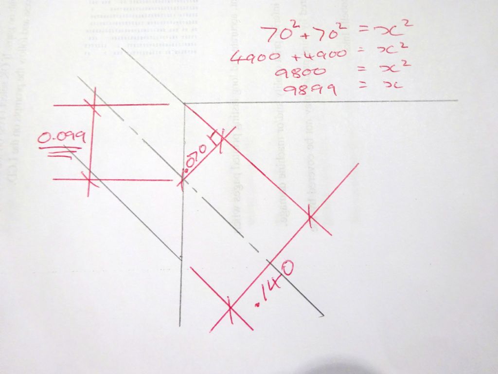
As Chris has now confirmed the crest of the slot should be as close as possible to teh underside of the flange, a quick bit of trif will give you how far down the ctr of the hole should be, for 45deg its easy to do 0.707 x 0.140 = 0.099" below flange, this can be marked with a height gauge and then picked up with a wobbler or sticky pin
A 3.5mm cutter is just a few thou under the size of the ports – 9/64" perhaps I'm worrying too much.
Yes I think having a cutter that is 0.0006" oversize is worrying too much.
Cylinder Jacket: You are correct – a look at Photo 27 is the clearest. However, I tried every type of screw except hex headed – I haven't got any M3 ones – and found it almost impossible to get them in and start to turn them. I used ball ended hex keys but they have to be used at too shallow an angle to work and I do have keys with short ends to get into places with low headroom. Cutting the four scollops allows the screws to be easily inserted and whatever driver is needed to be used almost vertically.
The best way is to put the screws into the jacket befor offering it upto the engine, that way they will drop down so the underside of teh heads rest on teh flange and give you some room above the head. You can then work your way around the screws tightening each a turn or two and pull the jacket down as you do. As the liner can be used to locate the jacket the clearance holes can be a bit larger than normal which helps to put teh scre winto the hole
Materials List: I always buy screws and the longest length I can and in large quantities. They are easily cut down – just screw a steel nut on, saw to length, tidy up sawn end on the linisher, remove nut to clear thread at end – but not easily made longer! Having a materials list would have made it easier to determine if my materials store at home had the required chunks of aluminium or the right grade and lengths of steel so that whatever I might need could be sourced at Ally Pally at the end of January.
The exhaust ports in the liner and fins do not line up exactly, but the recess around the bottom of the fins allows the exhaust gases to expand as they leave the liner port, to reduce restriction.
Regarding the screws used to assemble the crankcase, l used 6ba hex heads but as ba sizes are not easily available in many countries, l put metric on the drawings, as the sizes are similar.
I prefer industrial quality fixings, which tend to be made of stronger steels than model supplier ones.
Chris. 6BA screws are smaller than M3 – which probably explains why you were able to get them in. I had to reduce the head diameter of all the screws I tried by around 0.03" to miss the wall of the jacket. 5BA would be a better equivalent to M3. I decided to use cap head M3 stainless screws throughout.
I prefer the bottom of the fins as shown in the GA – it just looks 'more correct'. Anyway, I have made it now and don't intend to make another one. At least my exhaust ports will line up!
I tried the trick of fitting the screws in the holes first but that didn't work either. The liner cannot be used to locate the jacket for two reasons – it doesn't reach down as far as the crankcase and it's a smaller diameter than both the bore of the jacket and the hole in the top of the crankcase. I turned up a locating plug from an odd bit of steel bar with the two diameters and just drop this in place.
The transfer ports are 0.140" diameter so the centre of the cutter will need to be 0.049" below the bottom of the flange.
Posted by Dick Ganderton 1 on 23/02/2017 18:52:54:
The transfer ports are 0.140" diameter so the centre of the cutter will need to be 0.049" below the bottom of the flange.
Can't get it to come out as that, as I said basic school boy maths gives 0.099"
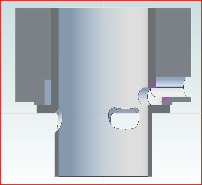
Also CAD seems to agree
Pink areas could be touched up with a Dremel if you want a clearer gas flow, but this is not a high performance competition engine so probably not worth bothering.
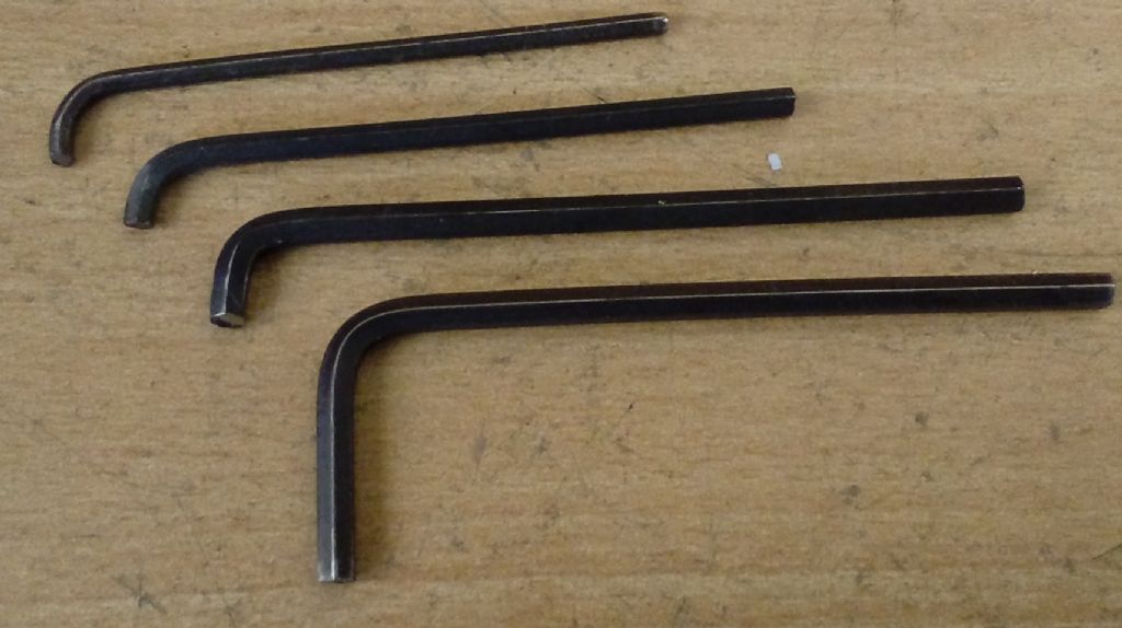
As for hex screws, the ones I use would fit fine, I don't by the cheap ISO metric hex sizes which for M3 would have 5.5AF heads but spend a little more on the ones specifically made for model engineers which have 4.0AF so would be able to rotate OK
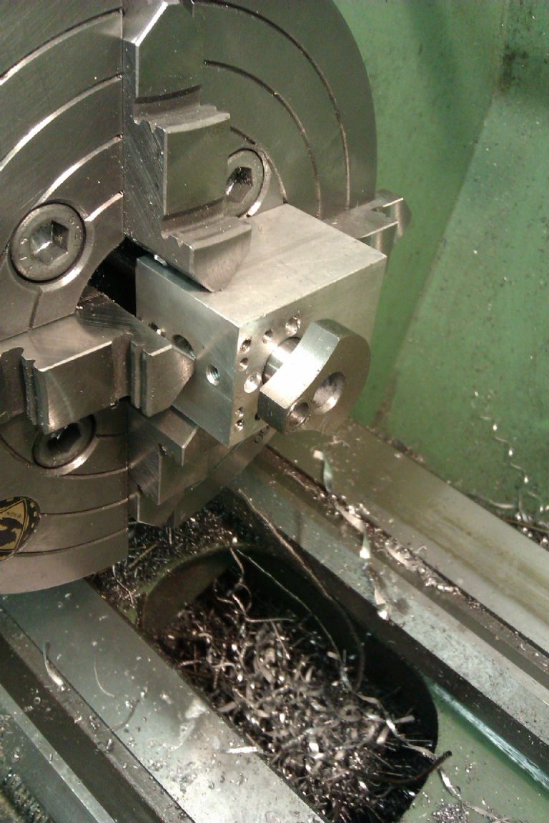
On the subject of transfer ports, and all other machining operations on the 49 engine, I always use the most basic set ups , I do not own a rotary table, and try to assume many other builders will not have expensive equipment.
My previous engine articles were written for model aircraft magazines rather than ME, so the engines were first time projects for many people.
The exact width of transfer ports is not that critical, we are not trying to make a high performance racing engine. My ports were cut with a 3/16 cutter, and smoothed off with a file, the liner held in a vee block and repositioned by hand during milling, hence uneven edges before filing smooth. i .
A bit of clarification on the cylinder jacket top end. The 1.58 dia is the o.d. of the top part which projects .025 above the upper flange, the recess for the liner is 1.30 dia. See fig 7 on page 85. This is not very clear as shown.
Yes I have finished my engine but I can’t get it running for more than a couple of seconds. I am going to strip it and re measure, as I don’t think the fuel is getting into the combustion chamber in sufficient quantities.
Just got back to continuing with the engine. I am making the crankshaft and have got to the point where I need to shape the crank end. Should the radius at the root of the cut away portions be 0.125" radius rather than 0.25" rad? O.25" rad implies a 0.5" dia cutter. It also makes the end of the 0.5" 'arm' completely rounded off getting very close to the crank pin hole.
I have made another cylinder jacket and have managed to get the fixing screws in by making them as short as I dare and machining the head diameters so that they clear the wall. 6BA would definitely be better than M3 but having already drilled and tapped the crankcase for M3 there is no going to 6BA.
I haven't managed to find a source of small hex metric screws. Any suggestions?
Just email to me doc@hnpl.net your drawings. Ill go through it, add any missing dimensions and tips on what fits are actually needed etc so that when you make it, it will run.
The first anniversary of my retirement and house move has just passed so I thought it was about time to get on with some interesting projects over the winter (the house renovation project has been re-baselined accordingly). I had started on this model and now want to get on with it, hence this, my first post.
Before I produce any more swarf, I thought I would ask again if anyone has got one of these finished. If so are there any more tips? One difficulty I can see is in drilling accurately for the crankpin and getting it square but maybe I am worrying too much.
If you drill the crankpin hole as Chris shows using a vee block in the lathe it should come out square. You can also use a keats Angle Plate or a simple block with ahole in it that can be offset in the 4-jaw, a couple of grub screws with soft aluminiun packing down the screw hole first will protect the machined surfaces.