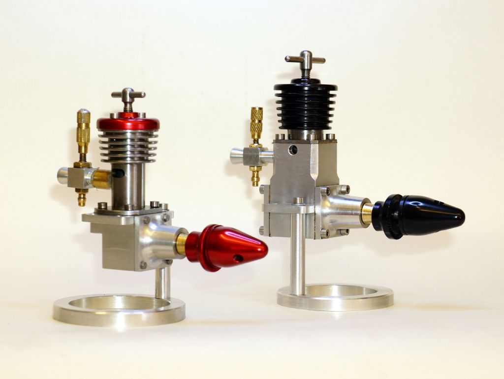
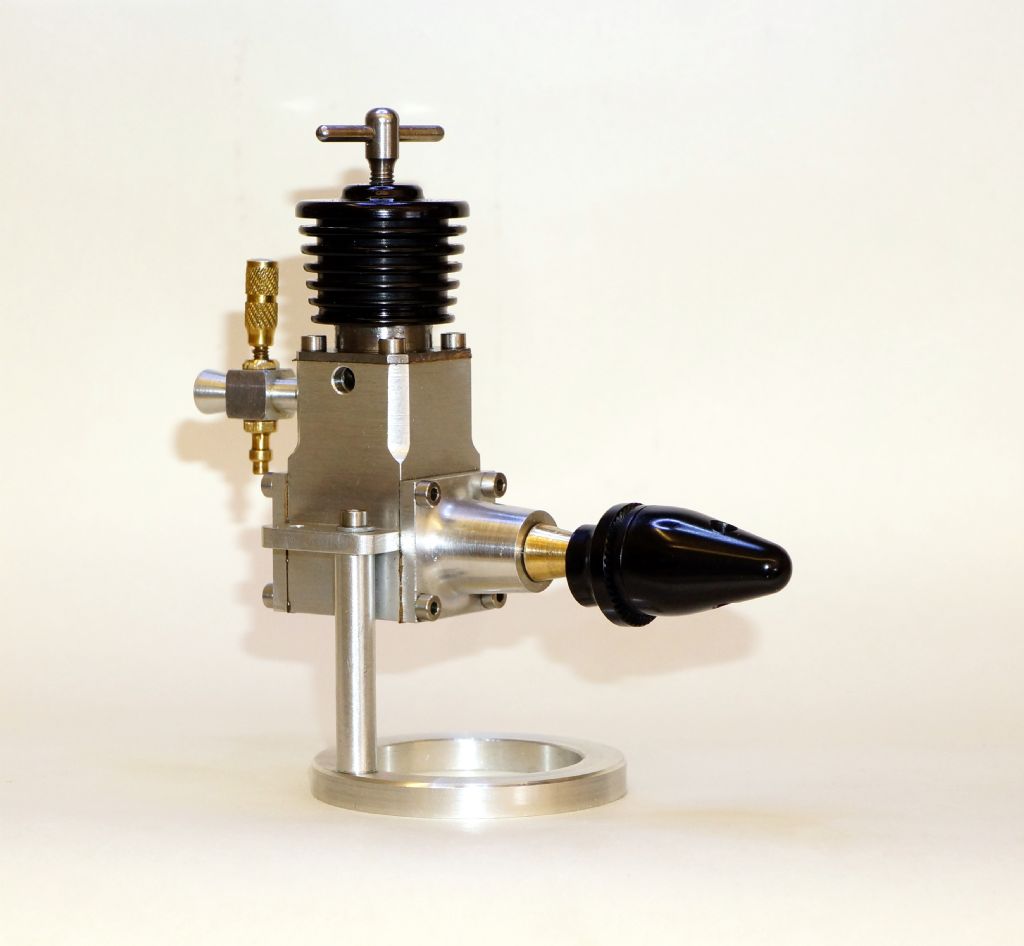
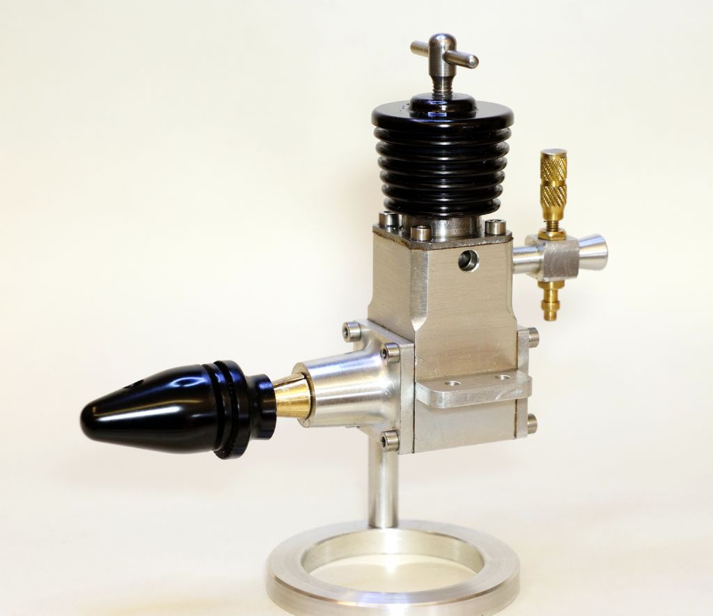
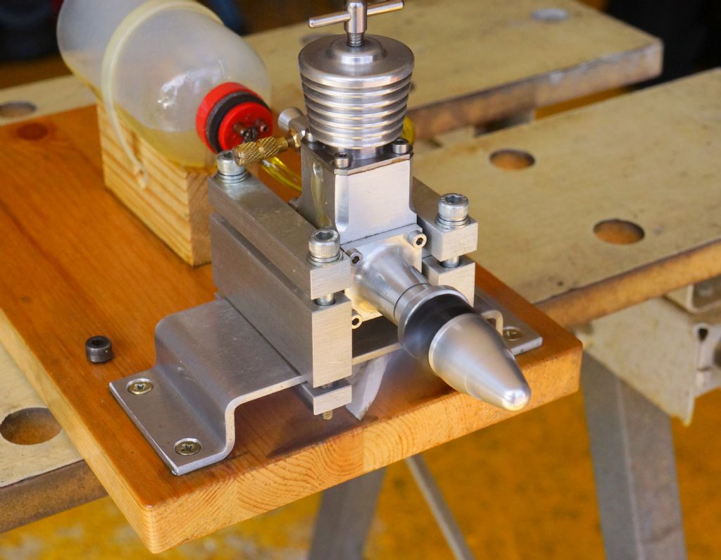
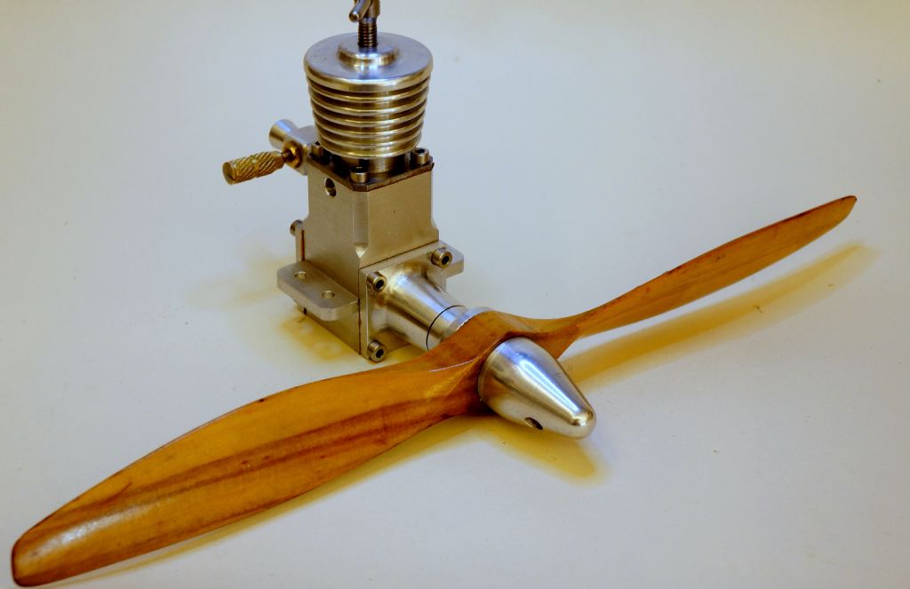
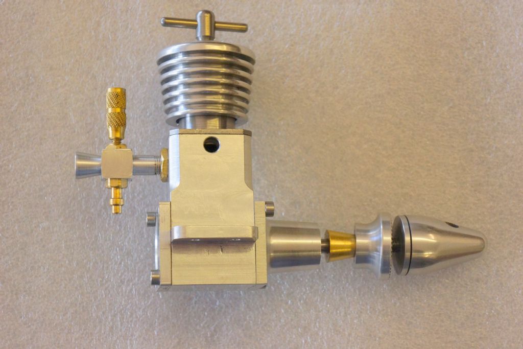
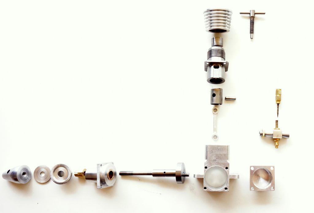
These are photos of my latest model engine build. After the successful making of the Chris Boll designed Cicada,I thought I would follow up with another of his designs for which drawings are freely available to download and are designed to be made from bar stock. The Bol-Aero has radial mounting and this does not fit well with my test mount set up, so I decided to make the crankcase with standard beam mounts. The carb, as drawn, is mounted on the side of the crankcase and would also not be compatible with my test mount, so that was moved to the rear face. This gave the opportunity to have another exhaust port, but this meant moving the fuel bypass to the front of the liner, and, so it went on. As every part came up for scrutiny before machining,I found one mod was leading to another and the finished engine only has the bore, stroke and timing of the original, plus the backplate of the crankcase is "as drawn" and that is all.
I had no problem finding the compression point that fires it up and it started on about the third flick. After 6 short 3 minute runs, cooling down between each, it is happily running at around 6500 RPM with a "8×4" nylon propellor. At this stage I decided to make it pretty and sent the cooling fins, prop driver and spinner to my friendly anodising firm for the black finish, with which I am very pleased. As my initials are J K B, I thought I might be cheeky and describe this as the "J K BEE" version of the BOLL-AERO 1.8 diesel.
Thank you Rod, Jason and Ramon, for your comments. They are much appreciated.
An example of how one mod created the need for another is with the original piston. It is always my practice to finish machine the piston inside shape, leaving the outside 0.020" oversize and then part off. The piston is then bonded with super glue to a mandrel made to fit the inside shape. This mandrel is drilled right through and a short thread put in the back end to take a cap head. and by inserting a short pin the cap head is then used to push the piston off the mandrel when heat is applied. All finish machining of the ouside and honing and lapping is carried out from this mandrel. The original internal shape of the piston is by drilling only. Hence the internal top shape is the 118 degree cone from a drill. Having lapped it to perfection,I proceeded to apply heat and screw the cap head and was appalled to see the pin in the mandrel,push straight through the top of the piston! I made a new piston, this time to the conventional internal slotted shape, plus I added .050" to the top thickness. To compensate for this and keep the timing the same, I milled a .050" deflector notch in the front edge,similar to a Mills 1.3cc. Also shortened the contra piston by the same amount. Whether this has improved performance I have no idea ,but it is fun solving such a problem.
I should add that, having made the piston heavier, I took 11 grams off the weight of the previously circular crank web,to compensate. I have not carried out any weight measurements for balancing , but the engine runs with minimum vibration.
If it helps to offset some of the pain of the extra troubles, I think your redesign was absolutely worth it – it looks very well indeed. The proportions and "black" look spot-on. Nice.
I can report an interesting (to me) development. Normally I make crankshafts from one piece of EN8.This time,as I was in the experimental mood, I built it in three pieces.The shaft from silver steel and threaded to a shoulder to receive an EN1A web,screwed on tight and silver soldered Crank pin was pressed in with a .002" interference fit. All looked good and made with minimum swarf. Yesterday,as the weather was cooler and I could have the door open, I thought I would have another test run or two, First 3 minute run,no problem. After cool down, attempt another and got a backfire that loosened the prop, Tightened this up, Next flip,single pop and the prop slowly came towards me, pulling the shaft of the crankshaft with it. It has sheared cleanly at the face of the web. When it was silver soldered I let things cool down slowly and did not attempt any further heat treatment. I did leave a .020" radius in the corner of the shoulder.. I have no informed knowledge of the stress loads at the point of failure and hope someone might suggest a reason for for it. Perhaps silver steel is not the right material
It has sheared cleanly at the face of the web. When it was silver soldered I let things cool down slowly and did not attempt any further heat treatment. I did leave a .020" radius in the corner of the shoulder..
The original shaft drawing is totaly different from what I made.
I am interested in the fact that you think the backfire started the problem. It is quite common to get backfire when starting diesels and I have some scars to prove it. Have you any opinion regarding my use of silver steel?
The replacement will be machined from one piece of EN8.
I've not used silver steel in any of my engine builds Keith but I would think it likely that root of the problem was the heating for soldering. The action of the back fire may have been the cause of the breakage but the steel had to be brittle in some way – heat the likely source. Silver steel is centreless ground – not as round as you might think and not truly ideal for crankshafts. Far better to do as you plan and machine from solid or ….
I make my crankshafts from EN24t but often make them composite – the web, pin and main shaft machined from solid and use caphead screw material for the central part from the web out to the prop mount. I did this on my first engine in order to preserve the small amount of En24t I had at the time. All the engines built since have used the same method save one of the Eta's and the latest Olivers (that due to them being front intake).
En 24T is hardened and tempered to a machinable state and makes for a very tough shaft but En8 should be okay and En16 even better.
I did hone and lap the surface of the silver steel, then made a bearing to fit. I think the fault did develop originaly when it was heated for silver soldering,as you say.. All good experience and an idea i had had for some time that will not be repeated..
Hi Keith, yes, put it down to 'experience' and keep it in mind for future. Having said I don't use it a far as I'm aware the only parts I have made from silver steel were the rotor pins for the Eta engines. These have a left hand thread that screw into the backplate and a shoulder for the tufnol rotor to run on.
Sometime back I took them to Old Warden to run – on cleaning them down the next day one of those pins just disintegrated at the thread relief as I was checking it's tightness. Despite very careful heat treat and tempering it was obviously not tempered enough. Could have made a nasty mess had that let go while running. Though I haven't got round to it yet I did buy some small dia EN24t to make some new ones to replace all of them.
With regards to the 'centreless ground' anomaly I was reading only recently on another forum that AM engine shafts (well in this case specifically AM25s) were originally ground between centres but in order to reduce costs they were then centreless ground – apparently they then exhibited a tendency to 'lock' until the shafts were honed.
Personally, silver steel is great for making cutters but I try not to use it for components if I can avoid it.
Hi Ramon, I do have a microscope and with difficulty have managed to get the web under it. I can see that the shear has started at the root of the thread, Silver steel always looks a bit rough to my eye when using a die to to cut the thread and the roughness is clearly a tearing action that can develop to a crack under load and heat..
Probably a subject for another thread, but I am now wondering why Stubs and others chose this steel particulaly, to offer it in centreless ground pieces. Wikipedia says it is a Tool Steel, often used for knife making.
For several years I worked with a variety of tool steels making small components for press tools. Silver steel was used but infrequently relative to others. In IMHO though, although it will turn quite well it is one of the more difficult to cut a thread on. As you have observed even when screwcut the thread is rough in comparison to other materials and for the greater part does have a propensity to 'tear' rather than cut. There is a 'freecutting version' but even that is not ideal. (I'm basing this on hand ground HSS tooling as opposed to any form of preformed carbide tip).
As far as I know it has always been centreless ground – to the naked eye it does look like a nice piece of material to use for shafting but the material is really designed for through hardening so there are much better options available.
As said I do use it for making tools but despite it being recommended as 'water hardening' ie quenched in water I always quench in oil to offset any cracking (again this is from work based experience)
It's always tempting to make things a little easier by making the web and main shaft separate parts but if this can be made from one piece so much the better in my view.
Looking forwards to hearing how the new shaft performs – always like to hear of other makers progress with these lovely little home built engines
I have experienced the same "tearing" of threads when cutting silver steel even with full formed inserts and all variations of depth of cut and speeds. Even when using a HSS die to finish the crests when not using form inserts.
I can see that the shear has started at the root of the thread,
Keith
Look at the last picture in largest browser enlargement.
What happened was that it started to break opposite the thread root.
You can see five or six striations.
It was figthing.
When no 7 overload came all of the rest broke.
It was simply to much.The last part to break was the thread root that had been in compression when the top fought in tension for dear life of the rest.
Keith – commiserations! ..although from a slightly ghoulish perspective, very interesting and informative. I made an initial start on the same engine some weeks ago, and although not managing to progress quickly with it, it's enlightening to actually see physical evidence of the levels of stress that some parts are under. Best wishes for a successful conclusion..