Boat hull formula

Advert

Boat hull formula

Viewing 25 posts - 1 through 25 (of 49 total)
  • Author
    Posts
  • #512095
    BOB BLACKSHAW 1
    Participant
      @bobblackshaw1

      Hello, I have made the engine and near finishing the boiler for the tug boat I am making. I am to start on the hull but would like a formula to see if it will float at the correct line after all the parts are installed. The problem is that I am making the hull out of 16g copper cut into strips and soldering up to 18g steel formers. I have a 1/2 sheet of copper that will never be used and it will be easy to work around the shapes needed. But I worried that after making it with all the parts in will it be to low in the water, is there a formula that can be used to determine this problem .Hull size is 30 inches x 7.6 inches, or will it be to heavy and sink

      Thanks Bob

      Advert
      #33744
      BOB BLACKSHAW 1
      Participant
        @bobblackshaw1
        #512100
        Ramon Wilson
        Participant
          @ramonwilson3

          Bob I don't know the formula but if I have my Archimedes principle right the total weight of the boat should not exceed the weight of the volume of water it displaces at the correct waterline.

          If you can work out that volume and convert to weight of fresh water that should tell you the total weight you can accept.

          A boat hull made from tinplate has been done many times but 16swg copper is obviously much heavier – given the size of hull I would not have thought this is a viable material to make a hull from.

          Conversely the lighter the hull can be made the more weight you can fit in it – important when using a boiler and steam plant.

          Regards – Tug

          #512102
          Bazyle
          Participant
            @bazyle

            Be very careful about making it top heavy aswell. For an idea of the weight have a look at other similar disgns (type/length) especially kits doing a search on the Model Boat and Mayhem forums and you will probably find some reference to the wieght.

            There used to be a beautiful tug sailed on the lakein St Albans of a design I haven't found on the web. The key point being that is was a small harour tug with a fully exposed engine – hence able to show off the scale fittins. The point being it was made with teh copper from a scrapped hot water copper cylinder. Not sure how thick that would be – especially as it was scrap due to corrosion.

            #512103
            Rod Renshaw
            Participant
              @rodrenshaw28584

              +! for Tug''s approach. and I agree with Tug's gut feeling that this hull is likely to be too heavy to float, especially if it is to have a steam engine and boiler.

              We don't have anything like enough information to calculate this in any scientific way, some boat hulls are much finer than others. Something box- like and deep ( like a barge) will have much more internal volume than a hull with a rounded shape and shallow draft , even though they have the same length and beam. Naval architecture is as much an art as a science and even the professionals get it wrong sometimes. Best to keep the weight to the absolute minimum, you can always add ballast, but not easy to take it away.

              Sorry to have doubts about this.

              Rod

              Edited By Rod Renshaw on 07/12/2020 10:09:14

              #512115
              Ramon Wilson
              Participant
                @ramonwilson3

                Without the correct formula(s) (and the knowledge) the only way is to take a calculated guess at it

                Bobs model is 30 OAL x 7.6 beam so if the draft is say 3 inches thats 684 cu ins. Obviously thats more than the hull due to its shape and curvatuures but lets say its displacement is around 75% of that – 513 cu ins.

                1 cu in of freshwater weighs .036 lbs so thats 18.46 lbs of displacement.

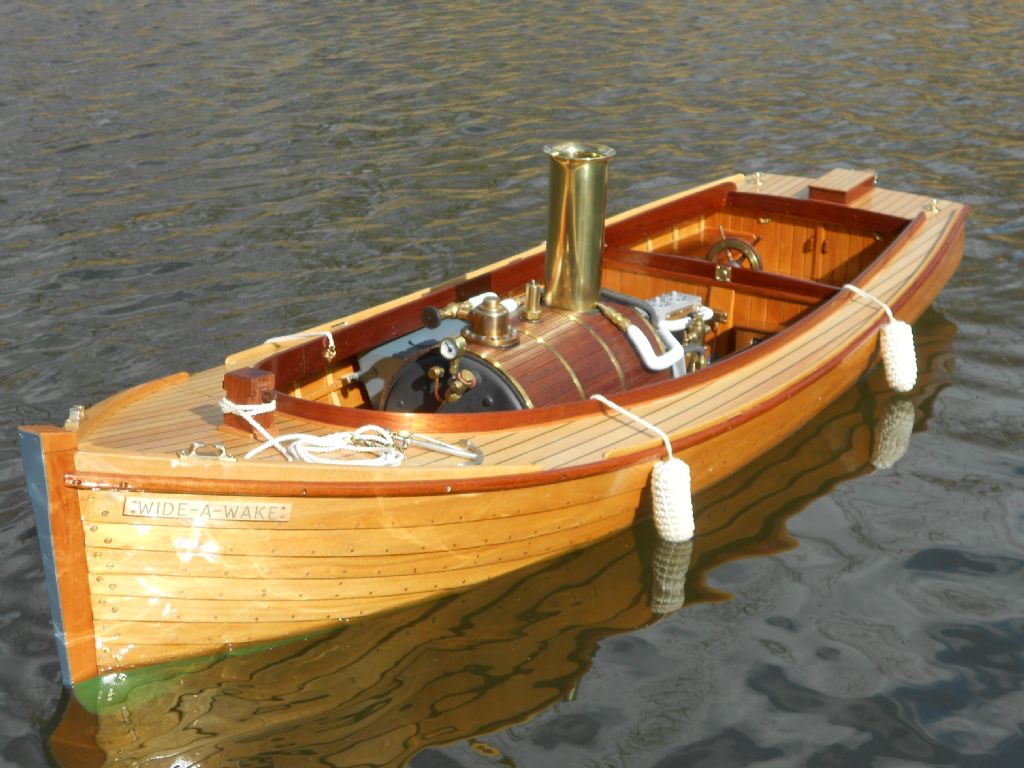
                I built the model Wide a Wake some time back. It's a 52" hull at 14 1/2" beam with a good sized volume of displacement. As built mainly in parana pine the hull is quite light for it's size. I don't know how much it weighs in total but once on the water with the boiler and feed tanks full etc but no extra ballast it sat a bit more below the anticipated water line than expected.

                Regards – Tug

                #512125
                Andy_G
                Participant
                  @andy_g

                  Look up ‘prismatic coefficient’ and ‘block coefficient’ – they won’t give you the answer, but should help estimating displacement. From a quick look, tug hulls typically have a block coefficient of 0.6, so will displace 60% of the theoretical length x beam x draught volume.

                  #512136
                  Ramon Wilson
                  Participant
                    @ramonwilson3

                    Thanks Andy – that's useful to know.yes

                    That makes Bob's potential hull displacement 410.4 cu ins = 14.77 lbs.

                    With due respect Bob I think you are going to have to try a different material.

                    Incidentally you may be interested in a series of articles in ME quite some time ago by a 'Don Gordon'. He set out to build a ship and plant as scale as possible. I think he used brass shim for the hull. Don was a member of the Norwich society so often got to see his microscopic attention to detail. I have no idea when they were featured but they may be worth searching out.

                    Regards – Tug

                    #512140
                    Journeyman
                    Participant
                      @journeyman
                      Posted by BOB BLACKSHAW on 07/12/2020 09:18:59:

                      … is there a formula that can be used to determine this problem .Hull size is 30 inches x 7.6 inches, or will it be to heavy and sink

                      There certainly is a formula, actually quite few. You could start with Simpson's Rules and it gets more complicated from thereon. I am afraid it is about 55years since I briefly studied Naval Architecture and all I remember was that it involved and awful lot of calculation (then with a slide rule). I think I would probably go with Ramon's method.

                      John

                      #512144
                      Rod Renshaw
                      Participant
                        @rodrenshaw28584

                        Don (DG) Gordon, ME 1975 -76, Vol 141-142, also 1980 Vol 146 and 1981 Vol 147.mostly articles on boilers and machinery for model steamships and paddle steamers. He does emphasise the need to keep the weight down.

                        Rod

                        #512146
                        JasonB
                        Moderator
                          @jasonb

                          If you are handy with CAD it should be possible to draw out the various hull profiles from the plan (can be traced in) at their correct spacing then loft through them all to get a 3D hull. Slice off the part above the waterline then let CAD work out the volume of what remains. Failing that work out the rough area of each rib below waterline and multiply by distance to the next one and add them all up.

                          Not had my hands on a fibre glass hull but would think they come out about a 1.5 – 2mm thick and are popular for tug boats. So with copper being 3-4 times denser that GF you may be sitting a bit low in the water unless these hulls are balasted?

                          Edited By JasonB on 07/12/2020 12:24:00

                          #512153
                          Ramon Wilson
                          Participant
                            @ramonwilson3

                            Thanks Rod – I remember his work as being perhaps a bit too unrealistic for a working model but you couldn't fault his approach nor workmanship.

                            CAD would be a very useful tool Jason as would the readily available software specific for this purpose but unless one is seeking perfect performance from the hull not really necessary in this kind of situation

                            A fibre glass hull for a 'tug' of which there are many available would be far more suitable but may not need ballast depending on the size. The 'Cruiser' hull I referred to in Bobs previous thread was fitted with electric motors but despite having two fair sized 12 volt batteries did require a fair amount of sheet lead ballast. This was chopped into very small pieces and set in epoxy to get the weight as low as possible – Bazyle hit the nail on the head here – top hamper is not desirable at any time.

                            BOB – Here are two pictures that help show the difference of weight to a waterline.

                            This was taken for the ME mag just after the WaW was finished but before the 'official launch'. It has some water in the boiler but not at working level and the water tanks are empty.

                            dscn0726.jpg

                            This however was taken on the day of launching proper but with the boiler and water tanks full. You can see the difference that made on the waterline. There is no ballast in this vessel.

                            wide a wake launch (15).jpg

                            Sorry to rain on your parade but hope that's of more use

                            Regards – Tug

                            #512163
                            Martin Kyte
                            Participant
                              @martinkyte99762

                              If you had something to use as a test tank you could rough out a hull from wood and test the displacement. You would also then have a test model to play around with to increase or decrease the displacement. Simple tank with an overflow to catch displaced water, then either weigh the water or measure the volume.

                              It could be done in CAD but if you don't hve the software, the old methods still work.

                              regards Martin

                              #512164
                              Former Member
                              Participant
                                @formermember12892

                                [This posting has been removed]

                                #512165
                                Keith Long
                                Participant
                                  @keithlong89920

                                  Bob if the tug that you are building is a scale model of a full size actual tug, look up the displacement of the full size vessel (internet search) and divide by the cube of the scale factor that you are building to, that will give you the weight that your model needs to be to float at the design waterline. If your model comes out lighter than that figure then you'll want ballast, if heavier then you might be better trying to loose some of the weight before you go too far. If the model is only slightly heavier than the "scale design" figure then don't worry too much, tugs can benefit from sitting a bit deeper to make sure that the propeller has enough water to "bite" on. Too much weight and then you're building a submarine!

                                  #512170
                                  Buffer
                                  Participant
                                    @buffer

                                    I started out training as a naval architect and I can tell you that you will need an awful lot of work to try and work that out. Far more than I could tell you on this by typing. Simpson rule is one way of doing it having measured the areas of all the frames. Personally I would not even try to do it but ballast it afterwards to get it to float level where you want it.

                                    #512194
                                    BOB BLACKSHAW 1
                                    Participant
                                      @bobblackshaw1

                                      Thanks for the replies on this,it seems that a lot more thought is needed as a lot of work could be wasted. Tug .the steam launch looks fantastic, a question when you planked the hull did you rebate the edge for the next plank to fit on. I have no wood working skills so that why I was looking at a metal hull.

                                      Bob

                                      #512204
                                      SillyOldDuffer
                                      Moderator
                                        @sillyoldduffer
                                        Posted by Buffer on 07/12/2020 14:25:06:

                                        Personally I would not even try to do it but ballast it afterwards to get it to float level where you want it.

                                        Bob's concern is that it might not float at all!

                                        What's needed is:

                                        • The volume of the space enclosed by the hull
                                        • The mass of the hull, machinery, and super-structure.

                                        The boat will float provided the volume of water displaced by the hull weighs more than the boat.

                                        As calculating the volume of a curved hull is hard work, I suggest estimating the volume by comparing it roughly to the size of a thin walled plastic kitchen jug, which is about 500ml. Imagine the empty hull. how many jugs could be squeezed in to the space?

                                        Assuming the boat was box shaped:

                                        30" x 7.6" x 6"

                                        is 0.762m x 0.193m x 0.147m

                                        which is 0,0216 cubic metres.

                                        As 1 cubic metre of water weighs 1000kg, the box shaped boat would support a maximum weight of 21.6kg (47.6lbs)

                                        That's the maximum possible, and as a sanity check the jug estimate should be less than that.

                                        Assuming the boat was triangular in cross-section, deck 7.6", with keel 6" below, and 30" long, then

                                        0.0144sqm x 0.762m = 0.011 cubic metres, which is a maximum weight of 10.9kg

                                        As your real boat has pointy ends, and probably has a full bellied mid-section, I guess it's displacement will be roughly between the two, say 16kg (35lbs) with no freeboard. Reducing weight by 25% suggests the maximum weight of the vessel should be less than 12kg (26lbs) Jug guessing should produce a better estimate.

                                        Re Copper vs Fibreglass, it's the weight that matters, not the density. Although Copper is denser than Fibreglass, you would likely use less of it because the hull could can be made thinner. Being used to wood, many people found it difficult to accept Iron ships could float. Actually, they floated better than wooden ships because iron is stronger, and much less of it was needed to make a satisfactory hull. Mild-steel is even better, and warships often used high-tensile steels to save weight, allowing more armour or higher speeds. Can you guestimate how much copper sheet will be used and weigh it. Copper's not a problem provided it's well within the overall weight limit.

                                        The easiest way to get an accurate result is to CAD model the hull because the computer calculates volumes and areas as an aside.

                                        Another way is to create the impression of the hull in clay and fill it to the desired safe water line with water. Each litre amounts to 1kg of weight.

                                        Next issue is stability. To avoid capsizing, heavy weights like the engine, boiler and batteries etch should all be blow the waterline. Everything above the waterline, like the bridge, funnel & masts should be kept light. Shouldn't be difficult because that's how the original was built.

                                        Full size shipwrights have to go an extra step. It's undesirable for all the weight in a ship to be too low because it results in violent rolling and everyone gets sick! By lifting the weight the ship becomes stiffer and rolls less. But not too high, because it risks capsize. Difference between the centre of gravity and the centre of buoyancy. Look up metacentric height if it's of interest. Probably doesn't matter how much a model rolls, and maybe the original had all the weight low down. Tug boats weren't built for crew comfort!

                                        Hope the sums are right – don't forget I'm terrible at maths…

                                        Dave

                                        #512220
                                        BOB BLACKSHAW 1
                                        Participant
                                          @bobblackshaw1

                                          Thanks Dave for your interest , I shall weigh the amount the hull will weigh in the morning including engine and boiler water etc, I'm finding this interesting

                                          Bob

                                          #512237
                                          Ramon Wilson
                                          Participant
                                            @ramonwilson3

                                            Well I'm pleased to see you confirm my thinking on displacement in some way Dave smiley but I think you are way off regarding weight and density.

                                            16 swg copper is what Bob intended to use – compare that to 1/16 balsa or even plywood strip of the same section and the weight difference is substantial. 'Build' two identical hulls one using copper and one using balsa – they will both displace the same if the total weight is equal but the balsa one can have far more weight added to bring down to the same water line as the copper one. What weighs more – a ton of lead or a ton of feathers – springs to mind.

                                            The lighter the hull is made the more it can be loaded for a given displacement /waterline.

                                            Bob, I put the two pics up for nothing more than to show the difference a slight increase in weight can create to a waterline. The model was serialised in ME and also a full build log was on MEM here which describes all the wood processes.

                                            Though you obviously have a desire to make it yourself, personally, if I were you, I would look into obtaining a fibre glass hull and fitting that out with your steam plant. You will still have an awful lot of very enjoyable work to do to accomplish that.

                                            Regards – Tug

                                            #512249
                                            SillyOldDuffer
                                            Moderator
                                              @sillyoldduffer
                                              Posted by Ramon Wilson on 07/12/2020 18:55:59:

                                              Well I'm pleased to see you confirm my thinking on displacement in some way Dave smiley but I think you are way off regarding weight and density.

                                              16 swg copper is what Bob intended to use – compare that to 1/16 balsa or even plywood strip of the same section and the weight difference is substantial. 'Build' two identical hulls one using copper and one using balsa – they will both displace the same if the total weight is equal but the balsa one can have far more weight added to bring down to the same water line as the copper one. What weighs more – a ton of lead or a ton of feathers – springs to mind.

                                              Regards – Tug

                                              We're in violent agreement Tug! Of course you're right, ¹⁄₁₆" balsa is lighter than 16swg copper. But the copper is stronger, potentially making it possible to reduce frames, keel and machinery supports. I'll do the sums later – weight of a 16swg copper box will indicate if it's a big problem or not.

                                              Ought to say I've never built a model boat and have no idea how practical it is to work copper into a hull shape. I guess it's more skilled than balsa or fibreglass. Over to the experts for practical boat building!

                                              Dave

                                              #512255
                                              Andy_G
                                              Participant
                                                @andy_g

                                                Posted by SillyOldDuffer on 07/12/2020 21:12:35:

                                                , ¹⁄₁₆" balsa is lighter than 16swg copper. But the copper is stronger, potentially making it possible to reduce frames, keel and machinery supports. I'll do the sums later – weight of a 16swg copper box will indicate if it's a big problem or not.

                                                Specific strength (strength to weight ratio) – Higher is better:

                                                Balsa is 521 (kNm/kg)

                                                Copper is 24.7 (kNm/kg)

                                                For reference, carbon / epoxy composite 785 (kNm/kg)

                                                (Ref)

                                                So if everything was built to the same strength, a copper hull would be ~21 times heavier than balsa wood, a carbon fibre / epoxy one would be 50% lighter.

                                                Regarding the business about calculating volume – the block coefficient gives the ratio between the volume (and displacement).of a hull as a fraction of the rectangular bounding box of the underwater dimensions. There are many references on line where one can find typical block coefficient values for different hull forms which can be applied to the model dimensions to give a idea of displacement – as already pointed out, it's best to have something in reserve for trimming & stability.

                                                #512258
                                                Buffer
                                                Participant
                                                  @buffer

                                                  Sod and Bob

                                                  working out the displacement to the planned waterline is fairly easy if Bob has a drawing of the frames or stations along the length of the hull. But I thought Bob would have a very hard time working out if the boat would float at the waterline in trim ans stable before he builds it.

                                                  From memory of about 30 years ago, Bob if you dont have CAD you need to measure the area of each station or frame for the boat that is below the planned waterline. The more stations along the length of the boat the more accuracy you will get. If you have a lines plan of the hull then you could draw your own stations as many as you like although I believe you need an odd number for simpsons rule Once you have the areas of the stations beneath the waterline use simpsons rule and you get your volume or displacement.

                                                  If you have a lirnes plan you can work out all sorts of things like the centre of bouyancy but unless you know where you centre of gravity is going to be you wont be able to work out how stable it will be.

                                                  #512260
                                                  SillyOldDuffer
                                                  Moderator
                                                    @sillyoldduffer

                                                    OK, done some sums.

                                                    Above I suggested a rectangular box 30" x 7.6" x 6" would support about 47lbs (21.6kg)

                                                    The box bottom has an area of 30 x 7.6" = 228 sq inches

                                                    A box end has an area of 7.6 x 6" = 45.6 sq in

                                                    A box side has an area of 30 x 6" = 180 sq in

                                                    Total area, bottom, two sides and two ends = 679.2 sq in

                                                    16swg is 0.064"

                                                    So volume of copper is 679.2 x 0.064 = 43.47 cubic inches

                                                    As Copper weighs 0.332lb per cubic inch

                                                    Hull weighs 14.94lbs, (6.43kg) leaving 33lbs available for the rest of the boat.

                                                    But as the full weight would have the deck level with the water, 33lbs is too much. I'd reduce it by at least 25%, leaving about 24lbs for machinery and superstructure.

                                                    Doesn't seem unreasonable, but the box shape provides maximum floatation. To be sure the actual volume of copper in the hull should be compared with the hull's actual displacement. That depends on the shape of the hull.

                                                    The triangular hull, capable of supporting 10.9kg (24lbs) is less well placed. It weighs 8.38lbs leaving less than 16lbs for the rest of the boat (only 12lbs with a 25% safety factor.)

                                                    Dave

                                                    #512265
                                                    Ramon Wilson
                                                    Participant
                                                      @ramonwilson3

                                                      Dave – I don't dispute your figures but having built the odd boat or two I would venture to suggest that a model of 30" LOA with a 7" beam and probably around 3-4" draft would be rather well down in the water if made from any material that weighed 15lbs before anything else is added to make up another 33lbs – 48lbs in total – not that far short of half a hwt.

                                                      I suggested balsa as being as far from copper purely as an example of two extremes but what ever material is chosen it should be suitable for the task.

                                                      Lightness of hull is key no matter what it is made from – the lighter that is the more you can add as internal structure, superstructure and power plant. Strength is a different matter however – it has to be strong enough to deal with the forces involved. Time was very resilient hulls were made from several layers of brown gummed paper tape laid over a form. Once cured and reinforced with suitable scantlings however a very strong hull indeed could be achieved. Now a layer of very thin glass fibre over a balsa shell is a common method among others.

                                                      To labour a point (sorry) – the heavier the hull the less you have for the rest – for a desired waterline. That was what the original question sought to find

                                                      Model boats of all forms have been made for many many years – to my knowledge none have been made with metal with anything heavier than tinplate or shim brass – 16swg copper is simply not the material to use unless the hull is proprtionately larger of course and that indeed would be a large model!

                                                      Sory to be so 'violently' different wink

                                                      Regards – Tug

                                                    Viewing 25 posts - 1 through 25 (of 49 total)
                                                    • Please log in to reply to this topic. Registering is free and easy using the links on the menu at the top of this page.

                                                    Advert

                                                    Latest Replies

                                                    Viewing 25 topics - 1 through 25 (of 25 total)
                                                    Viewing 25 topics - 1 through 25 (of 25 total)

                                                    View full reply list.

                                                    Advert

                                                    Newsletter Sign-up