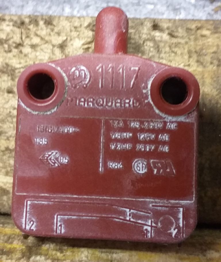
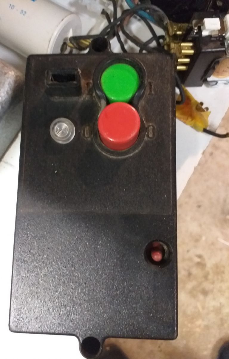
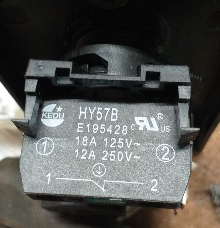
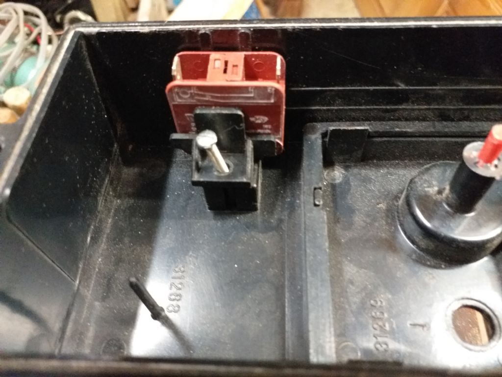
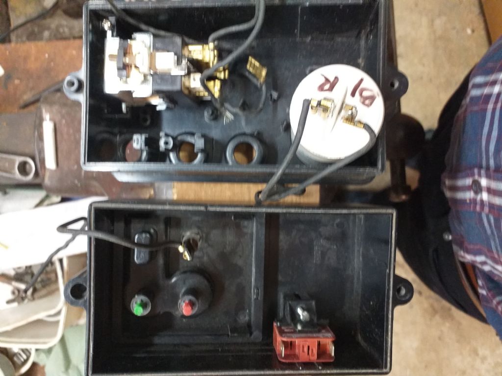
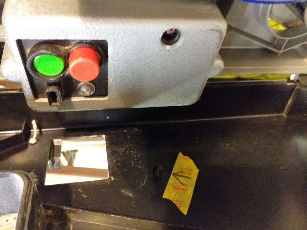
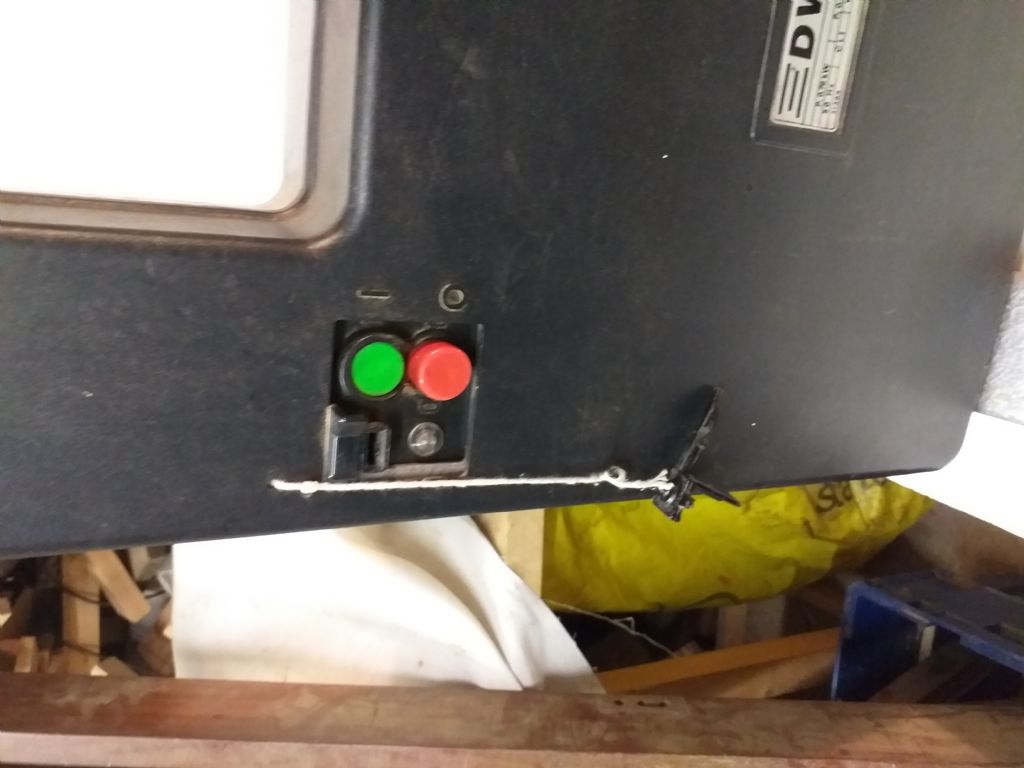
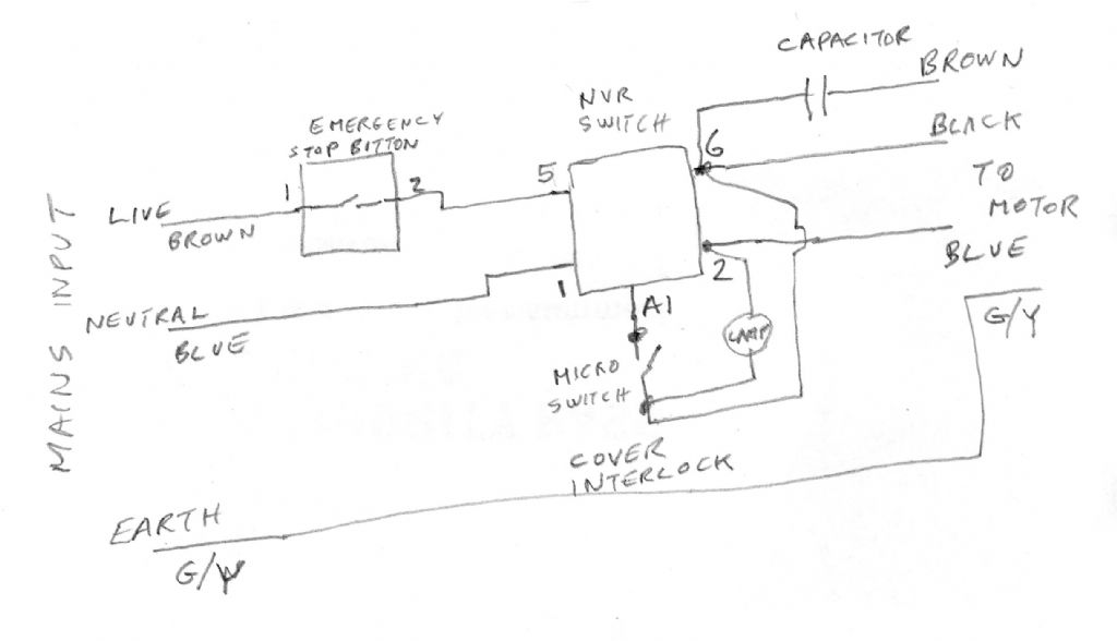
Blown band saw circuit.
Blown band saw circuit.
- This topic has 60 replies, 9 voices, and was last updated 15 October 2020 at 17:14 by
Marischal Ellis.
- Please log in to reply to this topic. Registering is free and easy using the links on the menu at the top of this page.
Latest Replies
Viewing 25 topics - 1 through 25 (of 25 total)
-
- Topic
- Voices
- Last Post
Viewing 25 topics - 1 through 25 (of 25 total)
Latest Issue
Newsletter Sign-up
Latest Replies
- What Did You Do Today 2025
- Amadeal AMABL210E Review – Any Requests?
- ML10 backgear
- Chucking Money Away!
- Boxford lathe & vertical mill VFD conversion help with start stop
- Speed camera
- Twin Engineering’s heavy mill/drill quill removal
- New member
- The Perpetual Demise of the Model engineer
- Colchester Chipmaster Clutch question


