Blown band saw circuit.

Advert

Blown band saw circuit.

Home Forums Electronics in the Workshop Blown band saw circuit.

Viewing 25 posts - 26 through 50 (of 61 total)
  • Author
    Posts
  • #493473
    Les Jones 1
    Participant
      @lesjones1

      I have just been reading through the thread again. I had misread the first post and thought that the motor ran when the start button was held pressed but you actually said when the TRIP SWITCH was held pressed. All I have said so far is not relevant. If you have to keep the trip switch pressed in then the motor is taking too much current or you have been supplied with the wrong current rating of trip switch. (You should never hold a trip switch in as it is designed to remove the supply id the load is taking too much current.) Sorry for my error in reading your first post.

      Les.

      Advert
      #493492
      Brian Morehen
      Participant
        @brianmorehen85290

        Have just read about your problems.The fact that you can hold the contactor in and your motor runs definatley sounds like the coil is faulty

        Good luck Brian Morehen

        #493556
        Marischal Ellis
        Participant
          @marischalellis28661

          Back home this afternoon and have the following to report. I am so sorry if I am misleading everyone.

          With everything as is, ie nothing disconnected or pressed in, I got the following. The digital meter reads 1. but will, when placed against terminals read various Ohms before very quickly reducing down to O. It moves very quickly so it is not easy to read the fractions to three places. If I connect the two probes together it will read 0 Ohms..

          Terminals 4 to 8 – 4.22 Ohms reducing to 0. Reading can fluctuate a bit but possibly down to my technique.

          3 to 7 – no reading. Meter did nothing.

          2 t ditto ditto

          1 to 5 ditto ditto

          Across the reset button, both in and out, nothing happened in terms of physical action, that I could feel, so no reading possible.

          With the coil pressed in.

          Terminal 4 to 8 4.2 or 3.7 Ohms. There was variations on the start of readings.

          3 to 7 no reading. Meter did nothing.

          2 to 6 ditto ditto

          1 to 5 ditto. ditto

          Over the capacitor terminals I got readings of 2.66 Ohms.

          Les, you noted a NVR switch may possibly be used. If this present stuff is all too mixed up, I would be happy to go down that route; all things being equal. Looking at my saw bench which has an NVR it seems OK with the reset button wired in but no allowance of a capacitor.

          I could possible separate the coil and contacts as there is very little to show connected between them, but I would need to be very careful of the return or hold back spring on the top, but cannot see where things would spill (or spring) out of.

          I have ordered a replacement reset button which should be here in a few days as the 'was new' switch is definitely not right. It is not functioning even as it did last time when I tried it. Hope I being more helpful this time around and my information is less misleading.

          Marsh

          #493595
          Les Jones 1
          Participant
            @lesjones1

            Hi Marsh,
            It looks like the "1" reading is your meters way of indicating over range. (Open circuit.) I now have confidence in the resistance readings in your last post. They seem to indicate that the schematic I drew is wrong. If it was correct then without the solenoid pressed in 4 to 8 should be open circuit (Your meter reading "1".) and with the solenoid pressed in it should have read 0 ohms.Can you confirm that it was the overload trip button that you had to hold pressed to get the motor to run after the initial fault ? (NOT the start button as originally thought.) Have you checked that the motor is free to turn by hand ? What is the mains voltage in your country ? (I am thinking that if it is 110 volts Then a overload trip for the 240 volt version may have been supplied. This would be about half the current rating required for the one for 110 volts. You do not need to worry about about the capacitor. It is wired the same way as it would have been wired if it was strapped to the motor. The NVR switch I linhed to is a 240 volt version but you may need a 110 volt version.

            Les.

            #493597
            Marischal Ellis
            Participant
              @marischalellis28661

              Hi Les

              The motor turns fine. When I Impressed the rest button which when held in let it all turn 'as normal' or at least it seemed like that. I pressed the reset button the motor turn quite OK it seemed. The reset switch was correct rating and so on. A 240 rating for the NVR and a 16 amp rating would be OK.

              M

              #493598
              Marischal Ellis
              Participant
                @marischalellis28661

                Hi Les

                The motor turns fine. When I Impressed the rest button which when held in let it all turn 'as normal' or at least it seemed like that. I pressed the reset button the motor turn quite OK it seemed. The reset switch was correct rating and so on. A 240 rating for the NVR and a 16 amp rating would be OK.

                M

                #493651
                Les Jones 1
                Participant
                  @lesjones1

                  I have now found the manual for this saw here
                  **LINK**

                  It includes a schematic but does not seem to be quite the same as I suspected. It does not show the item that Marsh calls a "Trip switch" which he shows directly in series with the input live feed. I had assumed that this was a thermal overload trip switch. The schematic does show a safety micro switch which only breaks the feed to the contactor coil. The manual also shows that there is a safety key which has to be inserted to start the saw. I am now wondering if the thing that Marsh calls a "trip switch" is this safety micro switch.

                  Marsh, Can you confirm that your saw does NOT have the key that is shown in the manual ? With the "trip switch" not connected can you measure the resistance between it's contacts with it not pressed and also with it pressed.

                  Les.

                  #493691
                  Marischal Ellis
                  Participant
                    @marischalellis28661

                    Morning Les

                    I looked for a manual years ago but couldn't find one and similarly a few weeks ago so wonderful you have found it. A big thank you. I have now printed it off.

                    I have looked at the elect diag. (top right hand) and they do seem to be a bit different. The safety micro switch looks to connected in another way but that may be convention. So the micro switch is the trip switch or the reset button it seems as I have called them. Looking at the diag. the micro switch (26) looks as if they are the same shape, etc.. The key is a manual plastic wedge key which when inserted or pushed in mechanically allows the start button to move in..

                    The readings for across the trip (micro) switch are as follows; button 'pressed in' the resistance goes to about 6.9 reducing to 0. For button 'not press' in there were no readings. The teleswitch is the contactors.

                    Thank you once again. The diag.is a big help. I hope this is helpful.

                    Yours Marsh

                    #493741
                    Marischal Ellis
                    Participant
                      @marischalellis28661

                      Hi

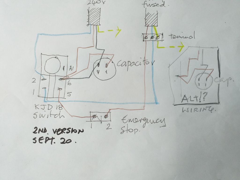
                      I have been thinking! ……….I have tried to do a new circuit using the same or similar switch as on my table saw. The reset button is at the bottom as saw and I have added a capacitor to suit band saw. Would possibly bring controls up to date and make them future proof a bit. Yours

                      saw wiring.jpg

                      #493742
                      Marischal Ellis
                      Participant
                        @marischalellis28661

                        I should have said wiring was so much easier when there was a red wire and a black wire. What could go wrong!

                        Yours

                        #493768
                        Les Jones 1
                        Participant
                          @lesjones1

                          From your test on the switch that you call a trip switch and DeWalt calls a safety switch it just seems to be a normally open push button switch. The way you show it connected in your first post it must be in the pressed position for the saw to work. Can you post a picture of the original switch that was saw when it failed showing any printing on it. From the description safety switch I am wondering if it could be an interlock switch to ensure the cover is closed for the saw to work. If this switch is intended to be pressed manually is the a label next to it ?
                          The KJD22 NVR switch should work but it does not have the key function.

                          Les.

                          #493847
                          Marischal Ellis
                          Participant
                            @marischalellis28661

                            HI

                            Yes it is the safety switch. The name trip switches must be from another earlier era.? I think it is an open press button. The writing on the switch is almost too small to see and the photo didn't work, so I have written it down. I am tidying up so must have thrown the old (original) switch out I am afraid. They were the same from a DeWalt replacement. I have another coming in the next day or so as it has been posted out. I don't think it is an interlock switch . No writing ever near it. Here is the very small writing on switch.

                            12A 125-250V AC

                            1/5HP 125 AC

                            1/2HP 250 AC

                            R 84

                            This is how it is written out. I will look further at the NVR switch (on my table ) similar to the one you suggested earlier just in case! A lot more wires on it than than I thought. With every best wish. Marsh

                            #493885
                            Les Jones 1
                            Participant
                              @lesjones1

                              With that micro switch connected as in the diagram in your first post or connected as in the drawing in the manual the motor can't run unless that switch is closed. (For it to be closed it must be pressed from the results of your test in your post at 12:20 on Sept 01.) Can you confirm that your diagram in your first post shows correctly hoe the micro switch is connected ? The KJD22 NVR that you showed in a previous post and the 4 pin version are available from this supplier.
                              **LINK**

                              Either version could be used with your band saw. According to the manual versions of your band saw for some countries do not have the micro switch fitted. This is probably to comply with the regulations for different countries.

                              Les.

                              #493920
                              Marischal Ellis
                              Participant
                                @marischalellis28661

                                Hi Les

                                It is or was wired as my diagram with the micro switch as shown. I suppose I don't really need the micro switch anyway if other countries don't call for it, and the white running light which didn't work previously as I only work on my own and don't need a visible warning of running. Perhaps I should think more seriously about a new switch but I will take you advice please. They don't cost too much. I will sleep on it tonight or am I being a bit slow here?. Thank you so much for what you are doing and more.

                                Marsh

                                #494065
                                Les Jones 1
                                Participant
                                  @lesjones1

                                  When you receive the second new micro switch test it with your meter BEFORE fitting it to the saw to see if the results are the same as you reported in your post at 12:20 on 01/09/20 for the first new switch. Do you have a way to measure the current taken by the motor ? I expect the running current to be about 5 amps but the starting current will probably be over 20 amps. (It would probable draw the starting current for less than a second.) If you do then I suggest connecting the motor directly to the mains with a fuse in the circuit. (If you are in the UK then the 13 am fuse in a 13 amp plug will serve the purpose.) The reason for this is that I suspect the motor may be drawing too much current which has damaged the NVR or the original trip switch. In one of your posts you said that the resistance across the capacitor terminals was 2.66 ohms. This is actually the resistance of the two motor windings in series. This value seems low for that size motor.

                                  Les.

                                  #494079
                                  Marischal Ellis
                                  Participant
                                    @marischalellis28661

                                    Hi Les

                                    I will check in the morning. I hoping the micro switch may come tomorrow or Saturday in the post. I have to omit I have ordered a new NVR start switch and it is the one you suggested (poss) would work a week or so ago. So may come in the coming week. Thank you for all your thoughts. Write tomorrow.

                                    Marsh

                                    #494668
                                    Marischal Ellis
                                    Participant
                                      @marischalellis28661

                                      All

                                      Switches arrived today in the post so will look at them and come back with something whither right or wrong. Thanks to everyone.

                                      Marsh

                                      I have sent a PM to you Les.

                                      #495027
                                      Marischal Ellis
                                      Participant
                                        @marischalellis28661

                                        Morning to All

                                        I have uploaded my idea of how to wire a KJD18 switch the use of which was suggested weeks ago and I missed it……..I have been rather slow on the uptake, my apologies. The switch arrived by post the other day.

                                        The live wire going via the NVR is I'm sure correct but on reflection the wires through the switch terminals, ie. for 1 and 5, the connections should be mirrored so 1 would be for the live from the NVR including t 'black connections' from the capacitor. Terminal 2 is connected to A1 so can be live when switched. A1 is a small terminal measuring 2.5mm (others are 6mm). I have not used A1………I don't know what it is for.

                                        I do hope this is correct or 'almost' correct and am happy for all comments please. I can then go and buy a few spade terminals. Thank you.

                                        Marsh

                                        KJD18 switch wiring.jpg

                                        #495036
                                        Les Jones 1
                                        Participant
                                          @lesjones1

                                          Hi Marsh,
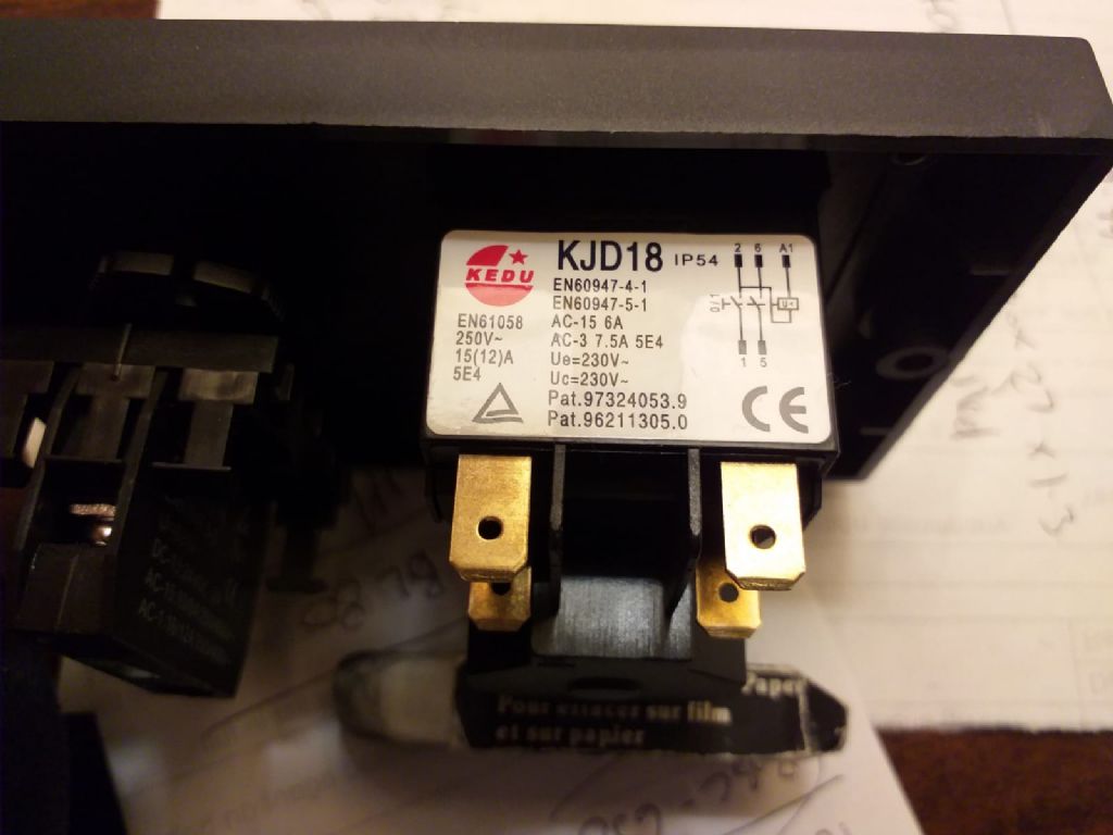
                                          You still seem to be confused. The KJD18 IS an NVR. (No volt release switch. This is to prevent the saw from starting when the mains is restored after an interruption to the mains supply.) The A1 terminal is one end of the holding (Or maintainer.) coil. This coil is fed from the NVR's output to hold it closed after the start button has been pressed and released. The thing you have labelled "NVR" I think is the item that there is confusion about, (The thing that you called a trip.) (Which we all assumed was a thermal overload to protect the motor but seems to be called a micro switch by DeWalt.) To avoid risking destroying the new NVR if it was the motor that caused the original fault I suggest Connecting the motor directly to the mains with the belt removed from the speed change pulleys and monitoring the current it is taking. This is relying on the 13 amp fuse in the plug to blow if the motor is taking a much higher current than it should. You need to test the second new thing that you called a trip with your meter to see if it behaves like a thermal cut out or a NO micro switch. You also need to show a picture of the diagram on your KJD18 as the connection numbering seems to vary on information I have found online.

                                          Les.

                                          #500332
                                          Marischal Ellis
                                          Participant
                                            @marischalellis28661

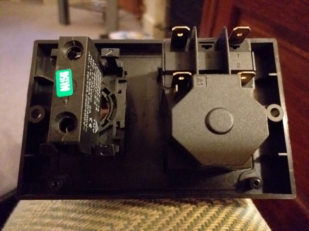
                                            20201005_110931 (2).jpg

                                            swtgback.jpg

                                            swtdiag.jpg

                                            Dear All

                                            My brains went AWOL a few weeks ago but seem to returning albeit slowly this week. They started back slowly and softly at the weekend.

                                            I have at last been able to give more thought to my previous misleading public ideas and include views of the back of the new switch, the diagram on the back, and my idea of wiring the switch taken from you tube and so on. My revised alternative is now shown to the right of the diagram and may actually be alright!

                                            If the switch is too big a capacity at 18 amps I can use it on another more simple higher rated machine with a red and a black wire! Les did suggest a smaller one of 12 amps.(I will double check back at replies/comments). I could just order overnight the smaller one…..just to get it done as my brains return so that I can mount in a suitable way on the machine.

                                            Thank you to everyone after so long a gap. Your thoughts have been such a support.

                                            M

                                            #500333
                                            Marischal Ellis
                                            Participant
                                              @marischalellis28661

                                              Again……………..The switch may be 15 amp rating not 18 which is somewhat smaller than I thought. Sorry for the misleading info once again. M

                                              #500347
                                              SillyOldDuffer
                                              Moderator
                                                @sillyoldduffer
                                                Posted by Marischal Ellis on 09/10/2020 11:51:25:

                                                Again……………..The switch may be 15 amp rating not 18 which is somewhat smaller than I thought. Sorry for the misleading info once again. M

                                                The switch isn't 15A either. The markings refer to Utilisation Categories, ie the rating depends on the type of load.

                                                AC15 is an AC electromagnetic load, for which the switch is rated at 6A.

                                                AC3 is a squirrel cage motor load, for which the switch is rated 7.5A

                                                Basically, it's OK for all motors up to about 1400 Watts input, and some types of motor up to about 1700W. Should be OK unless the machine

                                                Les Jones' post of 10/9 still seems valid.

                                                Single phase motors aren't my thing, but I think your circuit must be wrong because both sides of the capacitor are connected to pin 6 on the switch. It doesn't do anything. Also, A1 should be connected to the output side of switch, 6.

                                                Help! Motor expert needed!

                                                Dave

                                                #500374
                                                Les Jones 1
                                                Participant
                                                  @lesjones1

                                                  I agree with Dave's comments. I am not going to draw a wiring diagram for you until we sort out the function of the thing you called a trip and DeWalt call a micro switch. I suspect that the item to the left of the KJD18 (NVR switch) is a emergency stop button. Can you post a picture of the front of the panel that it is on and also the side of this item so we can read the ratings ? (This is so I can decide between wiring it to break the full load or just the feed to the coil on the NVR switch.) Can you also measure the resistance between the connections second new micro switch both with it pressed and with it not pressed ? Can you also post a picture of where this switch is mounted so we can see if it is some kind of safety interlock ?

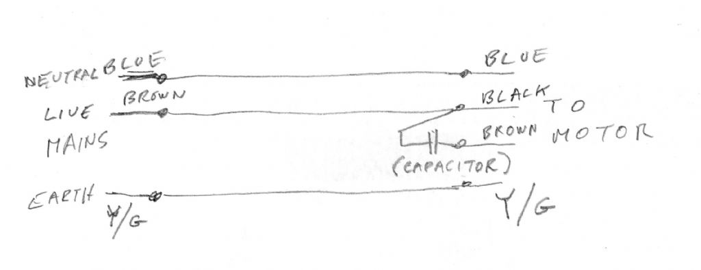
                                                  This is how to connect the motor directly to the mains to confirm that it is not drawing a very high current as I suggested in my post on September 10th. (This is to avoid damaging the new NVR switch if the original fault was caused by the motor.)

                                                  091020.jpg

                                                  Les.

                                                  #500591
                                                  Marischal Ellis
                                                  Participant
                                                    @marischalellis28661

                                                    Evening All

                                                    I have been checking this for most of the afternoon by going over the list and will report tomorrow how I got on. I had with the temp.rewire, the motor running but I need to check my multi-meter, as it looks as if it only does DC current with no mention of AC in the little booklet. So not done the current check yet but it sounded like it did before when running if that means anything!

                                                    Stay safe. M

                                                    #500687
                                                    Les Jones 1
                                                    Participant
                                                      @lesjones1

                                                      It looks like the motor is probably OK. Even if your mutlimeter has an AC current range it will probably be 10 amps maximum and the motor will take more than this when starting. This test was to ensure that the motor did not take a VERY large current that could destroy the new NVR switch. As it did not blow the fuse in the plug it is unlikely to damage the new NVR switch. We now just need to establish the exact purpose of the thing that you called a trip and DeWalt call a micro switch. It is a pity that you have disposed of the original item before we could establish if it was a thermal overload trip or just a NO micro switch.

                                                      Les.

                                                    Viewing 25 posts - 26 through 50 (of 61 total)
                                                    • Please log in to reply to this topic. Registering is free and easy using the links on the menu at the top of this page.

                                                    Advert

                                                    Latest Replies

                                                    Viewing 25 topics - 1 through 25 (of 25 total)
                                                    Viewing 25 topics - 1 through 25 (of 25 total)

                                                    View full reply list.

                                                    Advert

                                                    Newsletter Sign-up