Many thanks Baz,
3 questions please:
1 The valve chest contains 2 valves, one driven off the piston rod and one ( the shuttle valve ) which appears to be self propelled using pressure from the ports.
On the steam chest drawing ( Item 2) , looking at the side elevation , the piston rod driven valve spindle is 0.165 from the cylinder face. But I cant see a dimension for the 0.156 diameter shuttle passage/hole from the cylinder face ? Is it the same as the other valve i.e. 0.165 centre from the cyl face – i.e. both valves the same centre line distance from the cyl face , or something different ?
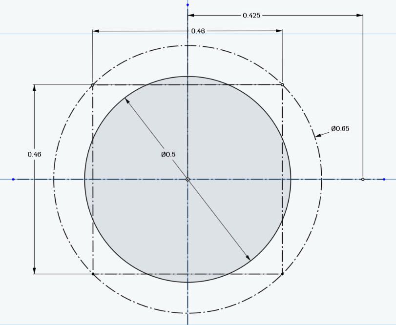
2 Also on the cylinder (item 1) end view, for the end cap bolt pattern where it says 'copy the bolt pattern from item 5' , these undimensioned bolt patterns on the cylinder do not look the same as the dimensioned ones item 5, which are a simple 0.5" square ? On the cylinder they are not a square , one side appearing wider. I am very aware of the close proximity of the steam chest holding down bolts in this area.
3 How closely do you follow the depth of the 10BA holding down threads on the plan? They seem extremely shallow, the 0.075 cylinder end cap and valve chest holding down bolts for example.
Thanks in advance
Edited By GrahamS on 18/07/2023 17:18:53
Edited By GrahamS on 18/07/2023 17:19:33
Edited By GrahamS on 18/07/2023 17:20:21
GrahamS.


