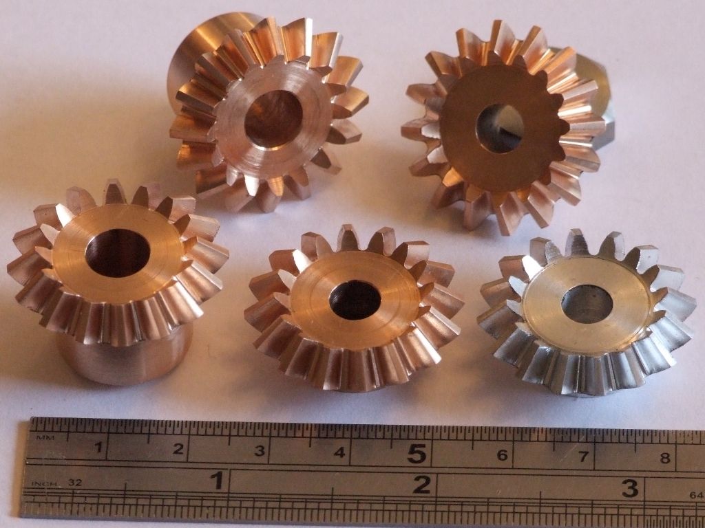
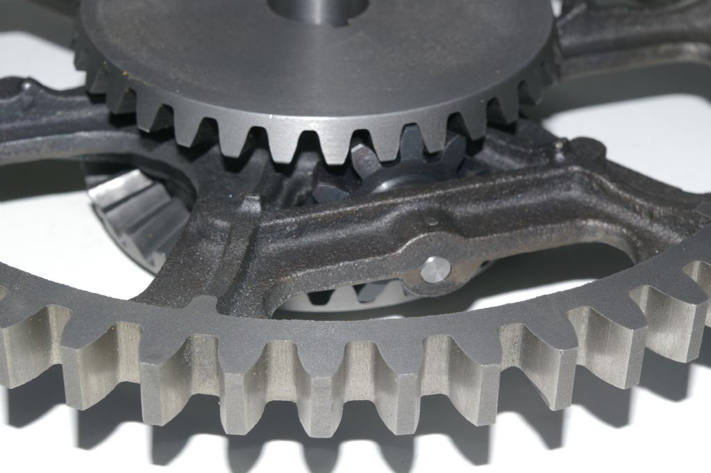
Bevel gears again
Bevel gears again
- This topic has 23 replies, 5 voices, and was last updated 28 April 2019 at 18:08 by
Dave Shield 1.
Viewing 24 posts - 1 through 24 (of 24 total)
Viewing 24 posts - 1 through 24 (of 24 total)
- Please log in to reply to this topic. Registering is free and easy using the links on the menu at the top of this page.
Latest Replies
Viewing 25 topics - 1 through 25 (of 25 total)
-
- Topic
- Voices
- Last Post
Viewing 25 topics - 1 through 25 (of 25 total)
Latest Issue
Newsletter Sign-up
Latest Replies
- Scam email
- What size gear cutter for gear
- bolts harness and head shearing?
- FreeCAD v1.0 tutorials
- 3D Filament Printer Upgrade
- 3 1/2” gauge diesel loco?
- Myford Super-7 chuck – unacceptable run-out??
- Adaptation of the Proxxon Milling machine
- S&B Sabel lathe quick change tool post
- Stuart Twin Victoria (Princess Royal) Mill Engine


