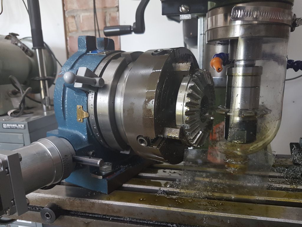
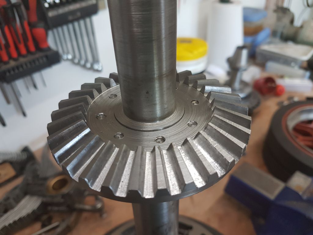
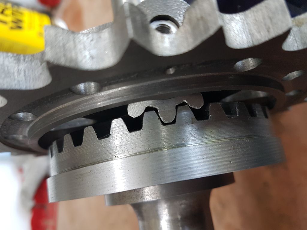
To set the scene there are two basic ways of cutting bevel gears on a manual mill. Normal straight tooth bevel gears are designed using the DP at the outer face of the gear. Since the tooth form decreases towards the centre of the gear a normal involute cutter of the correct tooth form will be too wide to go through the inner tooth space. Special involute gear cutters, stamped "BEVEL", could be used. These had the correct tooth form for the DP at the outer edge, but were thin enough to go through the small end. These cutters do not seem to be available now.
The other method is the parallel depth form. These are designed using the DP at the inner face of the gear, and hence standard involute cutters can be used.
From what you say I assume that the differential bevels are parallel depth. I agree with the PCD calculation for the crown wheel. For 'proper' bevel gears the equivalent number of teeth used to determine the cutter number is the actual number of teeth divided by the cosine of the pitch cone angle. Thus we get the equivalent number of teeth as 94.8 for the crown wheel and 10.5 for the pinion.
However, the calculation for parallel depth gears seems to use a different method, as described in the book you link to. However, I get the same answers as before. The key is that the angle used for the parallel depth method is not the pitch cone angle, but 90° minus the said angle. I would ignore the reference to using the midpoint of the face width. Parallel depth bevels are an approximation, so I see no need to fine tune the cutter number.
It is perfectly acceptable to use a pressure angle of 14½° for all the gears. In all probability that is what the prototype would have used, as it is the older standard.
NB: I found the book linked to so useful I bought a paper copy. I first used it 40+ years ago to make some bevel gears using the BEVEL style involute cutters.
Andrew
Norman Rogers.


