Between Centres Boring Bars

Advert

Between Centres Boring Bars

Home Forums Workshop Tools and Tooling Between Centres Boring Bars

Viewing 10 posts - 1 through 10 (of 10 total)
  • Author
    Posts
  • #516428
    Greensands
    Participant
      @greensands

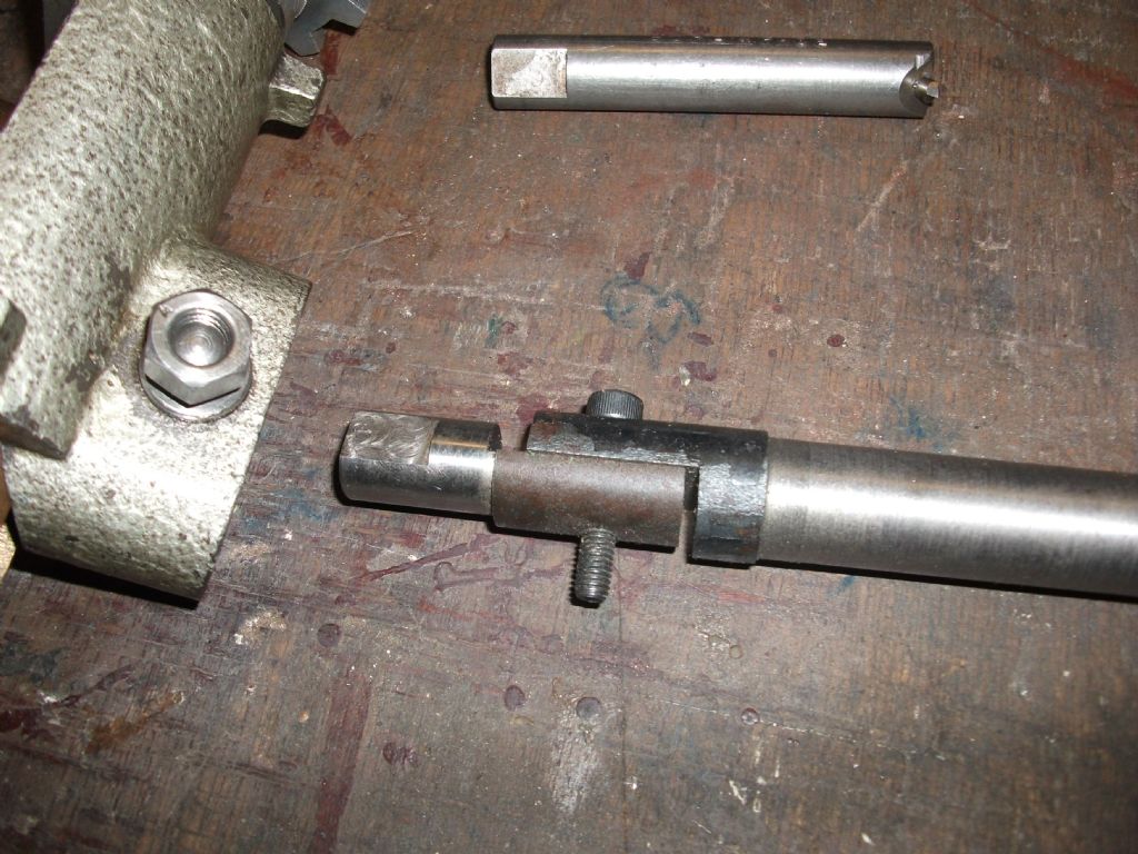
      Hi – I have in my collection of tools a couple of between centres boring bars, one of 7/8" dia fitted with a 1/4" cutter the other 5/8" dia with a 3/16" cutter, the difference being that the larger bar with the tool set at an angle is fitted with a fine thread adjustment. In the case of the smaller bar the lack of such a feature is a distinct disadvantage and I have often wondered how things could be improved. One obvious thought is to tap out 2BA for a short length behind the tool but at a 90deg angle and a 5/8" dia bar there is not too much meat to play with. Are there perhaps other ways to include some sort of fine feed arrangement to take the hit and miss out of the equation. All suggestions would be most welcomed.img_9710.jpg

      Advert
      #20084
      Greensands
      Participant
        @greensands

        Fine Feed Adjustment for a Between Centres Boring Bar

        #516430
        JasonB
        Moderator
          @jasonb

          make an adjuster like these

          #516435
          DC31k
          Participant
            @dc31k

            The one Jason suggested is very nice.

            If you search 'boring bar micrometer' and look at images, some of the results will give you some ideas. Any that include 'Van Norman' are not what you are looking for – it is the ones that look like a standard micrometer with the fixed anvil replaced with a vee block.

            A vee-block with a micrometer barrel strapped perpendicular to the vertices of the two vees would work. Replace vee block with an old centre-square body and add micrometer.

            Grind a notch in the cutting bit diametrically opposite the securing screw. Use a second screw with a tapered end engaging in the notch to advance the bit. Very limited range of movement with this though.

            Use a normal micrometer across bit and bar after doing an initial cut and measure. If diameter of cutting bit is so large that micrometer anvil falls into the hole, use a gauge block to span the hole. This does mean you have to shorten the butt end of the cutting bit shown in the photo.

            See also:

            https://www.model-engineer.co.uk/forums/postings.asp?th=130528

            https://bbs.homeshopmachinist.net/forum/general/37455-boring-bar#post721214

            OK, found it. Search for Moore & Wright 462.


            Edited By DC31k on 31/12/2020 10:38:52

            #516437
            John P
            Participant
              @johnp77052

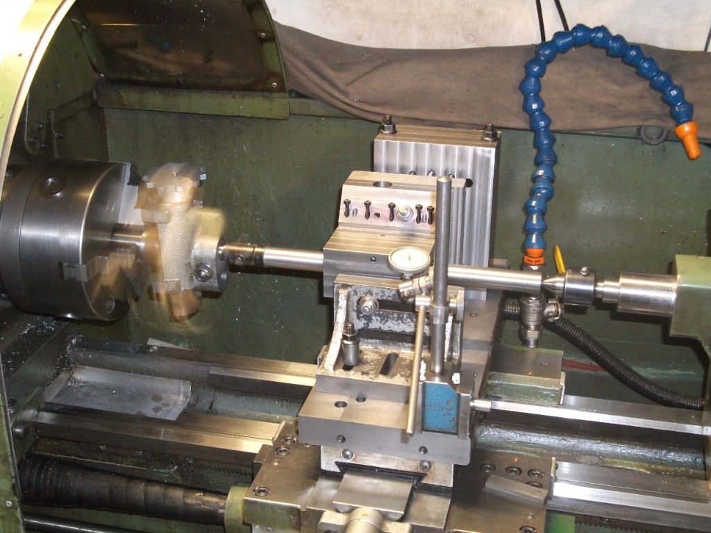
              This combination of a boring bar and boring head works well ,with the cutter at half way along the bar .001 adjustment on the boring head = .0005 at the toolbit.. The normal boring tool fitted in the boring head is replaced with an articulated joint to connect to the boring bar ,you can just about see the Dore boring head and connector in this photo.

              Johnboring bar.jpg

              #516440
              DC31k
              Participant
                @dc31k
                Posted by John Pace on 31/12/2020 10:37:26:

                This combination of a boring bar and boring head works well

                That is very good. Is the connector providing the drive in lieu of a dog?

                I have seen boring heads used horizontally and stationary in the tailstock for taper turning (saves offsetting and resetting the tailstock).

                I think the same arrangement would work for between centres boring (i.e. it does not matter which end of the bar the boring head is). Is that correct?

                #516442
                ega
                Participant
                  @ega

                  Greensands:

                  Your bars resemble those described by GHT in his ME Workshop Manual so I assume you have considered the excellent advice there?

                  #516506
                  Greensands
                  Participant
                    @greensands

                    Hi everyonel – Thanks for all the useful help provided. Had not thought of using a boring head in a between-centres application but can see how it could work. EGA, Yes I am pretty sure that the larger bar is a Geo Thomas design. Think my next step will now be to make up a Hemmingway type fine feed adjuster.

                    #516670
                    John P
                    Participant
                      @johnp77052

                      Posted by DC31k 31/12/2020 10:49:04

                      That is very good. Is the connector providing the drive in lieu of a dog?

                      I have seen boring heads used horizontally and stationary in the tailstock for taper turning (saves offsetting
                      and resetting the tailstock).

                      I think the same arrangement would work for between centres boring (i.e. it does not matter which end of
                      the bar the boring head is). Is that correct?

                      Hi DC31k

                      The Dore boring head is made to fit on a Myford nose in the previous photo
                      this is mounted on an arbor held in the Warco chuck ,the boring head
                      provides the drive for the boring bar via the articulated joint is seen in this photo.
                      It is important that the joint in in line with the slides of the boring head,as the
                      boring head is adjusted the boring bar runs eccentrically to increase the cut depth.
                      The boring head can only be used at the headstock end and the tailstock
                      providing the support for the other end of the boring bar.
                      This was not my own idea but was seen in MEW issue 168
                      page 56 by Ted Barclay in which showed an amalgamation of a between
                      centres boring bar and boring head .

                      Johnboring bar.jpg

                      #516691
                      ega
                      Participant
                        @ega
                        Posted by Greensands on 31/12/2020 16:06:33:

                        Hi everyonel – Thanks for all the useful help provided. Had not thought of using a boring head in a between-centres application but can see how it could work. EGA, Yes I am pretty sure that the larger bar is a Geo Thomas design. Think my next step will now be to make up a Hemmingway type fine feed adjuster.

                        More power to your elbow but can you not just mic across the cutter and bar as suggested by GHT?

                      Viewing 10 posts - 1 through 10 (of 10 total)
                      • Please log in to reply to this topic. Registering is free and easy using the links on the menu at the top of this page.

                      Advert

                      Latest Replies

                      Viewing 25 topics - 1 through 25 (of 25 total)
                      Viewing 25 topics - 1 through 25 (of 25 total)

                      View full reply list.

                      Advert