Best approch for securing a brass bush

Advert

Best approch for securing a brass bush

Home Forums Workshop Techniques Best approch for securing a brass bush

Viewing 9 posts - 1 through 9 (of 9 total)
  • Author
    Posts
  • #66355
    Nicholas Farr
    Participant
      @nicholasfarr14254
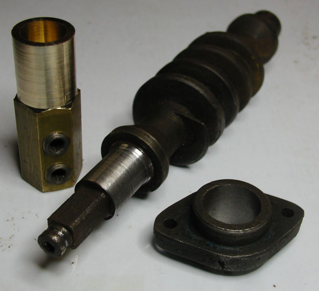
      Hi, below is a picture of a worm from a hand operated winch. The front journal and its bearing were worn and corroded to a sloppy fit, so I’ve turned down the journal to reach good metal and to be round and the bearing likewise. A piece of scrap hard brass has been preped for a bush.

       
      Now while in the past when working at my old employment I have fitted many brass bushes of sizes in the range of 2″ to 6″ in steel with a 100 ton press at my dsposal, I haven’t really had to make and tackle anything this small and delicate. The bearing is made of cast iron and the bore is now appox 22mm and about 22mm long, the round projection is about 8mm high with a wall thickness of 4mm, and the journal on the worm is now approx 18.5mm.
       
      My question is what would be the best way of securing the brass bush in the bearing? Would it be wise to try and make it a press fit and if so what size over the bore should I aim for?
       
      The other methods may be Loctite or silver soldering. The main thing is, I do not want to bust the bearing casting.
       
      Any suggestions are welcome.
       

      Thanks in advance.

       
      Regards Nick.
      Advert
      #15514
      Nicholas Farr
      Participant
        @nicholasfarr14254
        #66359
        Steve Garnett
        Participant
          @stevegarnett62550

          For myself, I’d make it an easy sliding fit, and use loctite bearing retention compound. This way, if the sleeve fails, all you have to do is heat it to about 150 degrees or thereabouts, and it will come out again. If you really want to press-fit it, then the oversize probably needs to be around a thou, and I’d also heat the bearing before inserting it. If you really don’t want it to move, then rough the sleeve surface as well.

          Edited By Steve Garnett on 31/03/2011 22:40:49

          #66365
          Clive Hartland
          Participant
            @clivehartland94829
            I would first cut and oil groove in the sleeve and then using Loctite fit the sleeve in a ‘Push fit’ condition. Thoroughly degrease before assembly.
            After it is in place I would then drill into the oil groove to be able to oil the brg.
            A worm drive has a heavy load to carry and would benifit from lubrication.
            Maybe why it failed in the first place!
             
            Clive
             
            #66368
            Ian S C
            Participant
              @iansc
              Steve, it would be better to put the bush in the freezer rather than heat it, if the housing could be heated thats OK , you want the bush smaller, and or the housing bigger.
              The simple way, Loctite. Ian S C
              #66369
              Steve Garnett
              Participant
                @stevegarnett62550

                Do both – one in the freezer, the other heated?

                #66374
                KWIL
                Participant
                  @kwil

                  In the “old days” I always inserted new valve guides into IC engines by freezing the guide and merely sliding into place. You had to have a stop set up otherwise by the time it was in the correct place it had warmed enough to “fix it”. That meant drilling it out!!

                  #66379
                  Steve Garnett
                  Participant
                    @stevegarnett62550
                    FWIW, the reasons that I said in the first place to heat the outer bearing were a) it’s off the fitting, and not too large, b) even though I accept that brass has a slightly higher coefficient of expansion, with the best will in the world, you are only going to achieve about a 40 degree change of temperature in the brass in the freezer, but it would be relatively easy to achieve a greater difference in the iron (even in boiling water), which would promptly expand the brass into contact with it, and they’d both contract together. The other way around, you have to wait for the brass to warm up before significant contact is made. So under these particular circumstances, I’d expand the iron.
                     
                    I do realise though that in a normal-size IC engine, this is a bit impractical…

                    Edited By Steve Garnett on 01/04/2011 17:10:15

                    #66386
                    Nicholas Farr
                    Participant
                      @nicholasfarr14254
                      Hi gentlemen, first of all thanks for the advice regarding the best method for securing my bush.

                       
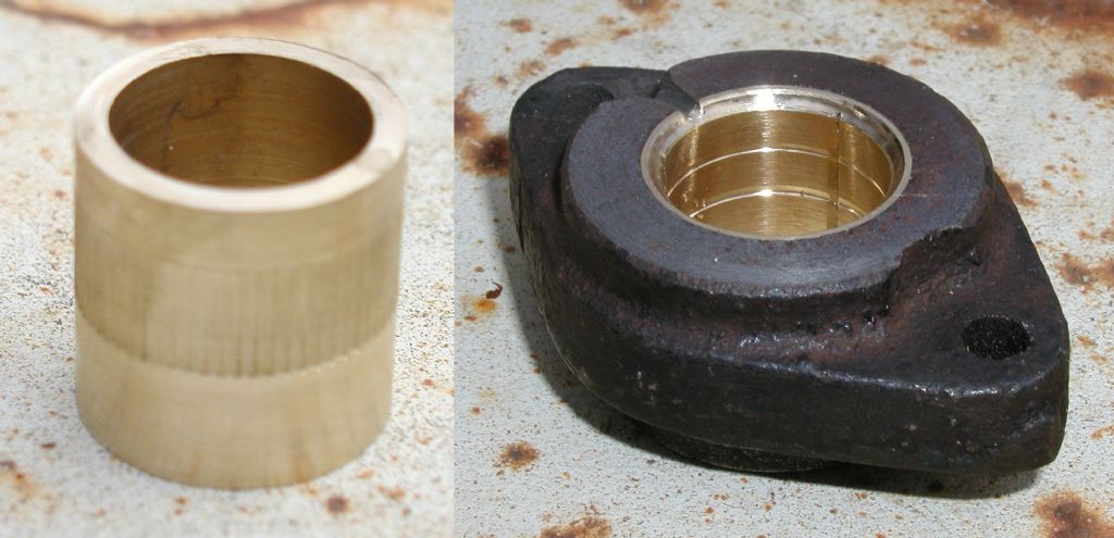
                      Following Steve and Clive’s advice, I decided to loctite the bush in. I kind of combined both your suggestions with my own idea as well, in that I made the bush to a push fit, but then releaved the end that would align with the 8mm long projection to a close slide fit. and the section that fell in line with the two holed fixing flange I knurled lightly with fine striaght pattern wheels, this made it about a thou and a half in that area bigger than the bore. It was then cleaned with loctite spray cleaner and 638 was applyed at the projection end of the bearing bore and on the knurled part of the bush. The bush was then pushed in on my fly press and went in with what I consider a nice feel and no fractures occured. It was then left to cure for a couple of hours or so and was then bored out to fit the newly turned part of the worm. A couple of grooves were then cut into the bore to help distrubute lubricant along with a couple of grooves long ways. (See pic below)
                       

                      Clive, I considered an oil hole, but when it is assembled there would be no practical way of useing it, but I did disc cut a small groove across the face where oil could be squirted towards that area and some would find its way in (hopefully)

                       
                      Graham, In the first picture it shows the end away from the the worm flange and the proportions are a little deceaving, the above picture shows the end that it fits up to and there is a thrust washer inbetween and covers virtualy all the area that can be seen, but suprisingly there is no wear in the end float that could not be tolerated.
                       
                      This winch spent all its life out in all weathers with an 18Kw submersable dewatering pump hanging on it for many years untill it was condemmed by the insurance company for its condition and the fact the load rating sticker was missing. As it was scraped, a few pretty please words to my department head secured it for me as long as I removed it from the works forthwith. Its been kicking about in my garage several years waiting to be fixed, and will now be an attachment for my rebuilt car trailer.
                       
                      Once again thanks for all your advice.
                       
                      Regards Nick.

                      Edited By Nicholas Farr on 01/04/2011 20:50:54

                    Viewing 9 posts - 1 through 9 (of 9 total)
                    • Please log in to reply to this topic. Registering is free and easy using the links on the menu at the top of this page.

                    Advert

                    Latest Replies

                    Home Forums Workshop Techniques Topics

                    Viewing 25 topics - 1 through 25 (of 25 total)
                    Viewing 25 topics - 1 through 25 (of 25 total)

                    View full reply list.

                    Advert

                    Newsletter Sign-up