Hi all,
I set about trying to finish the engine yesterday and hopefully give it a test run.
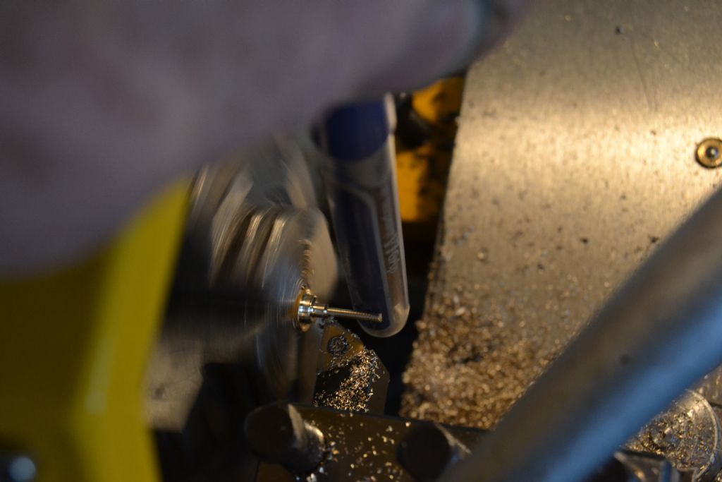
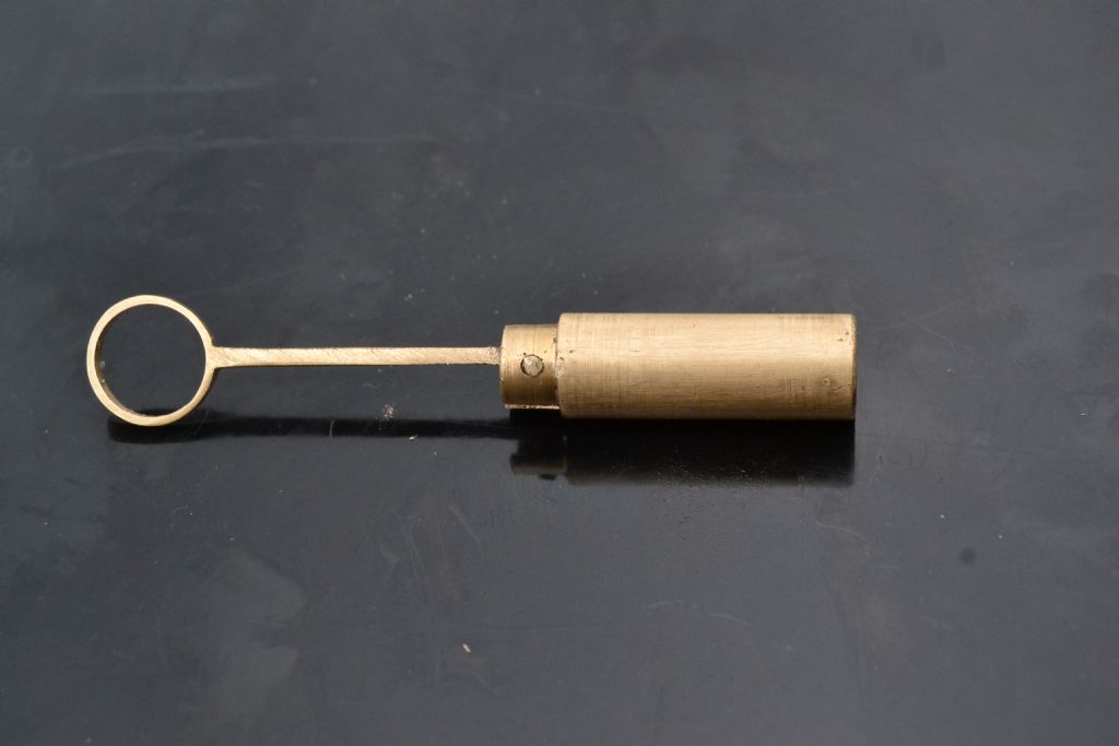
Firstly I needed a better wrist pin than the temporary staple I was using. It involve turning a piece of brass rod down to about 1.5mm but with care that shouldn't be a problem.
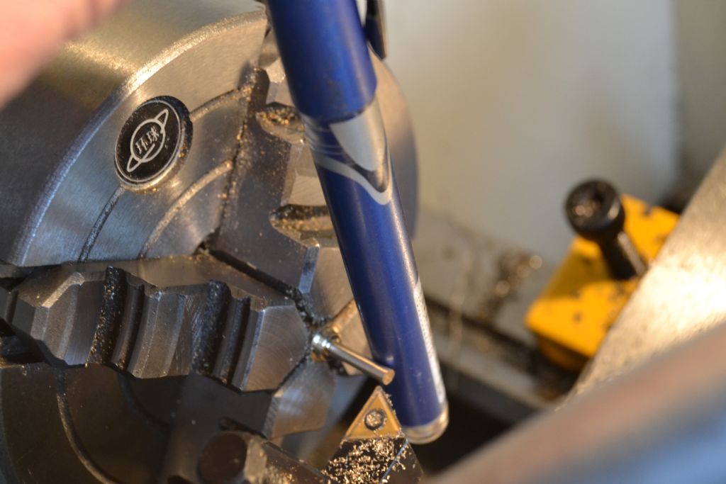
At about 2mm the rod is starting to flex and the tapered cut I'm getting becomes apparent, thankfully the Poundshop sell these blue travelling steadies at 6 for a quid in the biro section

The taper seems to have gone

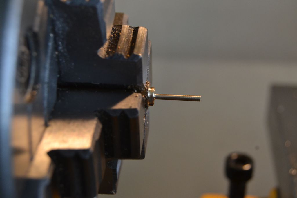
Eventually I arrive at this,

1.55mm and just right.


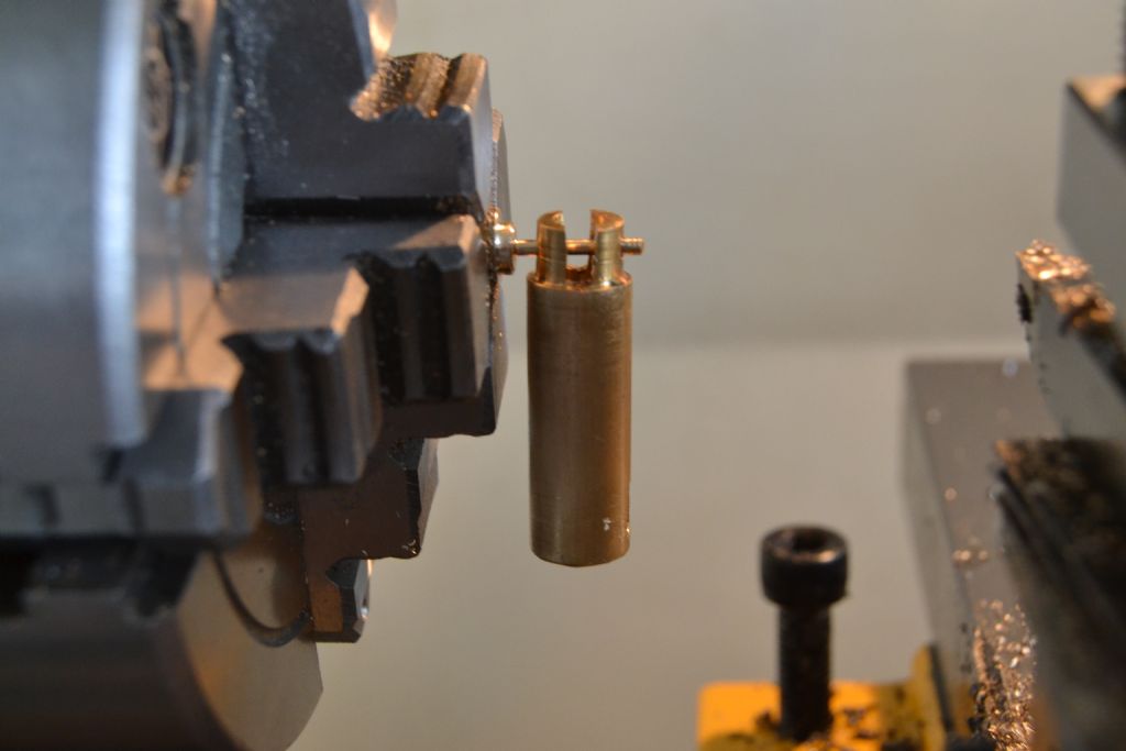
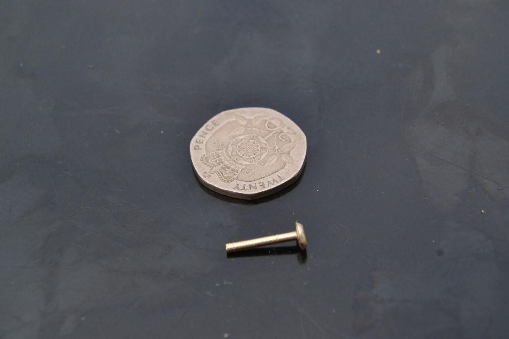
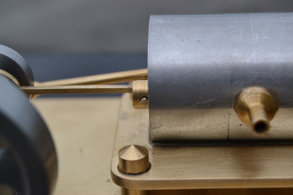
Cut to length and the end lightly peined over all seems ok.

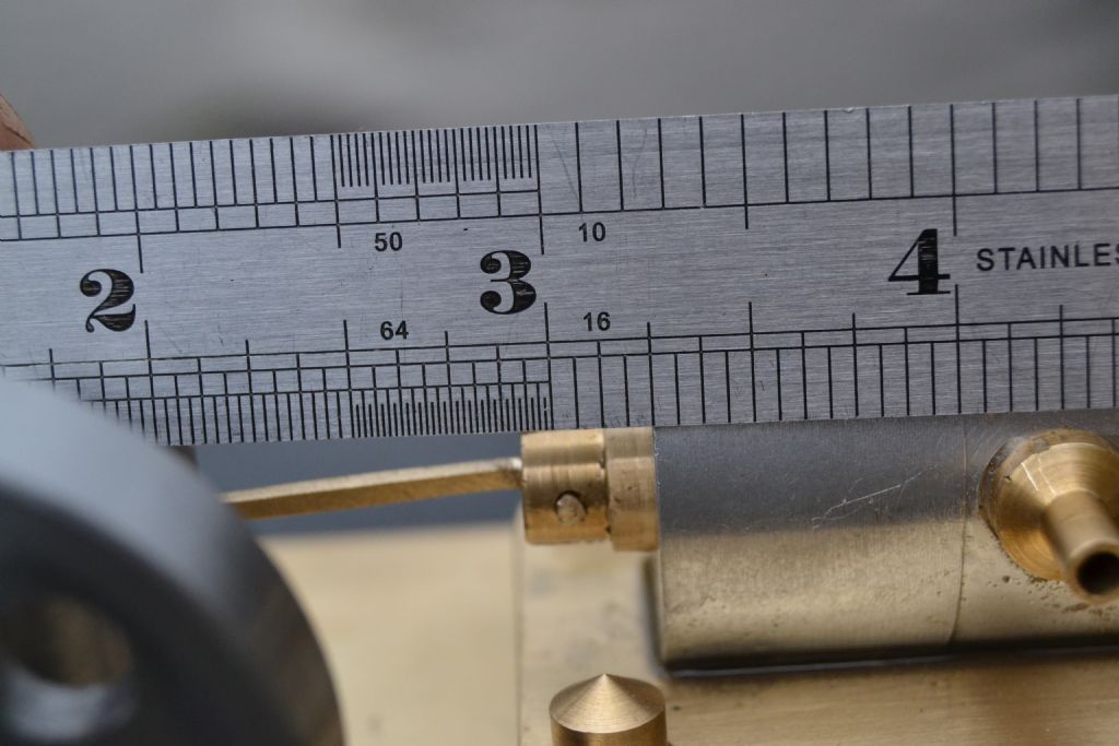
The wrist pin needed to be just short of the end of the cylinder at maximum travel and have a 3/16 stroke, so I'm hoping I've achieved that with sufficient accuracy.


With the wrist pin done all that's needed now is a few spacers for the axle and then a test run.
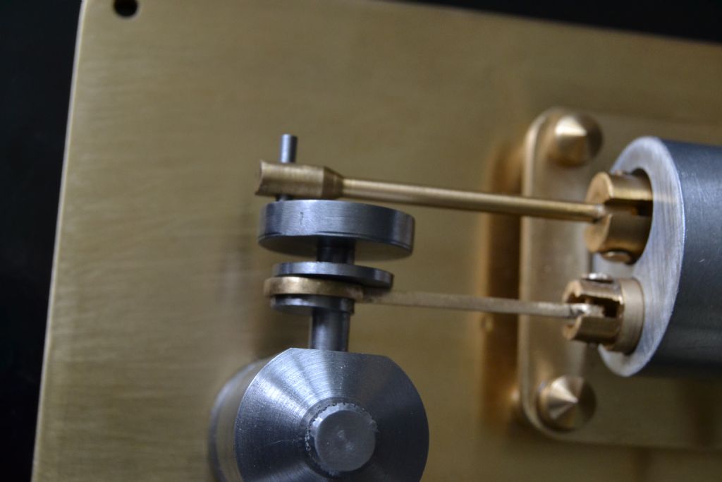
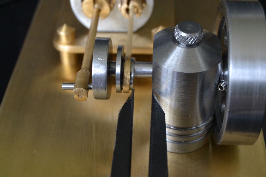
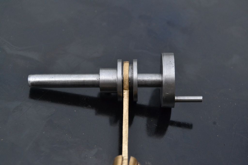
I'm satisfied this is the alignment needed, so I need a spacer with a disc to keep the eccentric in place then possibly another one between the eccentric and crank and finally a small one behind the fly wheel may help.

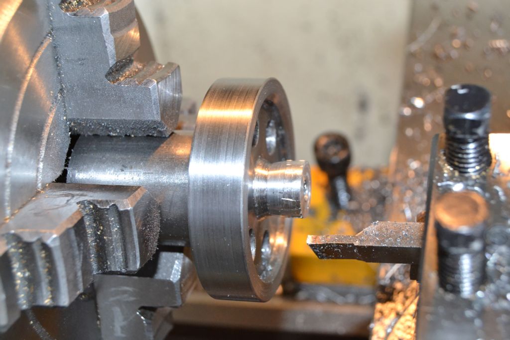
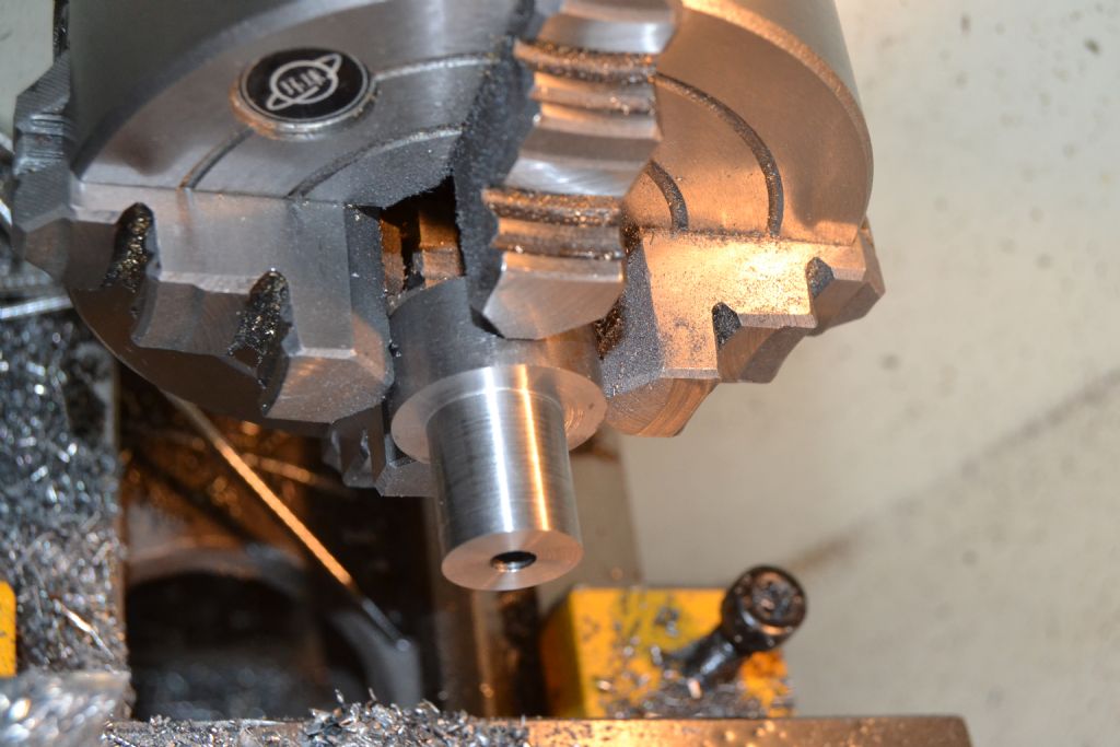
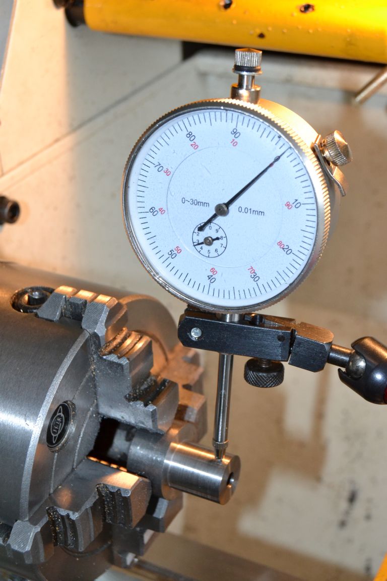
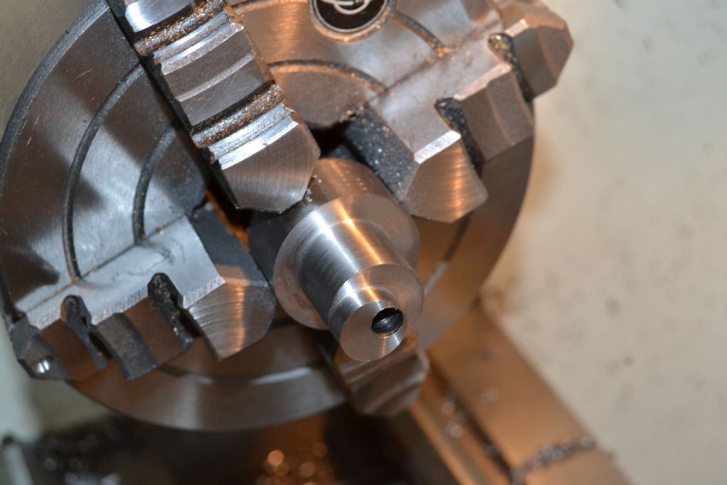
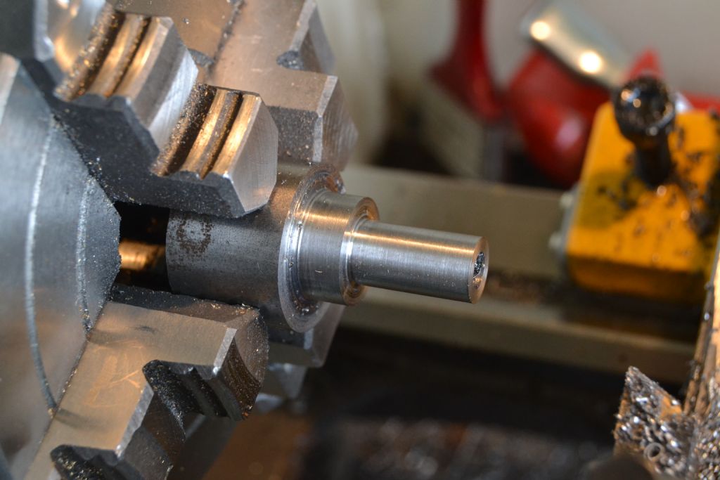
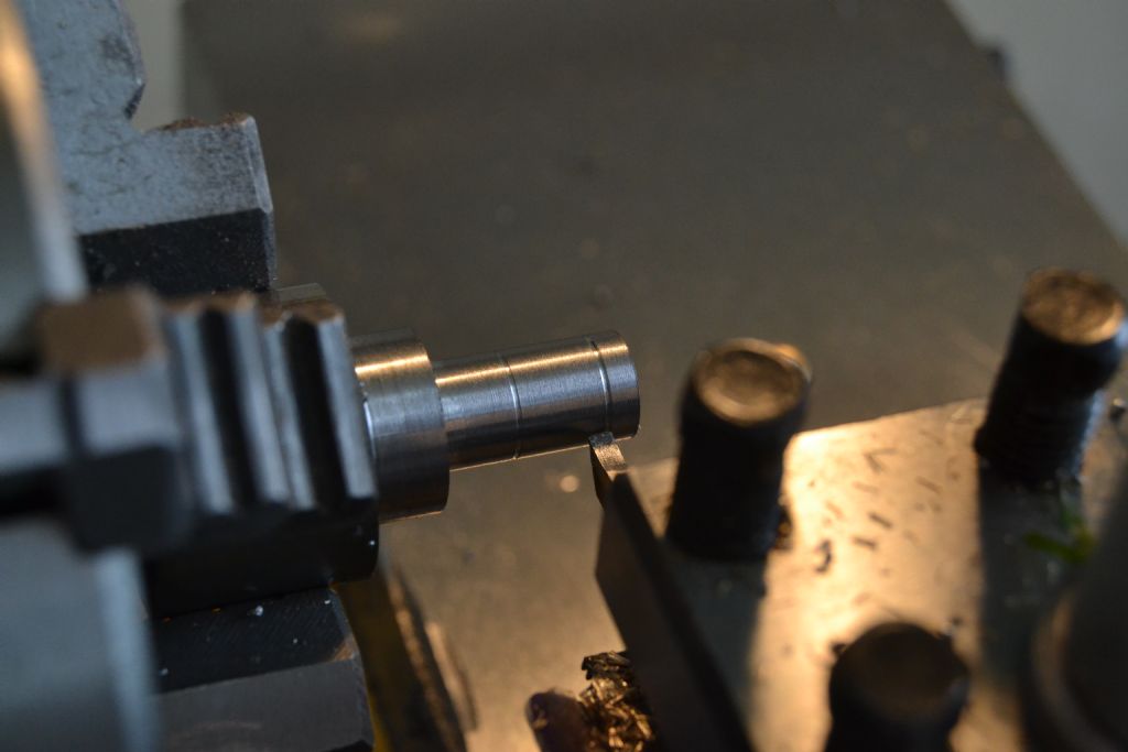
A steel bar turned at one end to 16mm (the eccentric retaining disc), reduced down to a smaller diameter for the spacers and drilled to accept the axle.

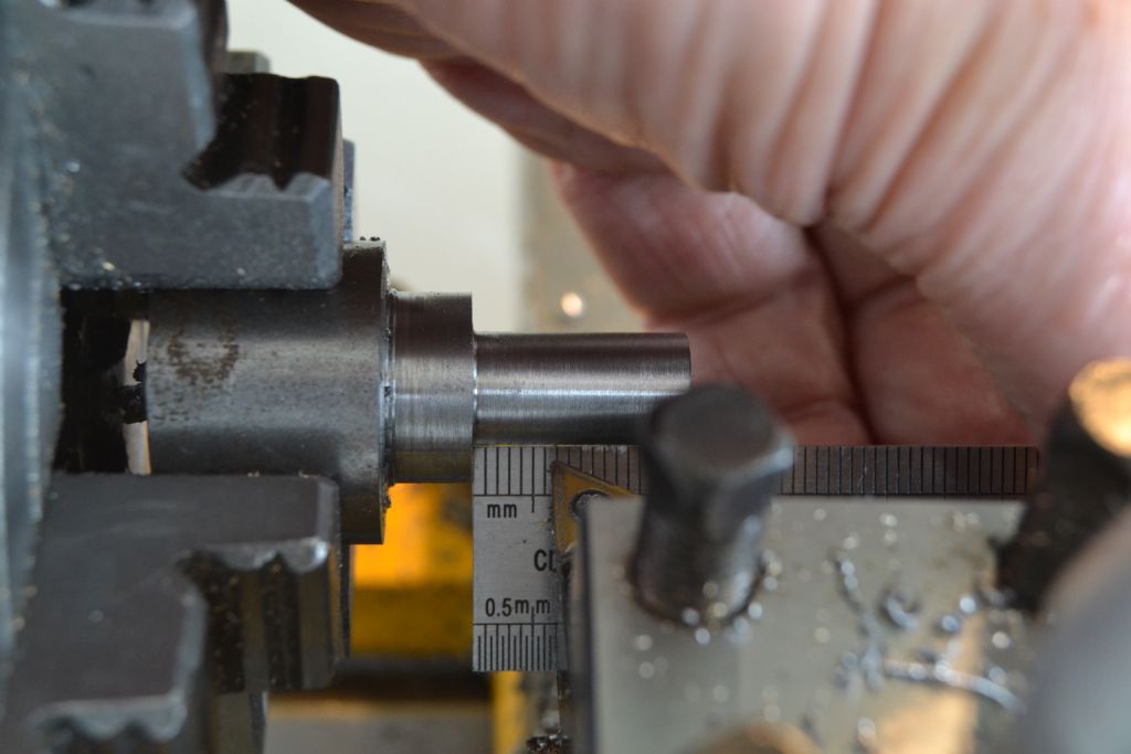
A bit of a makeshift idea but I reckon the eccentric disc/spacer need to be 6.5mm

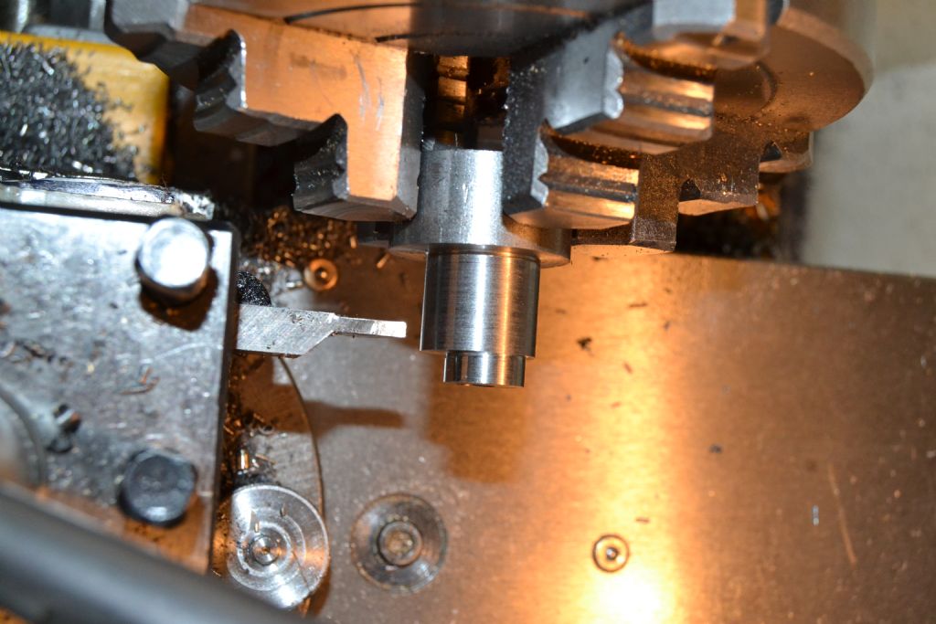
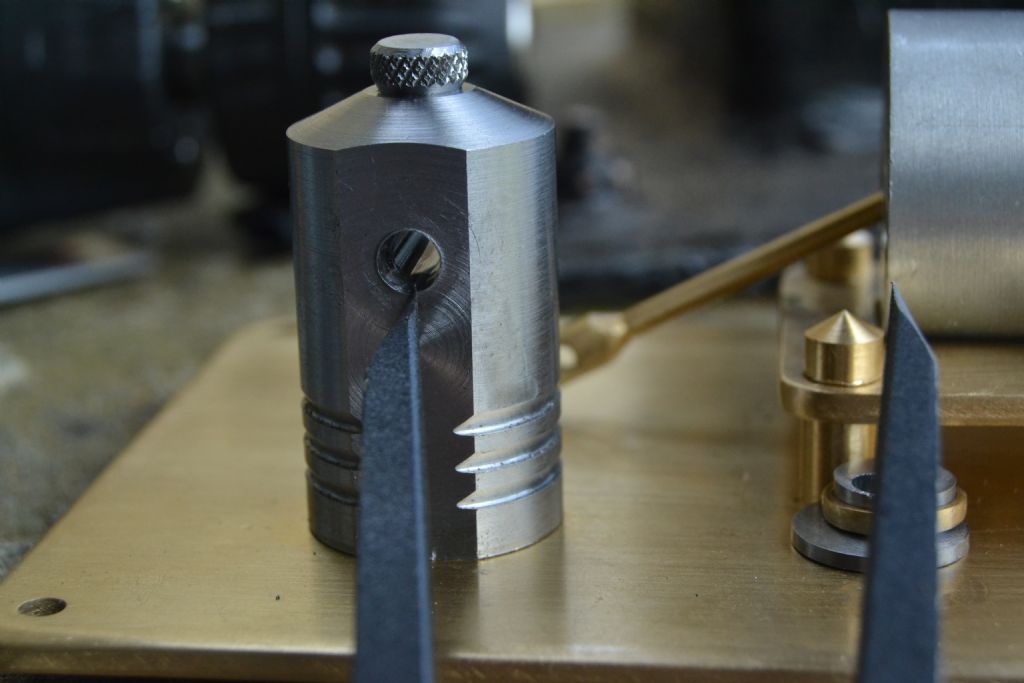
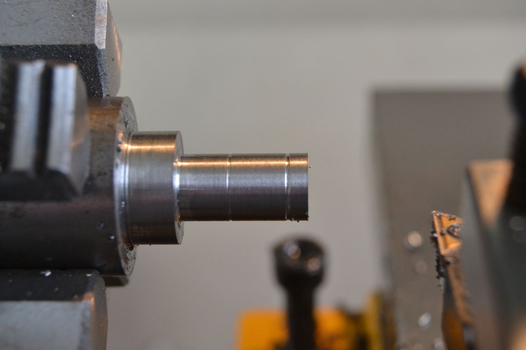
So using this crude method I cut small reference grooves in the work piece marking the parting cut position. I did the same method for the other spacer hoping I'll get 3 components in one procedure.


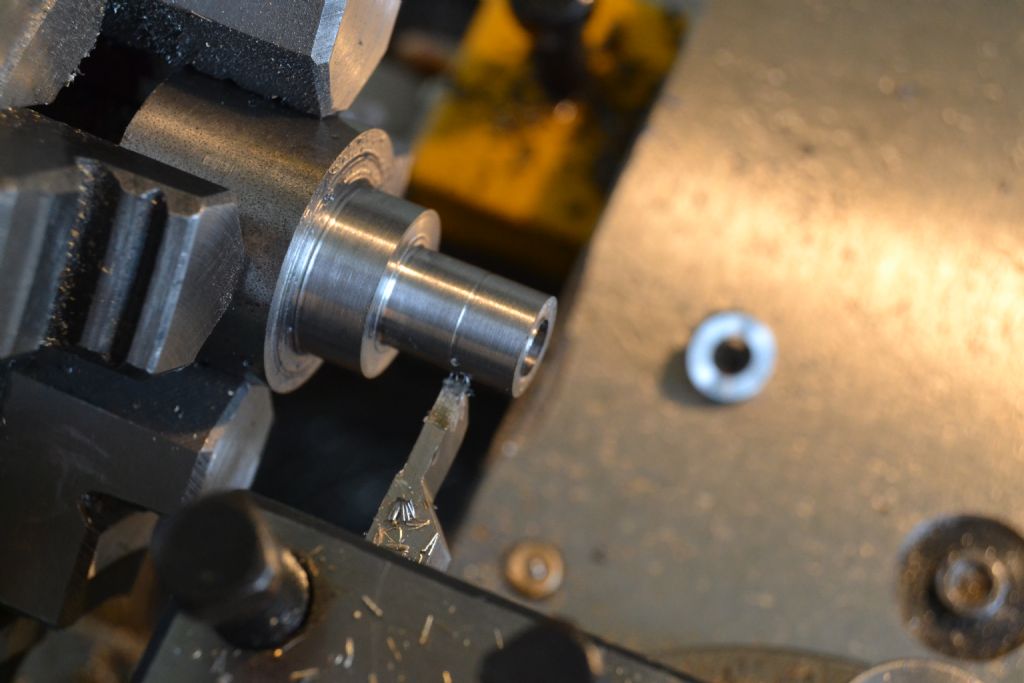
Parting tool at the ready and here we go, buy 1 get 2 free.


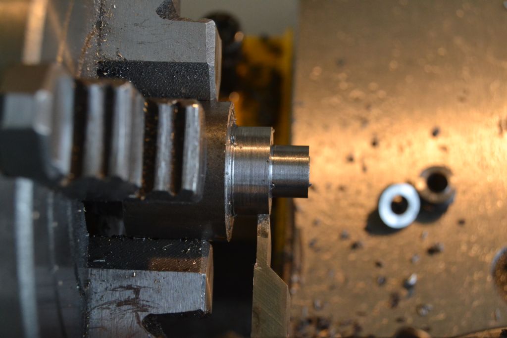
I took the next photo at the wrong time, it should show the tool further left to part off a disc for the eccentric, but you get the idea.

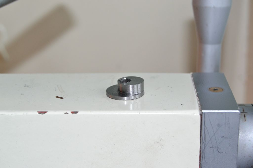
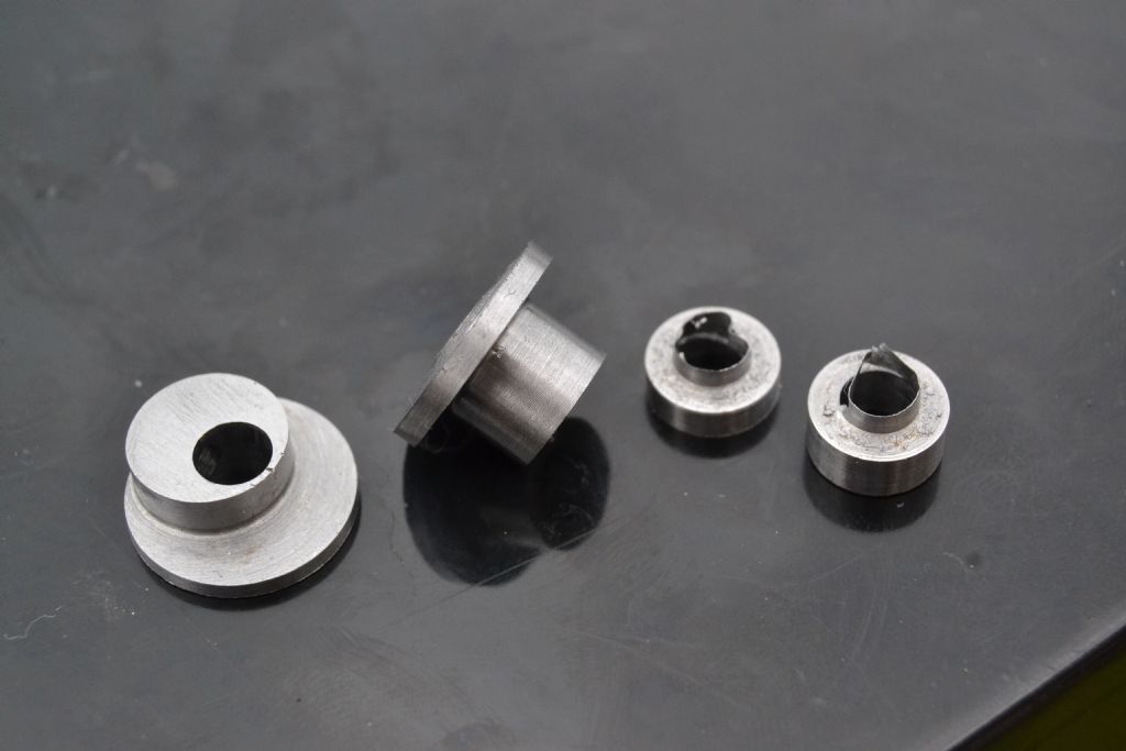
I end up with these 3 and just a bit of filing and tidying up to do.

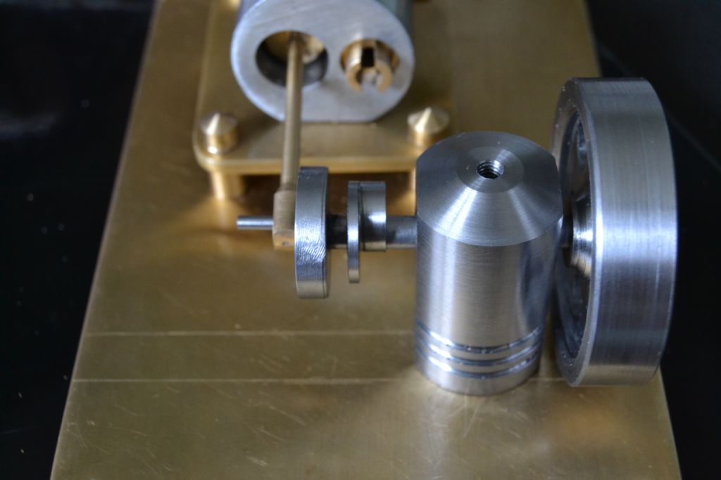
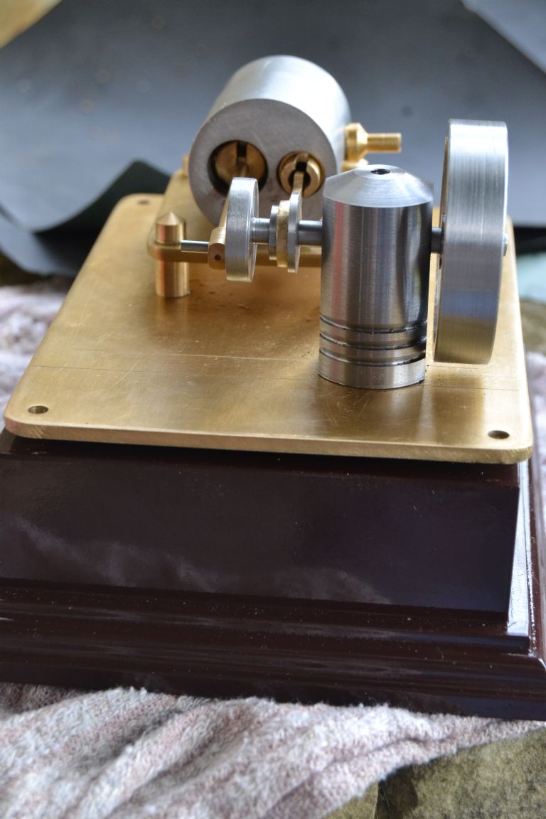
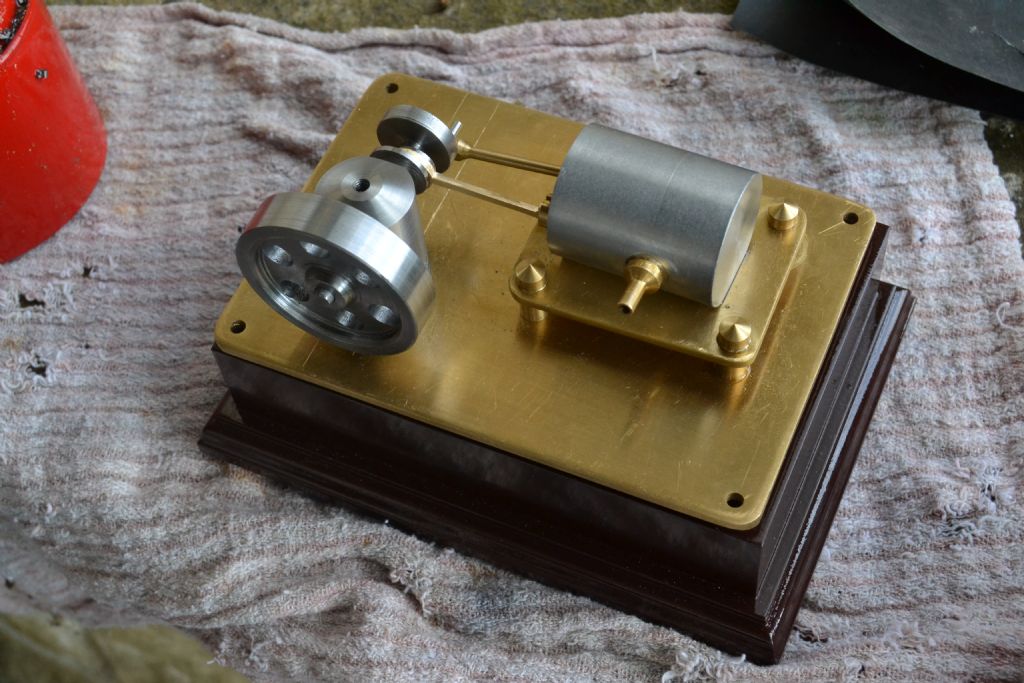
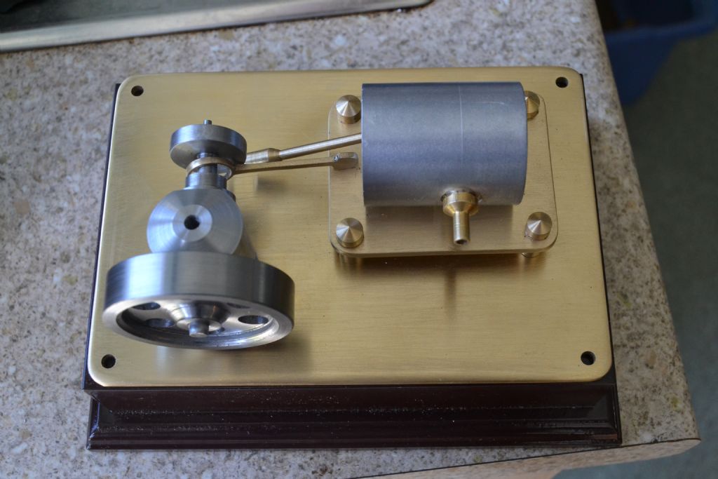
Looking like a 'proper' crank assembly.

Well does it work ?
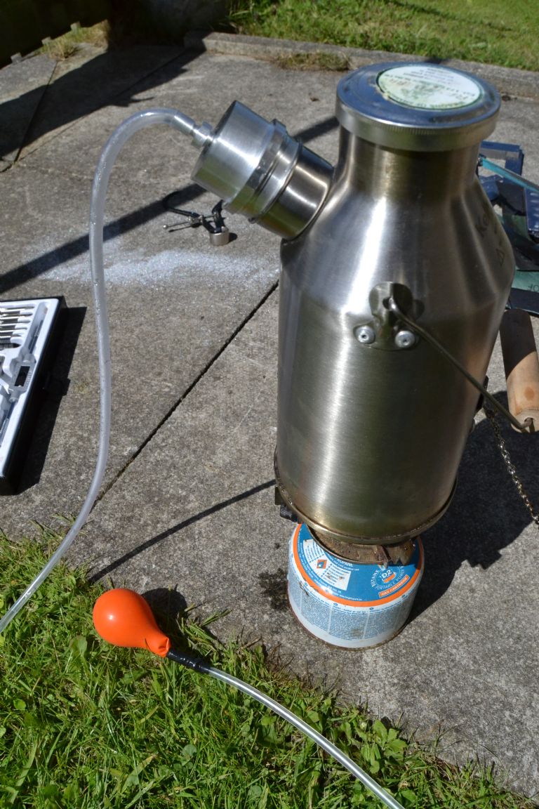
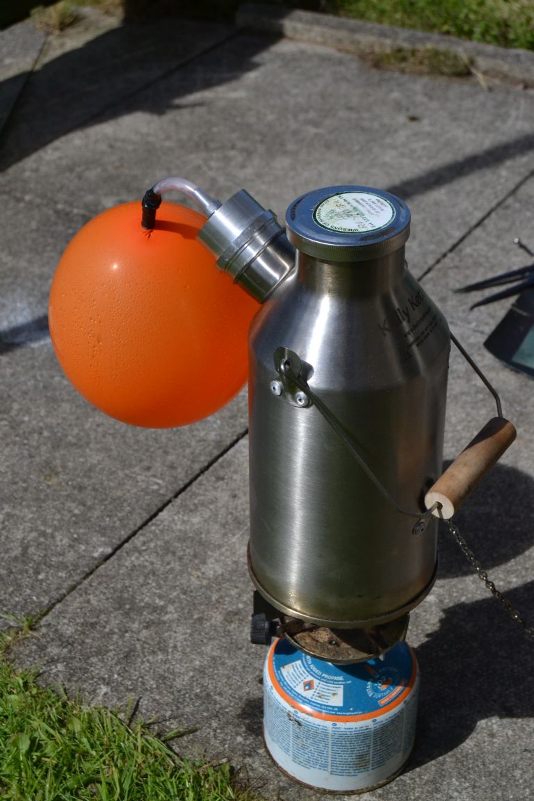
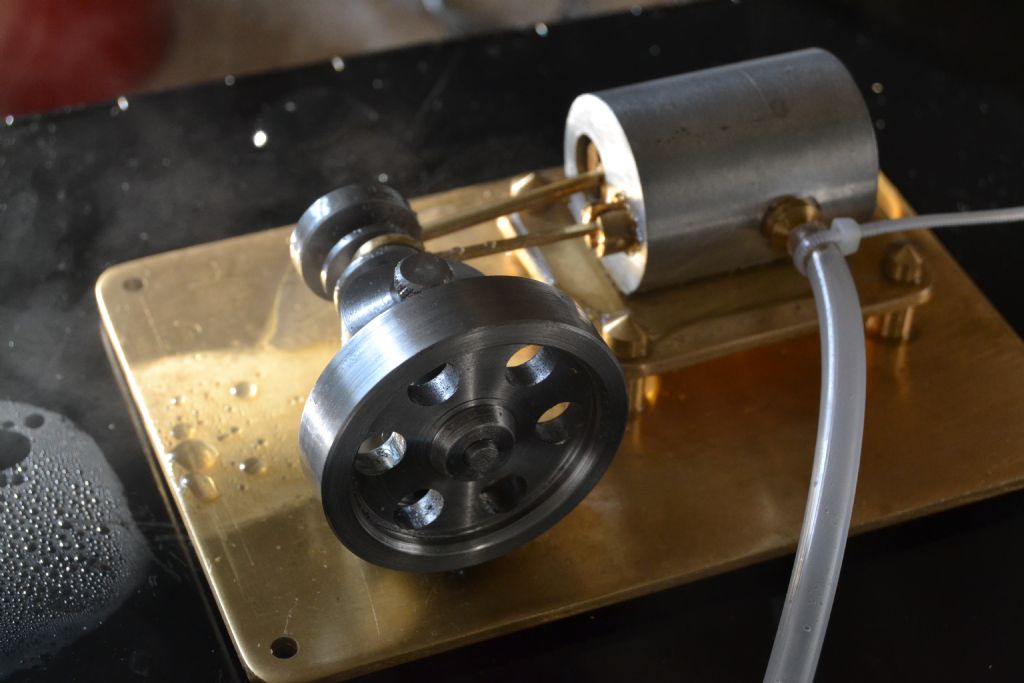
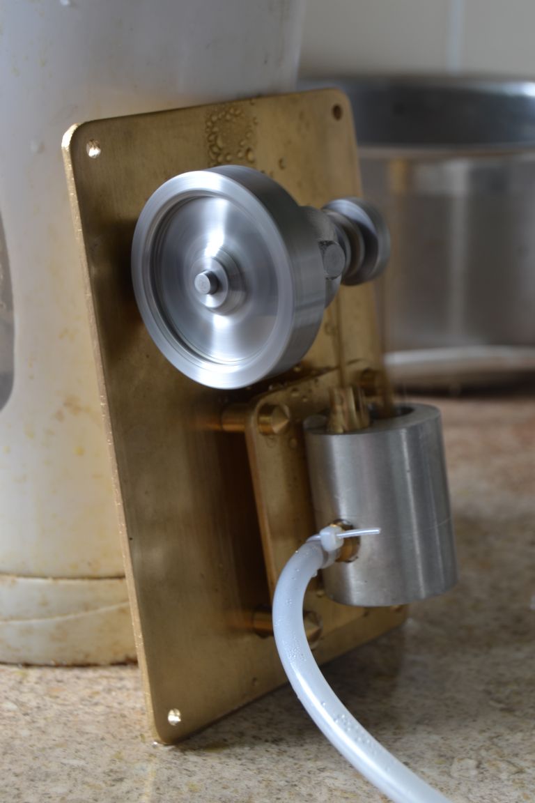
I rigged it up to a Kelly kettle and aquarium tubing and although it coughs splutters and hisses it does kind of work.

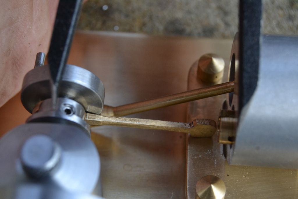
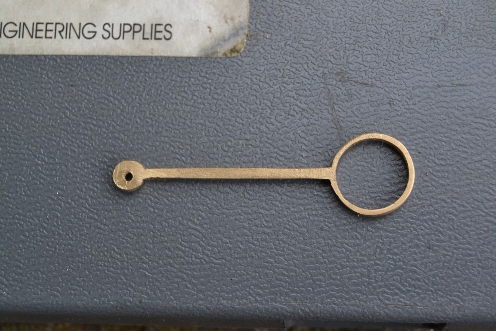
The eccentric rod has a bit too much lateral movement and the valve piston is a shade too small in diameter. the result is steam escapes past the valve as it wavers in the cylinder.
I'm going to file down the eccentric today and make a better fitting valve piston in the hope of rectifying what I think is the main issue.
I'm confident it will work though, the valve although a bit sloppy in side to side travel does seem to operate properly.
Peter.
<
Gas_mantle..


