Beginner making first steam engine

Advert

Beginner making first steam engine

Home Forums Work In Progress and completed items Beginner making first steam engine

Viewing 25 posts - 1 through 25 (of 66 total)
  • Author
    Posts
  • #194971
    Gas_mantle.
    Participant
      @gas_mantle

      Hi all,

      As a complete beginner to this hobby and someone who has only owned a lathe a few weeks I feel I'm now getting past the 'swarf making stage' and have decided to try and built my first steam engine.

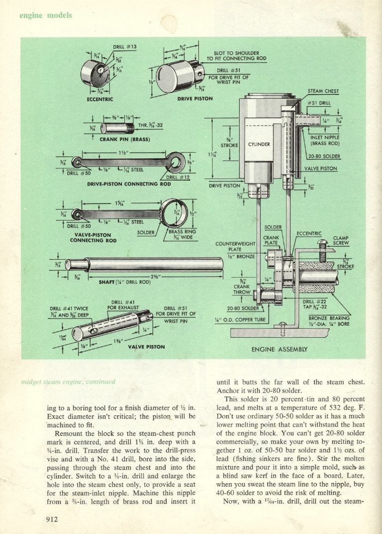
      I've decided to have a go at this :-

      **LINK**

      If it proves to be beyond my skill level I'll put it to one side for a few weeks till I have the necessary skills and/or tools to do the job.

      The plans are in imperial but I've decided to work in metric (my lathe and measuring equipment are all metric) so whilst I am working to the basic design the measurements are flexible and I'll modify / embellish it as I go along.

      As I say I am a complete beginner so if people want to offer me advice or tell me better ways of doing things I'm more than happy to listen.

      Here goes :-

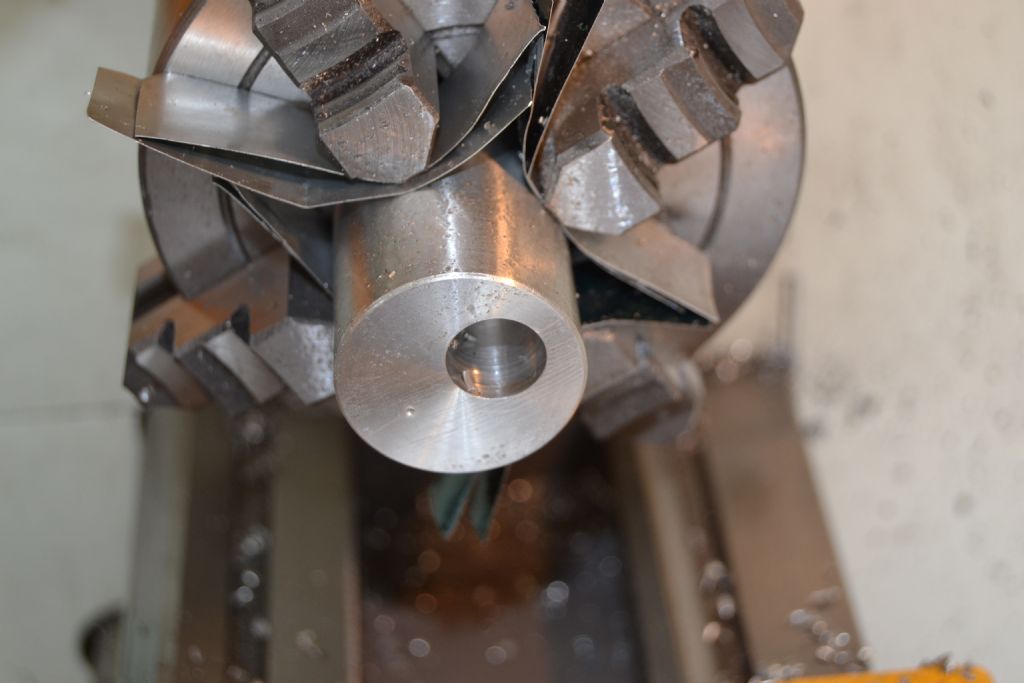
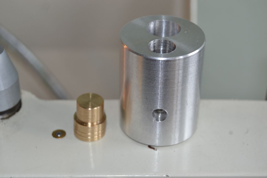
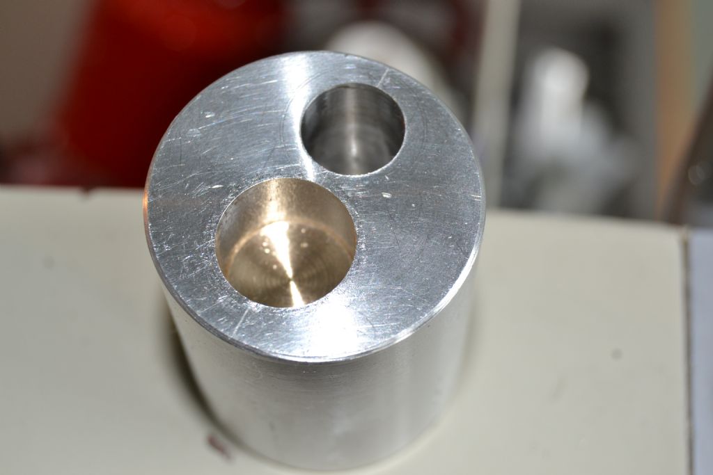
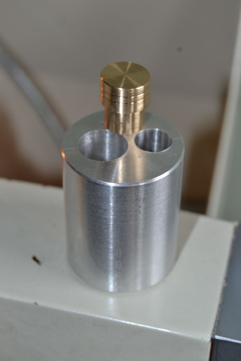
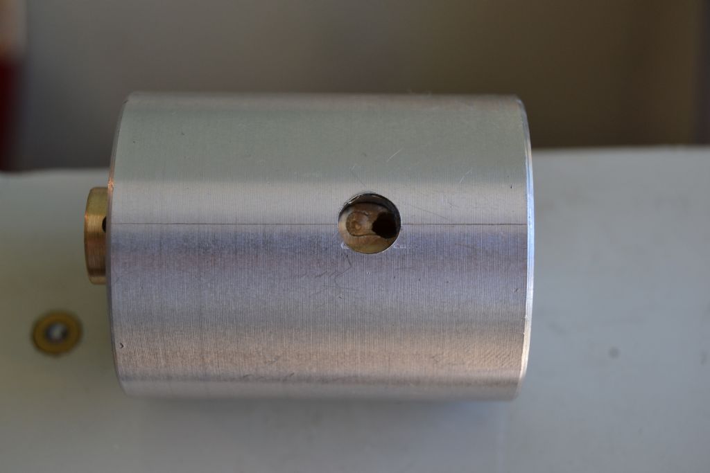
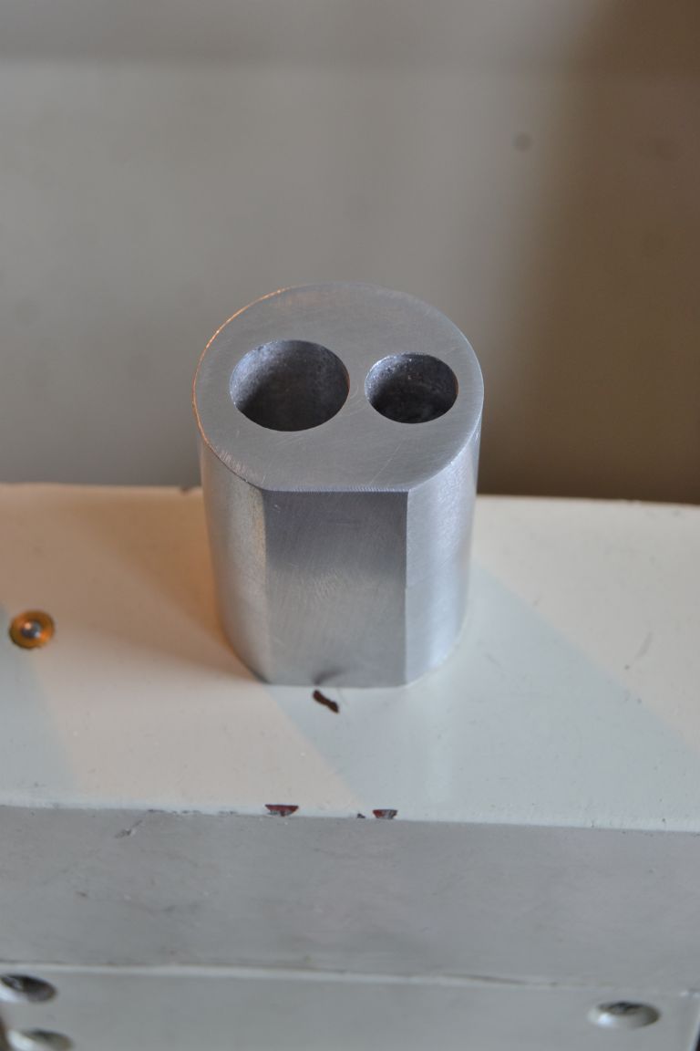
      Firstly I decided to machine the cylinder block / steam chest, I didn't have a piece of brass big enough to hand so I settled for aluminium (It's unlikely the engine will ever see live steam so I figured aluminium will do for compressed air).

      Block turned and faced to size then power piston bore done.

      dsc_0010.jpg


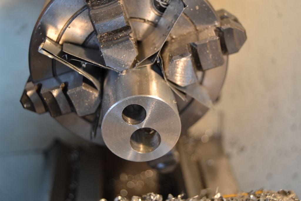
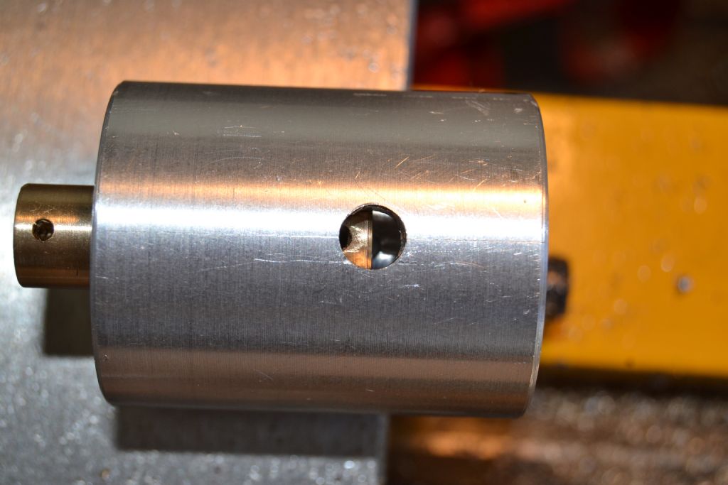
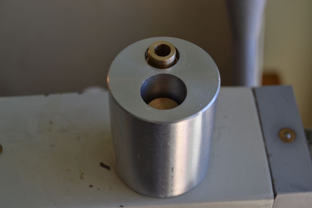
      Steam chest bore done, I decided to make this slightly larger diameter than the plans as I think that may prove more forgiving at my skill level.

      dsc_0015.jpg


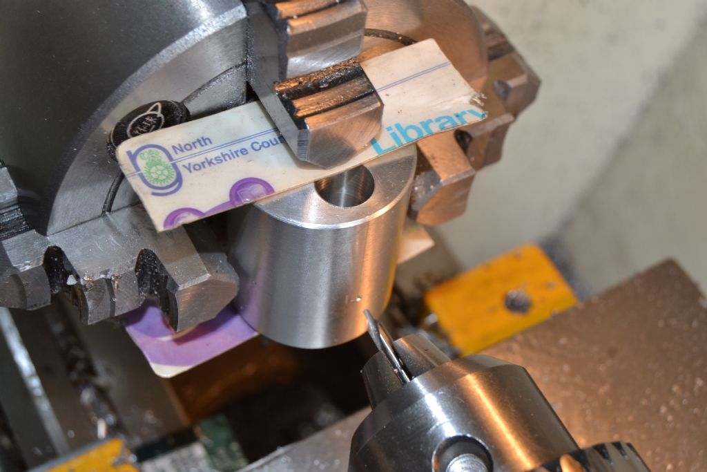
      Ready to begin drilling inlet port.

      dsc_0023.jpg


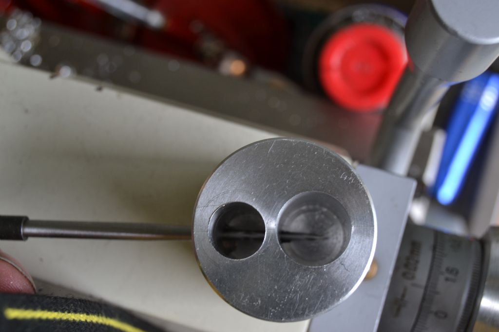
      Drilled through as far as power cylinder, I was a bit relieved at this point. With my limited tools and experience I wasn't certain how parallel the bores were etc. However once the inlet was drilled through my scriber seems to suggest they are reasonably true.

      dsc_0025.jpg


      I decided to omit mounting holes for the cylinder at this point as I'm not yet certain how I'll go about it but will probably deviate from the plan.

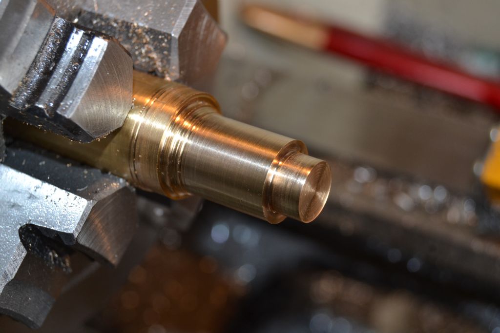
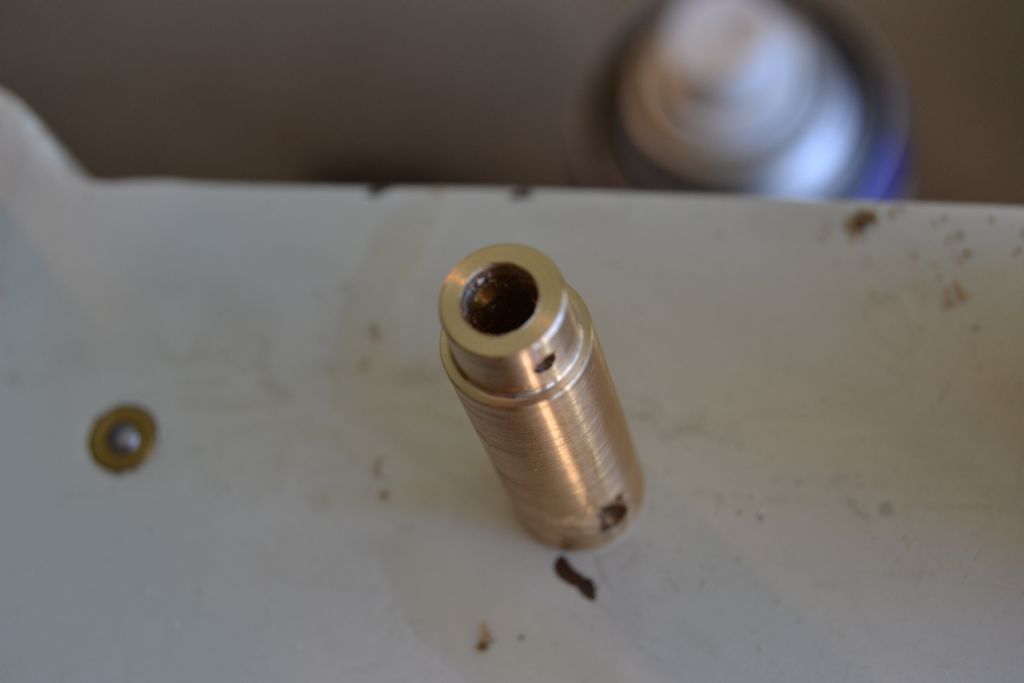
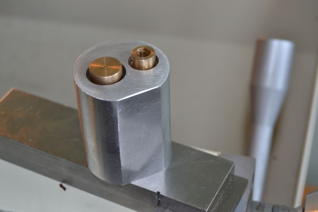
      So – I decided on the piston next. This time I had a suitable piece of brass

      dsc_0038.jpg


      I did damage the first piston when I turned it around in the chuck but had better luck second time

      I decided to cut in a couple of very small oil rings that aren't on the plan but I thought they may help me get a better airtight seal.

      dsc_0001.jpg


      dsc_0002.jpg

      dsc_0003.jpg

      Edited By Peter Nichols on 26/06/2015 12:22:38

      Advert
      #31087
      Gas_mantle.
      Participant
        @gas_mantle
        #194995
        Ady1
        Participant
          @ady1

          I found a couple of pages about rescaling recently which you may find useful

          #194998
          GarryC
          Participant
            @garryc

            Hi Peter

            Nice to see you starting your first engine, I'll be following all the way..!

            Enjoy, and the very best of luck with it.

            Regards

            Garry.

            #195044
            Gas_mantle.
            Participant
              @gas_mantle

              Thanks guys.

              Ady that thing about rescaling brings back memories, I was taught that at school 40 yrs ago and completely forgot about till you mentioned it. The article also mentions slide rules ! I even remember them from school too

              I been having another look at the plans and have decided to try and make the con rods a bit more attractive than the plans and possibly machine the cylinder top off then make a separate bolt on cylinder head, that would make it a bit more attractive and allow me to see what's happening in the cylinders when it comes to adjusting the valve timing.

              Peter.

              #195058
              V8Eng
              Participant
                @v8eng

                You might find brass and aluminium is a poor combination corrosion wise.

                Looks nice, keep up the good work.

                Edited By V8Eng on 26/06/2015 22:17:34

                #195099
                Ian S C
                Participant
                  @iansc

                  I put aluminium fins in the copper cooling tank of one of my hot air engines. The motor was driving a little generator, and I was checking the voltage, for some reason I put the metre across the fins, and copper tank, result .5 of a volt.

                  Aluminium is a poor choice for a sliding contact in it's ordinary state, it improves with anodizing, or as in some small IC engines chrome plating. It will work, but wear quickly, but a good practice session for your new lathe.

                  Ian S C

                  #195110
                  steamdave
                  Participant
                    @steamdave

                    For a low power compressed air operated engine, I think you will be fine with the metal combination you have chosen. It is not as if you will be running it for hour upon hour, so it will take Years before you get any significant wear.

                    Across the Pond, particularly, ali/brass combination is used more frequently than any other in small air models. Have a look at the HMEM site. http://www.homemodelenginemachinist.com/

                    Dave
                    The Emerald Isle

                    #195125
                    Gas_mantle.
                    Participant
                      @gas_mantle

                      Hi all,

                      Thanks for the advice, I didn't have a piece of brass the right size so I just used aluminium without thinking too much about it. I've now made the valve/exhaust piston also, with both pistons done they seem to fit nicely and slide smoothly, whether it will run is another matter !

                      Thinking ahead a little, I'm intending to try it on compressed air, can anyone advise me what is the usual diameter airline for such models so I can machine an appropriate sized inlet fitting ?

                      The plans go on about soldering a tube etc, I'd rather just insert a threaded fitting to accept a small airline.

                      Thanks

                      Peter.

                      #195129
                      steamdave
                      Participant
                        @steamdave

                        Ordinary aquarium plastic airline will do just fine. A barbed type fitting or one with a knob on the end will hold the airline in place. You don't want sharp ridges because the tubing might tear.

                        Have you considered what air system you will use? If it will be a one off air powered engine, consider getting an airbrush compressor. They put out a sufficient volume and pressure to run one or two little engines at a time. They are also very quiet compared to the usual Aldi/Lidl 2 HP or bigger versions they sell from time to time.

                        Dave
                        The Emerald Isle

                        #195130
                        Gas_mantle.
                        Participant
                          @gas_mantle

                          Hi Steve,

                          I did think about air supply and initially considered an aquarium pump but having since looked around I've seen paint spraying kits with a compressor for just over £60.

                          Something like this was what I'd thought about :-

                          **LINK**

                          I think I'd rather pay the extra and get a spraying kit, it's bound to come in handy for hobby work.

                          Peter.

                          #195141
                          steamdave
                          Participant
                            @steamdave
                            Posted by Peter Nichols on 27/06/2015 14:11:53:

                            Hi Steve,

                            I did think about air supply and initially considered an aquarium pump but having since looked around I've seen paint spraying kits with a compressor for just over £60.

                            Something like this was what I'd thought about :-

                            **LINK**

                            I think I'd rather pay the extra and get a spraying kit, it's bound to come in handy for hobby work.

                            Peter.

                            That's the type of copressor I was meaning.

                            Dave
                            The Emerald Isle

                            #195143
                            JasonB
                            Moderator
                              @jasonb

                              If you are getting an airbrush compressor and all teh bit sthen make a threaded union to take the airbrush hose.

                              As Dave says you should be fine with ali/brass, I have quite a few ali pistons running in bronze cylinders so similar situation and no problems with them.

                              #195159
                              Gas_mantle.
                              Participant
                                @gas_mantle

                                Hi all,

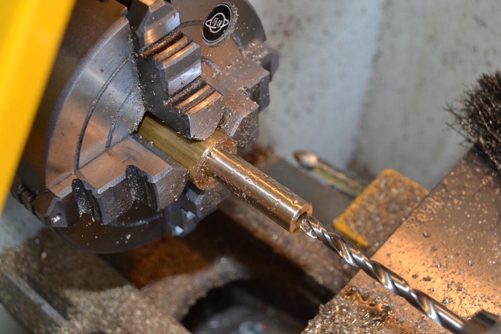
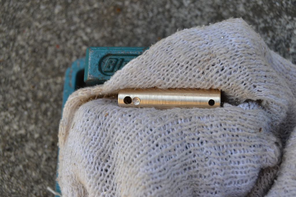
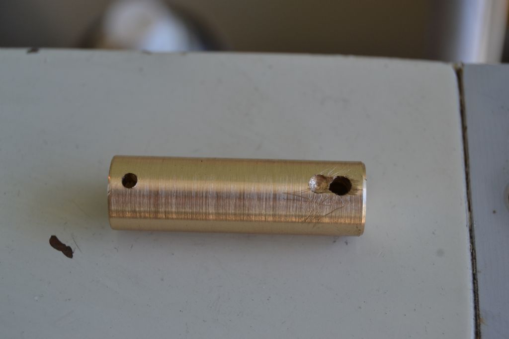
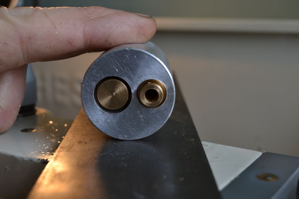
                                Today I thought I'd have a go at making the valve/exhaust piston, It's basically just a brass cylinder bored through to a blind end just a few mm before passing right through with an slotted exhaust port bored in at 90* to meet the central bore.

                                spoolvalveengine2.jpg

                                Firstly I faced, turned, and bored out to fit the cylinder bore.

                                dsc_0015.jpg

                                To drill the exhaust port I decided that without a bench drill I'd probably be just as well using a rechargeable power drill. I realise that isn't a precise method but I'm only wanting to drill 2mm holes only 2-3 mm deep and minute accuracy isn't crucial. As can be seen the hole and adjoining recess aren't perfectly aligned but I think they will meet the requirements

                                dsc_0018.jpg

                                I struggled to file the slot alongside the exhaust inlet and although it's not attractive it does appear to be the right size and in the right place.dsc_0020.jpg

                                This photo shows the piston valve at it's furthest travel so TDC will be just slightly short of this position, so for now at least I'm satisfied the valve will align with the port correctly when turned 180* to face the power cylinder port.

                                dsc_0022.jpg

                                The next photo shows the top of the valve piston with the inlet port for the power cylinder just about visible at the back. So I'm hoping that once the valve piston has been rotated to face the power cylinder port the exhaust will line up near TDC. Well that's the theory anyway !dsc_0026.jpg

                                The valve piston now with a shoulder turned at the con rod end (that I should have done earlier but forgot !) All the remains is to cut a slot to accept the con rod.

                                dsc_0034.jpg

                                Both pistons and the cylinders almost complete.

                                dsc_0037.jpg

                                Peter.

                                #195244
                                Gas_mantle.
                                Participant
                                  @gas_mantle

                                  Hi,

                                  Although the plans have this as a vertical engine I'd prefer to have it as a horizontal so have been doing a lot of thinking how I might best go about it. Part reason I didn't try a 'wobbler' as a first project was that without access to a milling machine I didn't feel I could reliably file the necessary flat face by hand with sufficient accuracy.

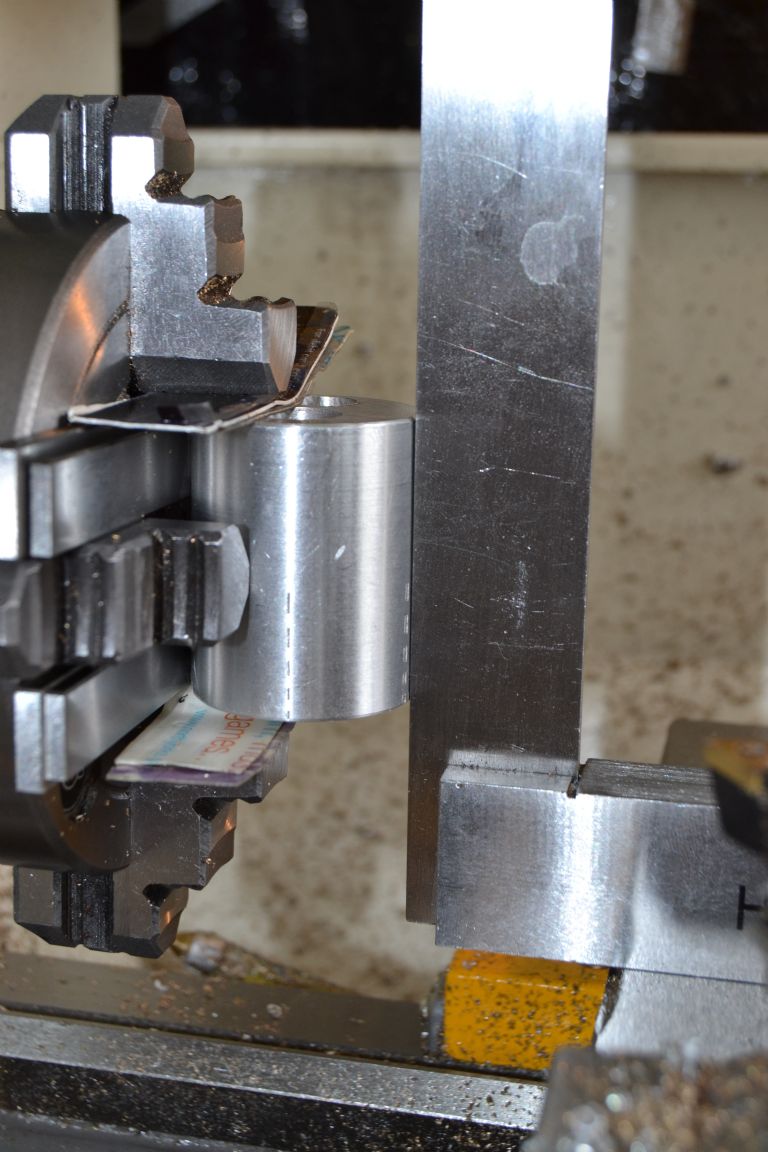
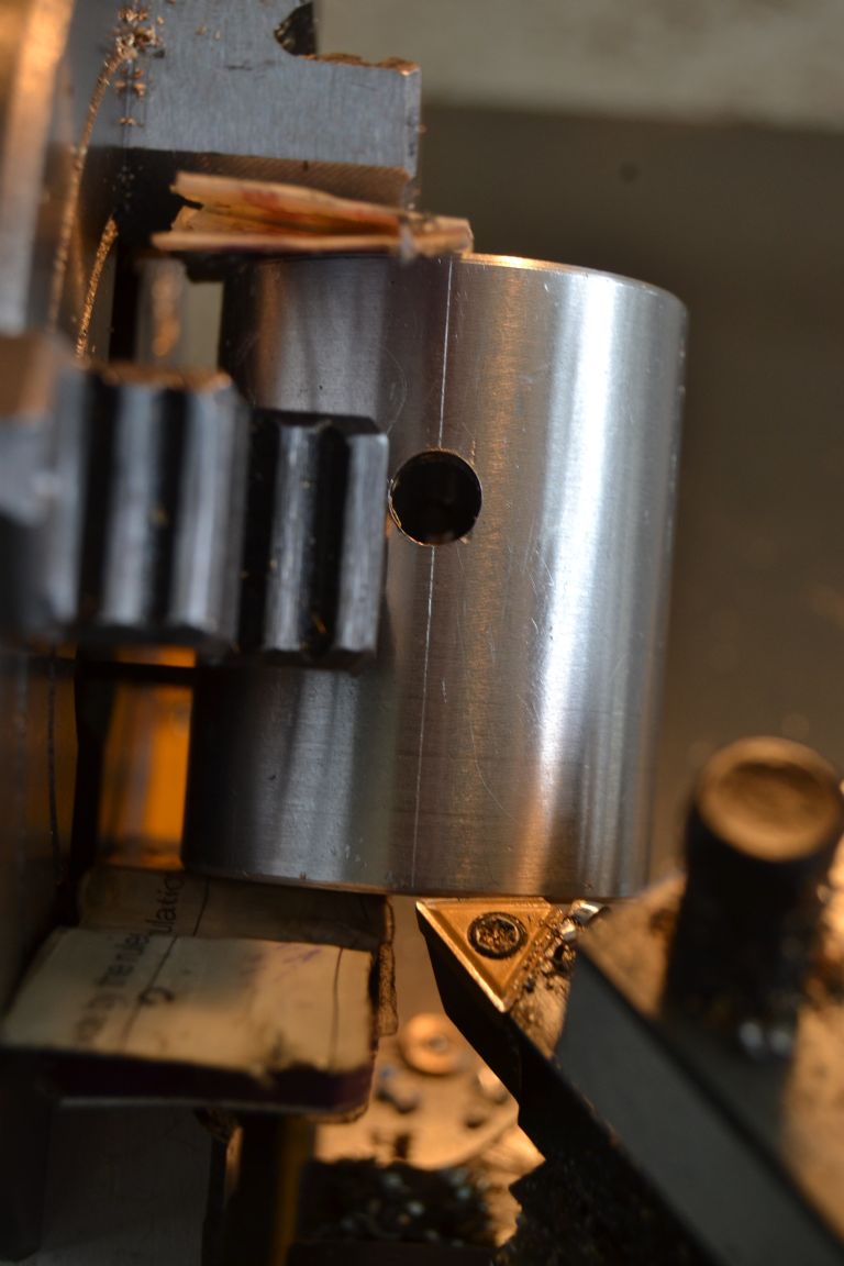
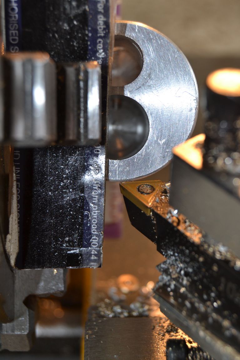
                                  After some helpful advice from other members here they suggested I could face off a piece placed a cross the lathe chuck if I was careful about it.

                                  I decided I wanted to bottom mount the cylinder block and reasoned the only way was to face off in the way others had suggested, with the intention of bolting it to a plate. The cylinder walls are fairly thin and bottom mounting seemed the best option.

                                  steamer4 (8).jpg


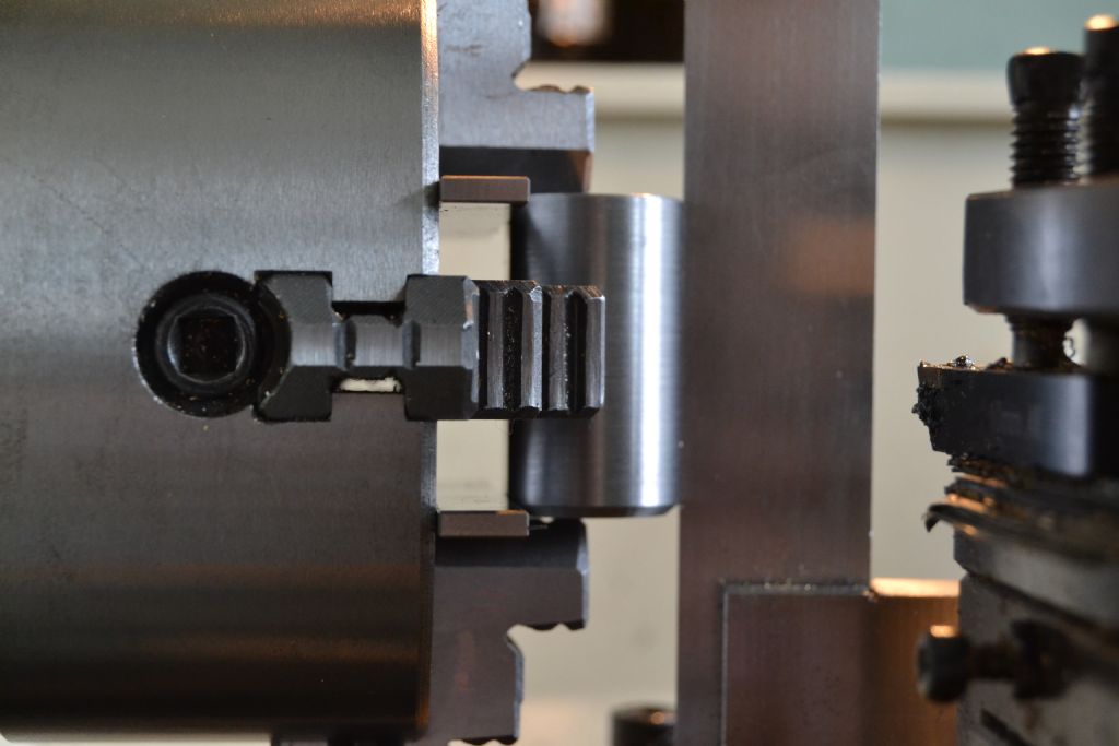
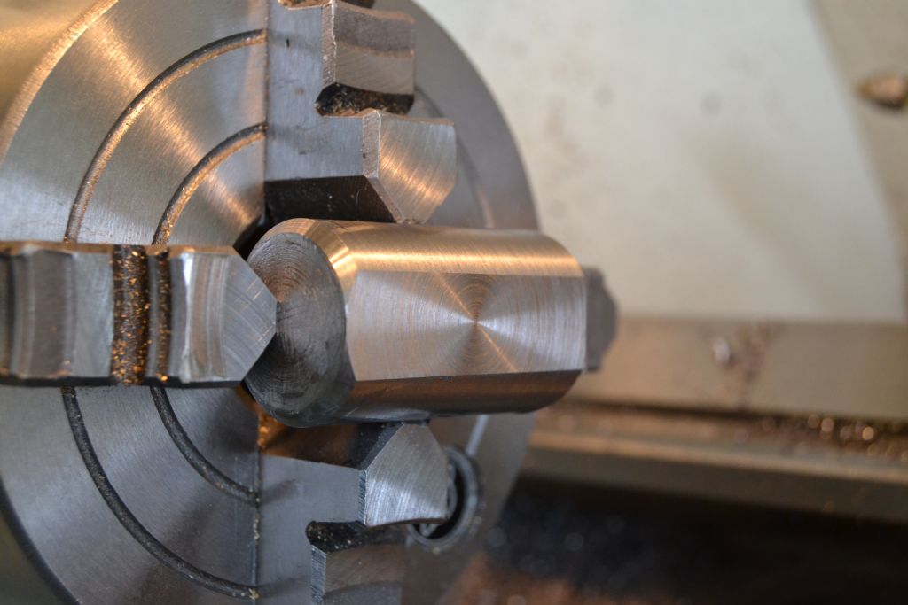
                                  I decided to have a test run with a piece of similar sized aluminium and sure enough it worked with ease. At least now I know that till I get a mill it is possible to do very basic 'milling' in the lathe. As this was only a test piece I didn't go to the trouble of lining it up properly but you get the idea.

                                  steamer4 (4).jpg


                                  I figured that lining up would be a problem but with the use of parallels and a few faint scribe markings that were still left from earlier drilling operations I could just about manage. I used the tool point to align with the scribe markings and rotate the work by hand in the chuck 180* whilst not moving the tool.

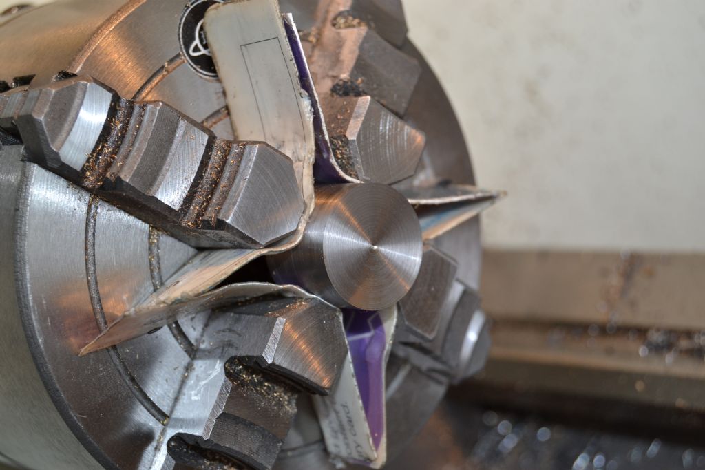
                                  In order to get access to the scribe markings along the centre line I needed the work out of the chuck slightly beyond its diameter so it's actually only being held firmly by the 2 flat ends with the other 2 chuck jaws gently touching the curved sides. I realise that's far from ideal but the intention is to take light cuts on a soft material and I have got a very firm grip of the flat ends of the work.

                                  steamer4 (11).jpg

                                  steamer4 (13).jpg

                                  steamer4 (15).jpg


                                  Success ! – A bit of filing and tidying up to remove a few minor scrapes and chuck marks and also seems to be ok.

                                  steamer4 (20).jpg

                                  steamer4 (29).jpg


                                  Edited By Peter Nichols on 28/06/2015 15:34:48

                                  #195326
                                  Ian S C
                                  Participant
                                    @iansc

                                    Found it, I thought I recognized the plan, not too sure about the boiler that is suggested, others may know, it's from Popular Mechanics, and the boiler is made from a 6" X 2" water pipe nipple, with a pipe cap on each end. I would not trust water pipe, the bit of 1 3/4" pipe I used to make a cylinder for my second hot air engine split along the seam when I bored the weld bump off(welded it along the outside and it's still going).

                                    At least you picked an easier one than I did from the same source, I built the Elbow Engine, it takes up room on my model shelf.

                                    Ian S C

                                    #195337
                                    Gas_mantle.
                                    Participant
                                      @gas_mantle

                                      Hi Ian,

                                      I found the plans online, this is the link :-

                                      **LINK**

                                      Is it the same as you were thinking off ? I'm broadly working to it but adjusting a few dimensions to suit and intend it to be a horizontal rather than the vertical in the plan.


                                      I'd have liked to start on the con rods and possibly the main axle/crank next but decided I'd be better getting the cylinder mounted on a brass plate and on a piece of scrap wood for now, then I can look at where the crank needs to go etc and finally make the con rods to suit. I indend to make the rods out of round brass bar rather than the flat strips in the plan.

                                      I'm looking at buying a small compressor/airbrushing kit (about £65) as an air supply as the airbrushing is bound to come in handy as well but I did notice aquarium airline on Amazon – £2 with free delivery ! so I ordered some.

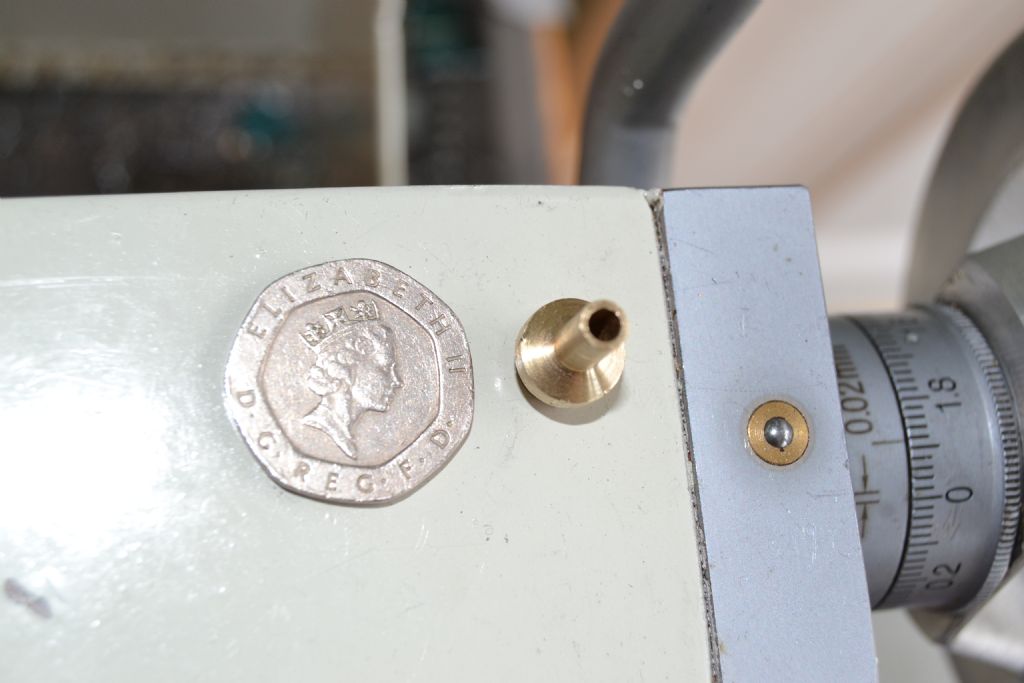
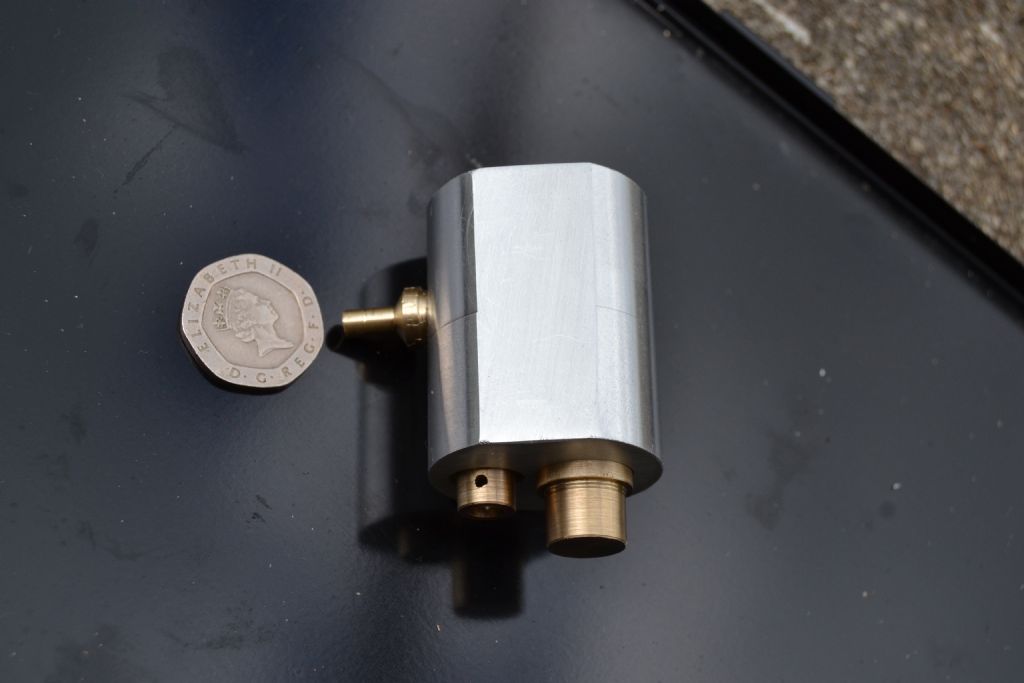
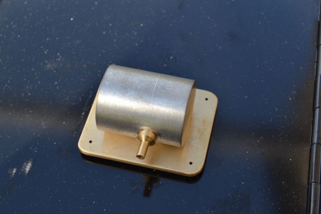
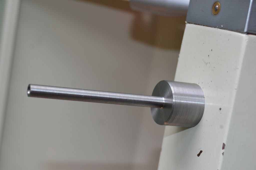
                                      Till I've decided how best to clean up the brass base plate I thought for today I'll just do the airline fitting, I didn't think ahead at the time but I decided to risk drilling it out to cut an M8 thread into the cylinder block as I think anything smaller wouldn't pass sufficient air.

                                      The result meant I have an M8 to 4mm airline fitting bored through to 2.5 mm, I wanted to try and bore it out a bit more but though I'd be pushing my luck

                                      dsc_0007.jpg

                                      dsc_0013.jpg

                                      I can't say I'm overly happy with the result but the likelihood is it will only be a temporary measure and it does look like it will do the job till I come up with a better idea.

                                      Peter.

                                      Edited By Peter Nichols on 29/06/2015 13:33:44

                                      #195415
                                      Ian S C
                                      Participant
                                        @iansc

                                        I'v got a set of Popular mechanics DIY books that Dad had, it's a collection of articles from the magazine. The suggested cylinder is bronze, and the piston cold rolled steel, same for the valve piston.

                                        Ian S C

                                        #195426
                                        Gas_mantle.
                                        Participant
                                          @gas_mantle

                                          I started making it using the materials I had, so I'm hoping it will work using the materials I'm using.

                                          It's only ever going to have a few test runs on compressed air till I can get it running then it will be a glorified desk ornament so I'm not overly bothered about wear or efficiency issues so long as I can satisfy myself it is a 'working' model.

                                          #195470
                                          Ian S C
                                          Participant
                                            @iansc

                                            Peter, it sounds as though you work in a similar way to me, most of my time on a new construction is hunting around the workshop for the materials, spent half of today looking for some suitable steel to make a flywheel. I use mainly scrap steel that needs machining all over, over the years I'v built a few ornaments.

                                            Ian S C

                                            #195476
                                            Gas_mantle.
                                            Participant
                                              @gas_mantle

                                              Hi Ian,

                                              As I'm only starting out at this game I'm gradually building up a stock of materials (and tools) but for the moment working with what I've got till I have a better stock.

                                              #195554
                                              Ian S C
                                              Participant
                                                @iansc

                                                I think that's a good way to get going, you'll be surprised where some stuff comes from, look carefully at everything before you chuck it out.

                                                Ian S C

                                                #195706
                                                Gas_mantle.
                                                Participant
                                                  @gas_mantle

                                                  Hi all,

                                                  Since I've now decided the engine will be a horizontal rather than a vertical as in the plans I was faced with how to raise the cylinder block a little so that the line of the pistons travel will be in line with the main axle / crank assembly.

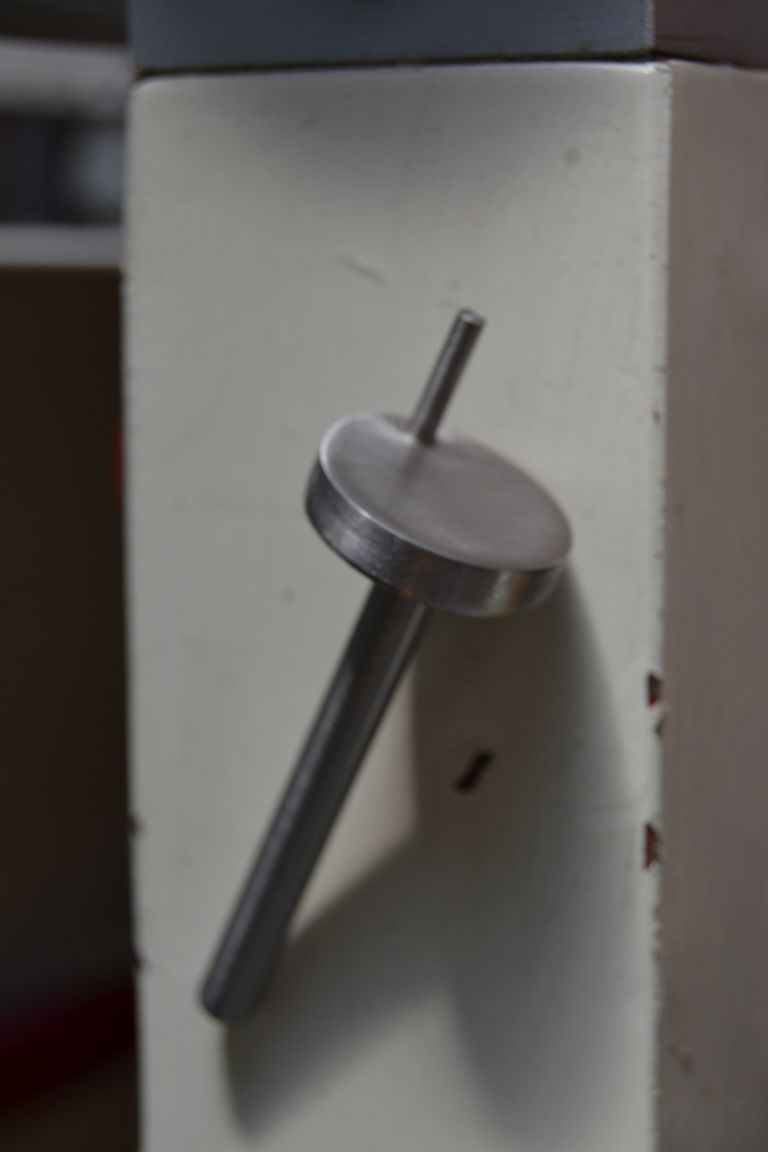
                                                  I took the rather unorthodox step of raising it on a small brass plinth. (I have limited materials and tools to work with) It may be unusual but I'm satisfied it will work and at least look presentable.

                                                  steamer7 (2).jpg

                                                  steamer7 (10).jpg

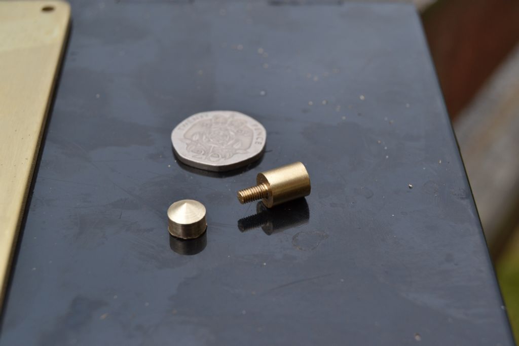
                                                  I decided to make the legs appear to be one piece although they are a glorified nut and bolt.

                                                  steamer7 (13).jpg

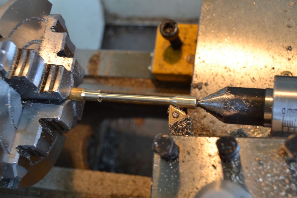
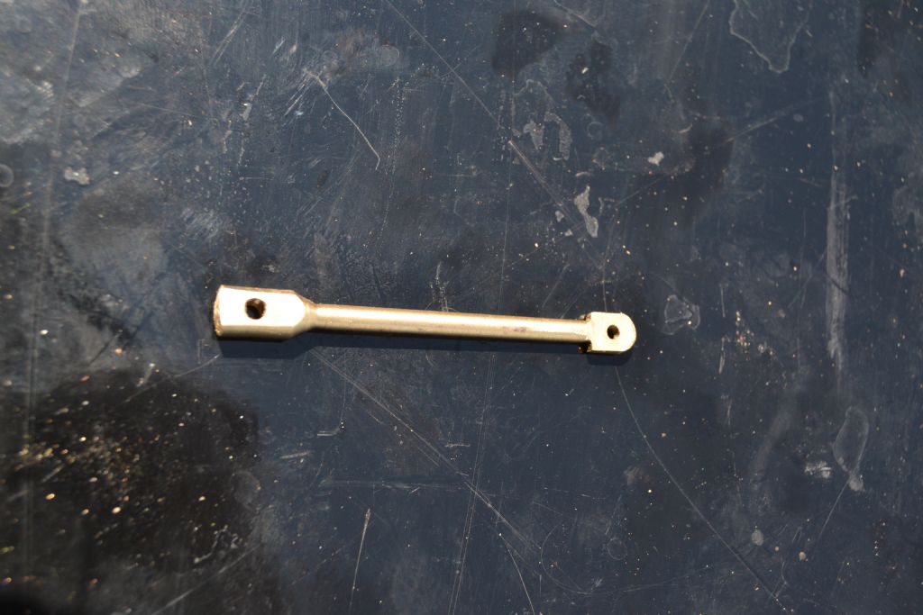
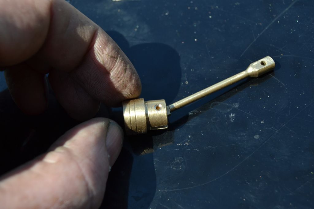
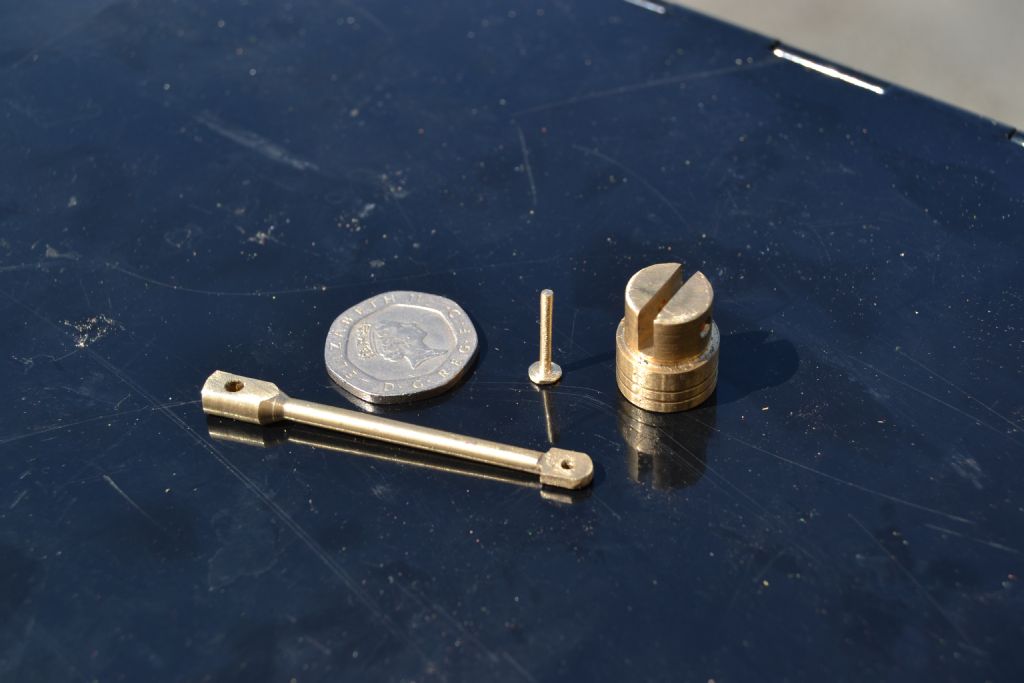
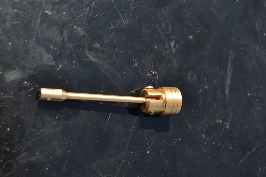
                                                  Next I opted to make the power piston con rod, I decided I wanted to make it out of a brass rod turned to size with the ends filed and drilled by hand.

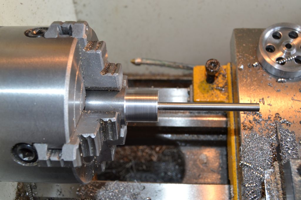
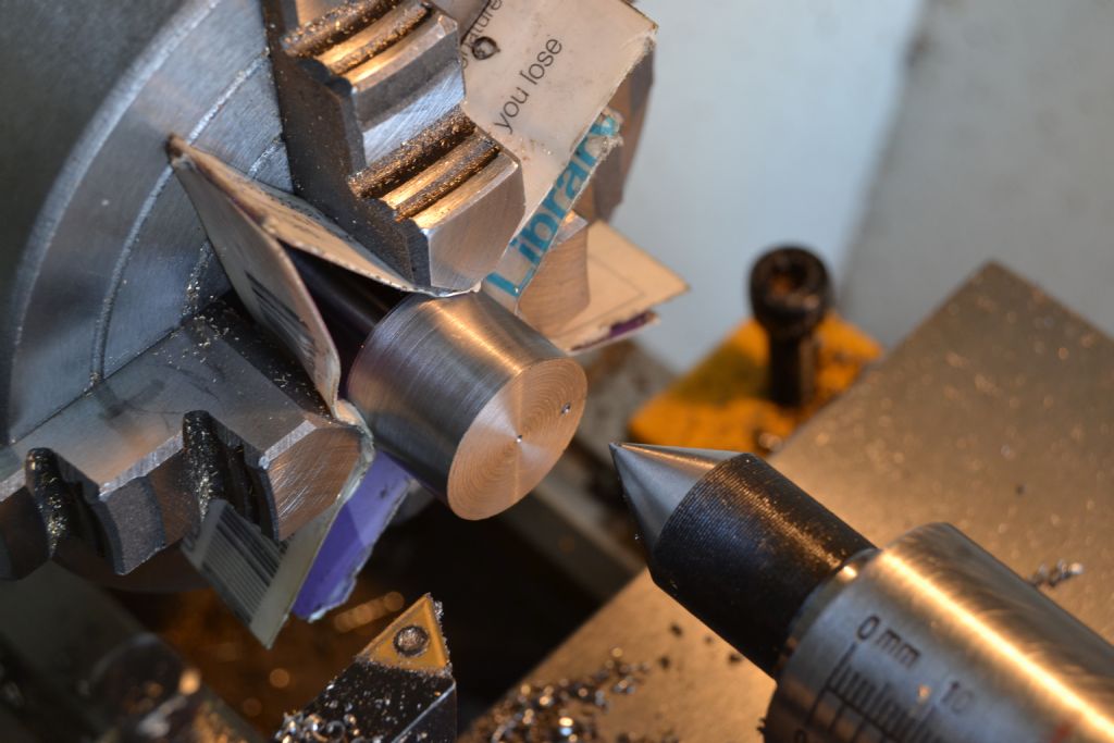
                                                  Since the diameter isn't critical I decided to turn between the chuck and a centre and hope I could get it thin enough to look right. I was pleasantly surprised that using this method and a bit of care I was able to get to about 3mm over about 60mm

                                                  steamer7 (20).jpg

                                                  steamer7 (22).jpg

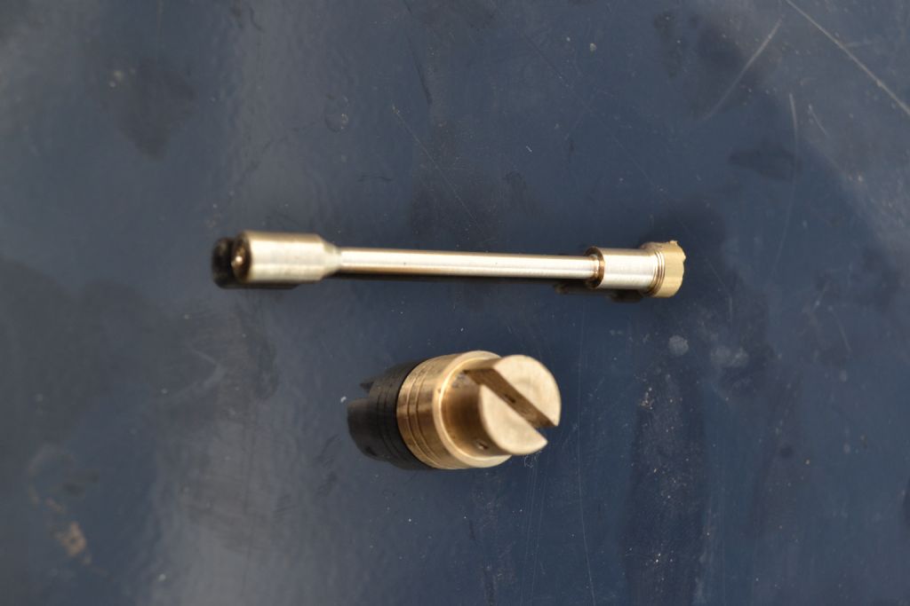
                                                  Half an hour of filing and drilling to arrive at this

                                                  steamer7 (28).jpg

                                                  steamer7 (31).jpg

                                                  So far I'm reasonably pleased with the result and ready to make the piston pin. The holes in the piston and con rod are 1.7mm so I'm hoping I can turn a short rod down to 1.5mm ish.

                                                  The pic below is at 1.7mm and just slightly too large, the only way I could figure out to get a few more cuts was to support it by holding a pen behind the work opposite the cutting tool. Not a very precise method admittedly, but it did work on a small workpiece where a good finish isn't important.

                                                  steamer7 (36).jpg

                                                  A few more careful passes and hey presto 1.5mm, just enough to allow the piston free movement.

                                                  steamer7 (37).jpg

                                                  I chose to keep a 'head' on one end of the rod and lightly pein the other end.

                                                  steamer7 (39).jpg

                                                  steamer7 (46).jpg

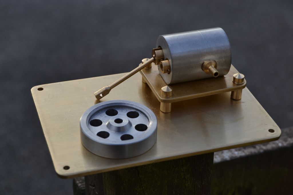
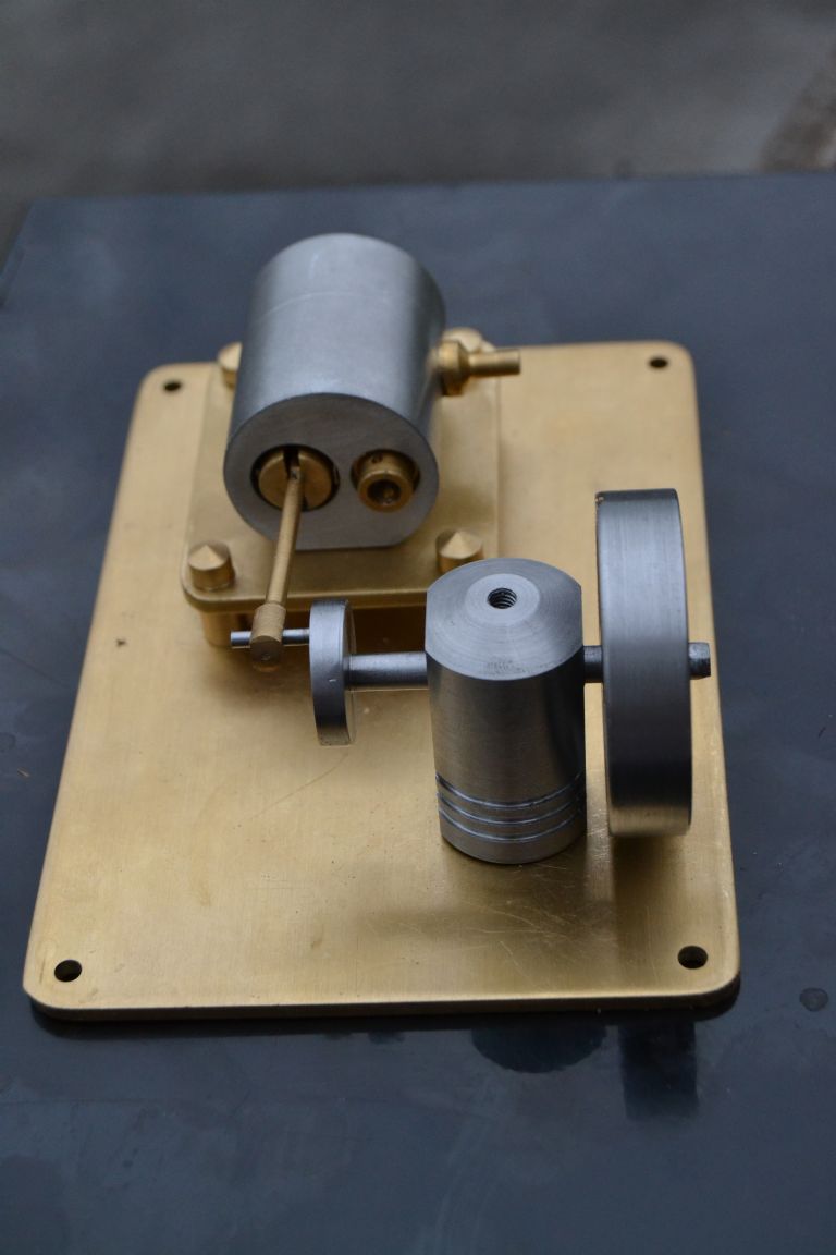
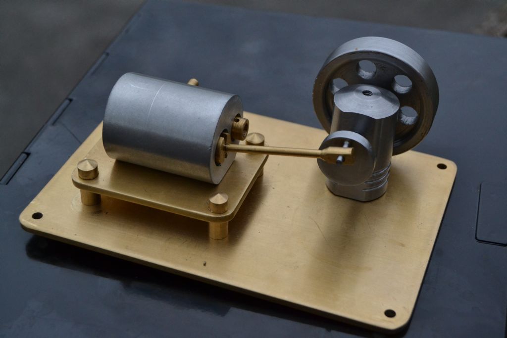
                                                  Which then nicely leaves me to its current state, with a flywheel I made a couple of weeks ago. The wheel wasn't made for this engine and needs tidying up to remove some grooves but with a bit of work may be suitable.

                                                  Starting to look a bit like an engine !

                                                  steamer7 (51).jpg

                                                  Peter.

                                                  #195782
                                                  Gas_mantle.
                                                  Participant
                                                    @gas_mantle

                                                    Hi,

                                                    I thought I'd have a go at the main axle and crank today but after the disaster I had trying to make my first crank disc a couple of weeks ago I wasn't confident.

                                                    I still can't see how it's possible to turn a small disc shaped work piece that doesn't have a central hole, at least with a hole I could make a temporary arbour.

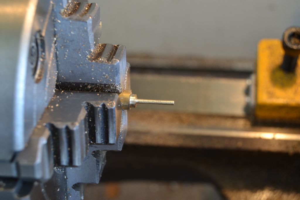
                                                    The only possible way I could see round the problem was to turn the entire axle, crank disc and crank pin out of a single piece (admittedly I could have done the crank pin as a separate item but chose not to)

                                                    Firstly I turned the axle and the end that would ultimately be the crank disc and crank pin to size.

                                                    steamer 8 (5).jpg

                                                    Then turned the work around to face off and make a small mark indicating the centre in order to assist marking out for the crank pin offset.

                                                    steamer 8 (6).jpg

                                                    So far so good, but I'm still not confident about trying to machine down the crank disc width and leave the offset pin.

                                                    steamer 8 (7).jpg

                                                    The main axle is 5mm diameter which doesn't seen enough to bear the strains of holding the work while I do the offset.

                                                    In order to hold the work by the widest part in the chuck I won't have much to hold on to if I want to make the crank disc relatively thin but this seemed the better option.steamer 8 (9).jpg

                                                    Surprisingly it worked better than I expected and after a bit of light filing and emery cloth use to get rid of a few chuck jaw marks I ended up with this.

                                                    steamer 8 (10).jpg

                                                    Although the method I used did work I'm sure there must be an easier way, can anyone suggest a better way of turning small disc shaped object without a central hole, particularly ones that need offset turning like the crank disc ?

                                                    Thanks

                                                    Peter.

                                                    Edited By Peter Nichols on 04/07/2015 21:23:42

                                                    #195978
                                                    Gas_mantle.
                                                    Participant
                                                      @gas_mantle

                                                      Hi,

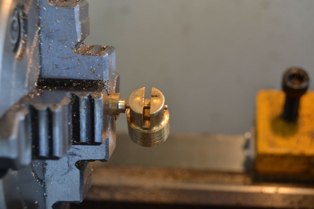
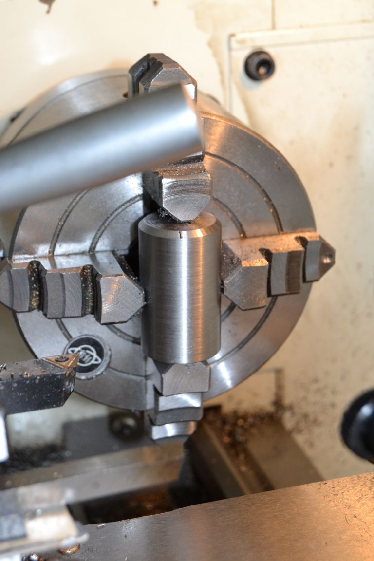
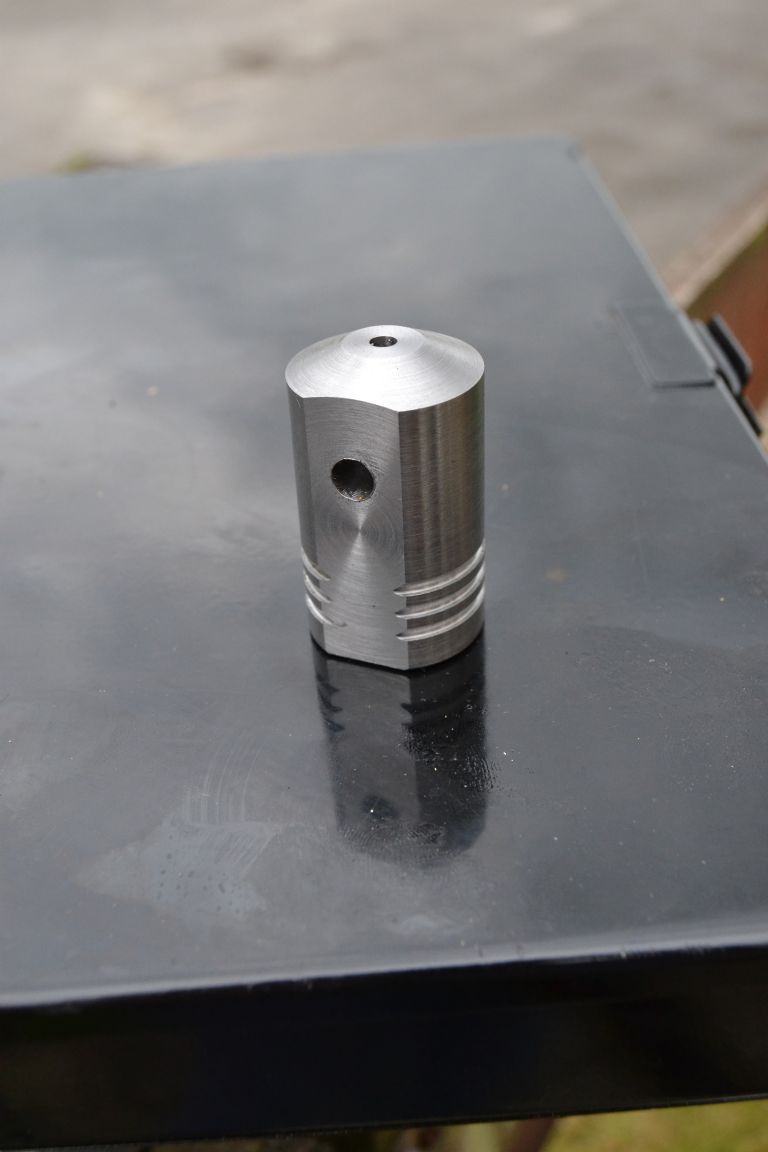
                                                      I had been wondering for a while on how best to support the main axle, given the small size of this engine I didn't feel there was enough room to have 2 separate supports and decided I use one relatively large diameter cylinder of mild steel and attempt to machine 2 opposing flat faces where the axle would enter and exit.

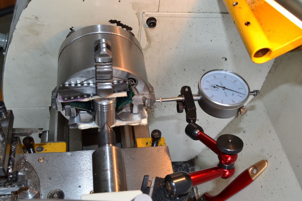
                                                      Yesterday when I began the task of making the mounting it turned out to be one disaster after another, I struggled to get anything square and at one point even resorted to using a dial indicator on the chuck jaws when I was running out of ideas.

                                                      steamer 9 (10).jpg

                                                      Eventually I did manage to drill the axle hole but it tuned out to be far from parallel to the base. Even in this small photo it's possible to see how far out of line it is.

                                                      steamer 9 (12).jpg

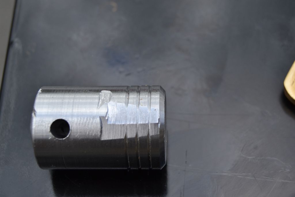
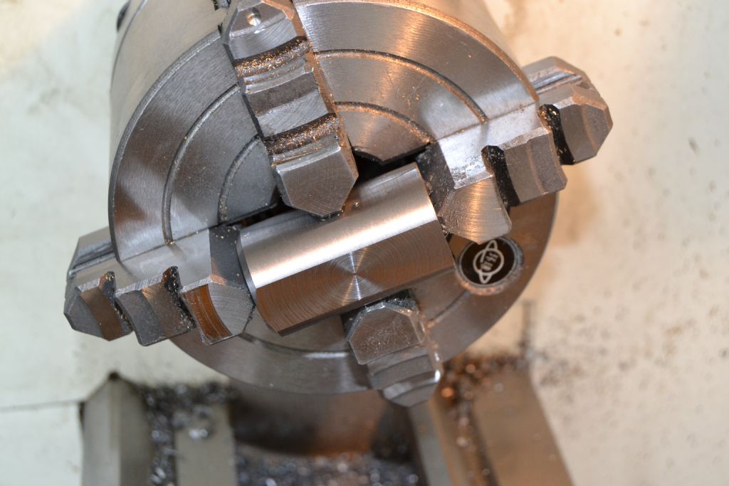
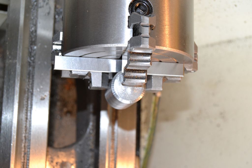
                                                      Trying to machine 2 parallel flat surfaces in the lathe by facing off with the work across the chuck proved to be the killer blow and I ended up with this.

                                                      steamer 9 (16).jpg

                                                      I decided the best thing was to have a few beers, sleep on it and try a different approach tomorrow.

                                                      Second time round I thought I'd try to machine the 2 parallel faces first (after truing the diameter and facing the ends). The first face seemed to look ok, visually at least.

                                                      steamer 9 (26).jpg

                                                      steamer 9 (27).jpg

                                                      I took far more time and care aligning the work this time, whilst saying to myself 1000 times 'I must not leave my parallels in the chuck'.

                                                      steamer 9 (32).jpg

                                                      steamer 9 (34).jpg

                                                      First impressions suggest 2nd face looks ok.

                                                      steamer 9 (36).jpg

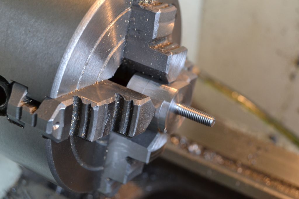
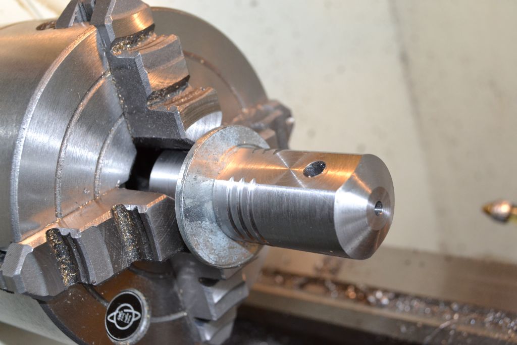
                                                      Yesterdays bodged attempt came in useful as a temporary threaded arbour to hold the work whilst I finish turned the diameter, cut a few decorative grooves and cut a taper for the top.

                                                      I also decided at this point to drill a small oil hole from the top to meet the axle hole. I'm not sure this will be necessary but it will give an excuse to top it off with a small knurled nut which will be a bit of added decoration if nothing else.

                                                      steamer 9 (43).jpg

                                                      steamer 9 (48).jpg

                                                      It's not perfect but I'm happy with the result.

                                                      steamer 9 (49).jpg

                                                      Not yet fixed down and there is still a bit to come off the crank pin and axle but it's beginning to take shape.

                                                      steamer 9 (54).jpg

                                                      steamer 9 (55).jpg

                                                      Peter.

                                                    Viewing 25 posts - 1 through 25 (of 66 total)
                                                    • Please log in to reply to this topic. Registering is free and easy using the links on the menu at the top of this page.

                                                    Advert

                                                    Latest Replies

                                                    Viewing 25 topics - 1 through 25 (of 25 total)
                                                    Viewing 25 topics - 1 through 25 (of 25 total)

                                                    View full reply list.

                                                    Advert

                                                    Newsletter Sign-up