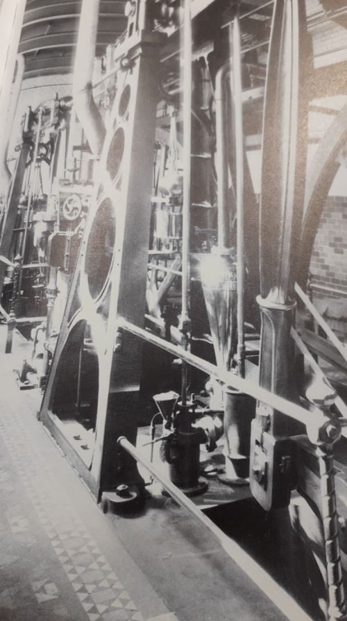
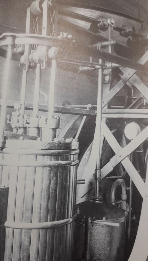
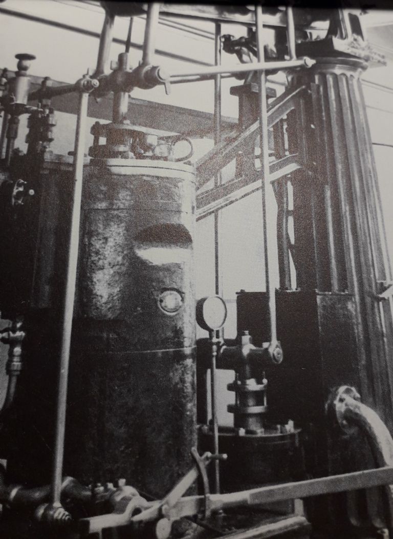
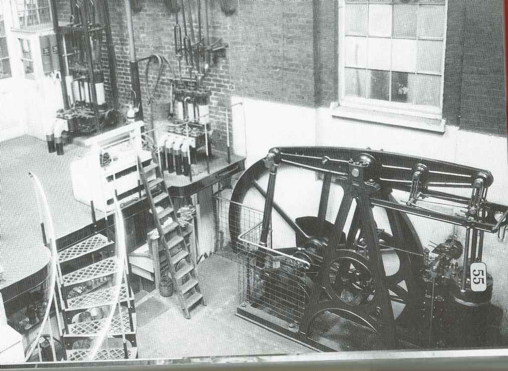
I am playing with some castings for the Vulcan Beam Engine, described by E.T.Westbury M.E. vols 111/2 1954/5.
It is not a model of a specific prototype but rather "a characteristic design based on early 19th century practice" using an engraving dated 1847 as inspiration.
My question is; how are the pumps placed relative to each other and the beam when there is more than one pump?
Background:
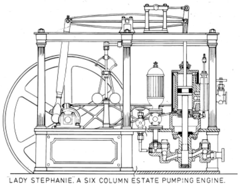
As drawn the engine is non-condensing and has a single boiler feed-pump driven from a boss located on the flywheel side of the beam-fulcrum. However, Mr Westbury writes that the engine can be converted to a representation of a condensing engine by the fitting of a second pump which he describes as being similar to the boiler feed pump, except twice the diameter. However he gives no clues as to how and where this second pump would be fitted.
I have only been able to find a single photo reference albeit in video form showing a two pump version of 'Vulcan' and in this case the two pumps are located side by side on a line at right angles to the beam using the single pump driving boss on the beam. The pumps are therefore offset from the beam, one to the left, and one to the right, and adjacent to each-other. Would that have been prototypical?
Nota: I am not in any way criticising this model, but am curious as I have no knowledge whatsoever of beam engine practice. Prototype drawings of the period (1830's?) that I have found appear to show pumps driven directly from the beam with one boss and driving rod per pump, one drawing even seemingly showing a pump driven from the lower links of the parallel motion nearest the beam fulcrum point.
So……
Would multiple pumps have been driven from separate individual bosses on the beam and so placed in-line immediately beneath the axis of the beam?
And, if so, ….. what would their probable disposition have been?
Placing the 'second' pump the same distance from the beam fulcrum but on the other-side (piston end) of the beam fulcrum from the first pump may conflict with the valve-gear rocking shaft, but could probably be overcome. That side is already very 'busy' however with parallel motion and valve-gear.
Placing the second pump on the same (flywheel) side of the beam as the boiler feed pump but further from the beam fulcrum (and if so…. by how much?) would increase the stroke, but this may allow a reduction in the proposed diameter. Or, when Mr Westbury wrote to double the diameter of the second pump did he perhaps anticipate it being fitted between the boiler feed pump and the fulcrum, thus having a shorter stroke?
To add more confusion to the issue Westbury further mentions additional pumps driven from the engine, for example to supply service water to the industry, and injection or hotwell (for condensing engines) as well. However he gives no clues as to location, sizes, etc., assuming a familiarity with the disposition of these items on the part of any constructor. A familiarity sadly lacking in my case!
But, perhaps you know how at least the two pumps, boiler feed and condensing, were probably arranged and can advise?
Regards,
Phil
Weary.


