Basic Clock Design

Advert

Basic Clock Design

Home Forums Clocks and Scientific Instruments Basic Clock Design

Viewing 25 posts - 101 through 125 (of 331 total)
  • Author
    Posts
  • #235427
    roy entwistle
    Participant
      @royentwistle24699

      I think that the idea of moving the weight line away from the pendulum is to stop the weight and pendulum swinging together in sympathy as they both reach the same length This can be detrimental to the stability of the clock itself Please don't ask me to explain I just know it can happen

      Roy

      Advert
      #235445
      Ajohnw
      Participant
        @ajohnw51620
        Posted by Russell Eberhardt on 20/04/2016 15:03:34:

        Posted by Martin Kyte on 20/04/2016 14:31:07:

        I cannot help thinking we are getting a little overcomplicated

        Quite!

        Just a minor point: Remontoire is French for a device that re-ascends or re-lifts so perhaps it is more correctly applied to a rewinding device than a force regulator. But then our use of non English terms is often at variance with the original meaning.

        Russell

        Only mentioned as it was mentioned in this context earlier.

        John

        #235466
        Russell Eberhardt
        Participant
          @russelleberhardt48058
          Posted by roy entwistle on 20/04/2016 15:37:25:

          I think that the idea of moving the weight line away from the pendulum is to stop the weight and pendulum swinging together in sympathy as they both reach the same length This can be detrimental to the stability of the clock itself Please don't ask me to explain I just know it can happen

          Roy

          I think the main reason is appearance. It's nice to see the full swing of the pendulum.

          Of course the weight can swing in sympathy with the pendulum as a result of mechanical coupling between the two. The usual cause is slight movement of the frame or the case with the pendulum swing giving coupling. I think of it as analagous to coupling between two electrical tuned circuits which gives a broadening of the frequency response and thus greater variation in timing. In extreme cases it can cause the clock to stop when the weight reaches the pendulum length as it absorbs energy from the pendulum.

          Russell.

          #235481
          John Haine
          Participant
            @johnhaine32865

            Now this is an interesting phenomenon. A guy called Ned Bigelow* in the US has made a 2-pendulum clock where only one pendulum is impulsed by the escapement and is closely coupled to the second, identical one, by hanging both of them from a supporting beam that is suspended by short tapes. This means the pendula can happily swing in anti-phase, and they do, balancing out each-others' forces on the beam. This sort of an extreme example of the swinging weight problem, so if the 2-pendulum clock works, why does the swinging weight stop the clock?

            (*And actually there are other examples made e.g. by a Swiss clockmaker.)

            As someone said, we are getting a bit away from the topic of "basic clocks" – maybe we need a new thread on "Horological Curiosities"?

            Edited By John Haine on 20/04/2016 21:59:18

            #235484
            Michael Gilligan
            Participant
              @michaelgilligan61133
              Posted by John Haine on 20/04/2016 21:58:25:

              … so if the 2-pendulum clock works, why does the swinging weight stop the clock?

              .

              … Because the swinging weight is not a closely matched, High Q, pendulum. It's resonance is 'broad' and it therefore acts more in mode of a tuned damper.

              MichaelG.

              .

              P.S. Huygens was [I believe] the first to notice that sympthetic vibrations would synchronise a pair of pendulum clocks … and the phenomenon has been discussed ever-since. [Plenty to choose from, here]

              Edited By Michael Gilligan on 20/04/2016 22:25:30

              #235487
              Ajohnw
              Participant
                @ajohnw51620

                If it's going in a case it would be possible to use a pulley to move it to the side and get more drop.

                Isolation by mounting the pendulum on a fairly hefty back plate as per usual.

                John

                Edited By Ajohnw on 20/04/2016 23:12:23

                #235491
                julian atkins
                Participant
                  @julianatkins58923

                  Can we please drop the remontoire stuff.

                  It has no place on the subject of basic clock design, and does not help James at all.

                  Cheers,

                  Julian

                  #235493
                  Ajohnw
                  Participant
                    @ajohnw51620
                    Posted by julian atkins on 20/04/2016 23:10:47:

                    Can we please drop the remontoire stuff.

                    It has no place on the subject of basic clock design, and does not help James at all.

                    Cheers,

                    Julian

                    The only reason they cropped up again was to correct something that could be taken the wrong way earlier Julian. As I thinks some on else expanded on as well.

                    I could pass another pretty obvious comment as well but wont. Why bring them up again for instance but there are others. In terms of the thread there was no point me posting this either.

                    John

                    -.

                    #235498
                    Michael Gilligan
                    Participant
                      @michaelgilligan61133

                      My parting thought, Julian, is a rhetorical question:

                      What do we mean by 'basic clock design' ?

                      If a "clock" doesn't keep time, then it is mere decoration … a shiny motor and gearbox that serves no useful purpose.

                      To my mind; a 'basic clock' is the simplest possible construct that keeps good time.

                      MichaelG.

                      #235508
                      James Alford
                      Participant
                        @jamesalford67616

                        Thank you for all of the replies, observations and suggestions. I need to read them in detail and study some of the links, but I do have a few questions or comments based on them.

                        Pendulum and Weight in Line

                        I can see how this could cause problems with the pendulum setting the weight off swinging as well. I had originally planned to use a spring drive, which would not have had the same concern. I shall look at changing the layout to off-set the weight.

                        Plate or Frame Design

                        There have been some helpful comments about mounting the frame and the limitations of the design as shown. The frames are only representative at this stage, not the final shape, and I shall take into account the points that have been raised.

                        Escapement Teeth Spanned

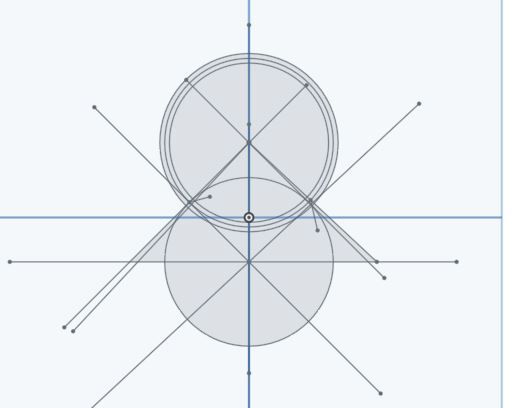
                        I designed the pallets and escape wheel using the method shown below, which I found in a various forms in different places. The two short lines near the horizontal line and either side of it are the start of the pallets. Why is it better to span more teeth than this?

                        basis for escapement.jpg


                        Remontoires and Maintaining Power Devices

                        I can see the benefits of these and shall mull them over. I have a commercial long-case clock that has nothing of this sort and it keeps reasonable time, but can see how these devices could improve it.

                        Tooth Count

                        Someone commented that using an 11 tooth pinion is not a nice number: there is no 11 tooth pinion in the train. The same post mentions that a 10 tooth pinion is a bad choice. Why?

                        The Book in the Archive

                        Thank you for this link. I have started to read it and bits look useful.

                        Regards,


                        James.

                        Edited By James Alford on 21/04/2016 07:19:10

                        #235511
                        jaCK Hobson
                        Participant
                          @jackhobson50760
                          Posted by jaCK Hobson on 14/04/2016 09:35:59:

                          I hate that when people tell me to shut up.


                          It's a discussion forum open to the internet. I'd have though free discussion would want to be encouraged. Some of the most interesting discussions wander away from the original topic. 

                          My mind has been changed by Michael and John and thank them for it and I'd like more. I don't think the OP is overly precious about keeping this 'his thread'. I know there have been threads where we've had to tread carefully in the past, but personally I like forums that encourage freedom of discussion. However, I'd be disappointed if this thread turns into a discussion about forum ethics and etiquette – and I'd be responsible I think the intention of the most knowledgeable people here is to point out that remontoires are an advanced device and not usually part of a basic design, but a similar concept may have a place for winding the weight as a space saving device.


                          btw: I do not include myself in the  "most knowledgeable" group but I do hold the above opinion. 

                          Edited By jaCK Hobson on 21/04/2016 08:16:51

                          #235515
                          John Haine
                          Participant
                            @johnhaine32865

                            James, on the question of "pendulum and weight in line" – coupling between the weight and the pendulum will happen however they are configured. When the pendulum is off-centre in its swing, gravity is exerting a sideways restoring force on the bob, and there is an equal and opposite sideways force on the pivot, which will try to "swing the clock". If the clock is not rigidly mounted, it will move slightly, and this generates a sideways force on the weight, whereever the weight is hanging from on the clock. This will also move the weight, and if the period of the weight on its cord is near the pendulum period an oscillation builds up and couples energy from the pendulum into the weight (though the mechanism has some interesting complexities). On a longcase 8-day clock, with seconds pendulum, weight on a single cord, if it's wound on a Sunday this will tend to happen on Thursday, so it's sometimes called the Thursday Effect or Disease. You can't avoid this just by not having them "in line" – actually they are always in line in some plane or other.

                            Two obvious ways to avoid it. One is to make sure the mounting is rigid, for example screw the clock to a solid wall. The other is to fit a single pulley on top of the weight, and double its weight, then lead the cord from the barrel round the pulley then back up and tie off to a pillar. This halves its drop so the weight line never gets long enough to cause a problem.

                            In principle there is another way, which is to balance out the reaction force from the pendulum by an identical but un-driven pendulum hanging symmetrically from the frame, which is deliberately caused to oscillate sympathetically with the driven pendulum through the coupling. The example of Bigelow's clock shows this is possible. I guess this may not qualify as a "basic" technique, but if you can make one pendulum another should present no problem. We don't have to keep making clocks, even basic ones, the way they have always been made!

                            #235522
                            Martin Kyte
                            Participant
                              @martinkyte99762

                              Just to clear up the point with Russell.

                              "Remontoire is French for a device that re-ascends or re-lifts so perhaps it is more correctly applied to a rewinding device than a force regulator. But then our use of non English terms is often at variance with the original meaning."

                              Yes it is a rewinding device but specifically in clockmaking is applied to a device that rewinds a small spring in the power train of a clock at very frequent intervals in order to keep the tension in that spring as constant as possible and it's application is as a force regulator which isolates the escapement from the varying force of the primary power source be it weight or spring driven and the frictional forces in the train.

                              It is not really at variance with the original meaning but it has a more restricted and well defined meaning in clockmaking. Endless rope systems are generally termed automatic rewinding mechanisms to avoid the confusion.

                              In relationship to the relative "precision" of the clock the requirements can be found by observation. If you are happy with the accuracy of a long-case clock all you need is weight driven power source, anchor escapement and for it to be well made.

                              If you want something that handles temperature changes better without too much variation in rate then use in order of complexity and invar pendulum rod, same with the bob suspended by its midpoint, Gridiron rod or zinc iron compensation.

                              With regard to the clock plates as shown you are likely to be unable to stop things swinging around. The Claude Reeve 'regulator' was pretty flimsy in the same way. Much better to go for wide clock plates with decent sized pillars separating the plates. Regulators and big tower clocks can be arranged so that the pendulum suspension is attached to the wall but that again is overkill for what you want. You do need to make arrangements for mounting the clock in it's case and for mounding the dial plate. Wide clock plates make this simpler too.

                              regards Martin

                              #235528
                              speelwerk
                              Participant
                                @speelwerk

                                Posted by James Alford on 21/04/2016 07:14:28:

                                Someone commented that using an 11 tooth pinion is not a nice number: there is no 11 tooth pinion in the train. The same post mentions that a 10 tooth pinion is a bad choice. Why?

                                When using a 10 tooth pinion with an 80 tooth wheel makes that any (dividing) error in the wheelwork stays at the same place with every revolution the wheelwork makes. If you would use a 10 tooth pinion with a 79 or 81 tooth wheel any error is spread over all the teeth. Niko.

                                #235540
                                Martin Kyte
                                Participant
                                  @martinkyte99762

                                  Oh and if you put the pinions on the opposite ends of the arbors as the wheels so the drive alternates from one side of the clock to the other you will even out the loading on the pivots better. (I'm sure you realised that really and you were just doing sketch mock up's)

                                  You could have a think about putting the great wheel arbor on bearing races rather than plain bearings but that's more valid for spring driven clocks as you can always use a bigger 'lump' in a weight driven clock.

                                  The other main thing is stop thinking like a normal engineer when clock making. The pivot fits should be loose. Not sloppy but loose. The old adage if it rattles it will run generally holds true. Backlash is irrelevant all wheels drive in the same direction and are always under power, what you don't want is tight spots.

                                  Make a good rigid frame.

                                  Remember that the designs for clocks over the years have evolved for good reason so IF you want to change things have a very good reason for doing so. There is plenty of scope for your own elegance without altering the essential designs too much.

                                  Happy clockmaking.

                                  #235559
                                  Ajohnw
                                  Participant
                                    @ajohnw51620

                                    The tooth count enclosed by the escapement is I suspect something that has been found to work out well over time. 7 1/2 teeth and a 2 degree pendulum swing seems to be pretty standard. Several things come in to it which are explained in that old book I linked to. Lift for one – how much clearance there is when it lifts. It's only a few pages to read.

                                    Penman's book, Practical Clock Escapements shows varying tooth counts but as soon as he gets to regulators with 30 tooth escape wheels it might be described as 8 tooth pitches. In other words one pallet is directly above a tooth tip as he draws them. He also reckons regulators typically have 3 degrees pendulum swing. The old book is American.

                                    I did explain the pinion tooth count debate but perhaps not clearly enough. The argument goes that when an 8 tooth pinion is used only 1 tooth is ever engaged, the minimum tooth count to get 2 engaged at the same time is 11, not nice so people use 12. More can be used if appropriate in order to get some particular ratio. Most clocks I have been in the back of use the lower numbers. The argument hinges around accuracy really but when run in 2 teeth working at the same time with the same load as 1 should reduce friction and give smoother operation.

                                    On even cheaper old wall pendulum clocks the pendulum is usually isolated by mounting it on a hefty back plate. The movement is also mounted on that and all that connects the two is something akin to a thin piece of bent wire to transfer the impulses to the pendulum. All sorts of things creep into this area on higher end clocks mostly to set the beat but the coupling still needs to be weak. That end tends to be cost more than I am prepared to pay but I am embarrassed by how many cheaper clocks I have bought over the years, and movements.
                                    I'd say that if some one doesn't want to use plates which will tend to hide all of the work that is been done that the Burgess arrangement may be of interest. It has it's back plate and putting it simply the movement is mounted on that as a series of sub assemblies. The 2 design book I mentioned has cut outs in the plate on one of the designs.

                                    Mantle clocks etc I have seen do have the pendulum mounted on the movement but the pendulum is shorter and much much lighter. Most seems to use much larger swings than regulators. One American clock I had must have been more like 20+.

                                    I've been out for 2 1/2 hrs since starting this so no idea what others have posted.

                                    John

                                    #235574
                                    Ajohnw
                                    Participant
                                      @ajohnw51620

                                      Glad you like the book James. It's one of the clearest I have seen. As always though opinion will come into it.

                                      For some one starting from scratch this thread might be useful. Not down to exactly what he is doing but how he went about it as it was a journey into the unknown.

                                      **LINK**

                                      John

                                      #235607
                                      Ajohnw
                                      Participant
                                        @ajohnw51620

                                        This should be useful and also shows what I meant about the teeth spanned by a dead beat escapement. No half but almost 8 teeth, just a bit short but it can be set to other numbers.

                                        **LINK**

                                        However I did have one clock where the ends of those lovely sharp teeth were bent over. It seems to me that the drop could be increased as far as the sums are concerned and then corrected when the wheel it cut by moving that flank back leaving a bit of a blunt end.

                                        The default numbers in it seem to be typical. Working closer needs higher precision work.

                                        John

                                        #235672
                                        James Alford
                                        Participant
                                          @jamesalford67616

                                          Thank you for all of the replies, which I shall study and take into account as I work on the plans.

                                          Regards,

                                          James.

                                          #235954
                                          James Alford
                                          Participant
                                            @jamesalford67616

                                            I have modified my gear train in light of the suggestions made and am now trying to work out how long the clock is likely to run for as it stands. Assuming a drop of four feet, I come up with a running time of about three days.

                                            I have been thinking about how to increase this duration and have come up with:

                                            Raise the clock to increase the drop

                                            Possible, but not going to make a huge difference.

                                            Increase tooth count on the driving wheel

                                            Difficult due to size restrictions of my lathe. The maximum comfortable diameter is four inches.

                                            Reduce tooth count on the driven pinion

                                            Possible, although I am trying to avoid really small pinions due to their fiddly nature. I have looked for the ready cut lengths that someone previously mentioned, but cannot find any.

                                            Introduce another gear into the motion between the driving gear and the next wheel

                                            This seems to be the most feasible option.

                                            Some sort of rewinder

                                            Not sure,

                                            Have I missed an obvious method? I have looked at ways of looping the rope or chain over other pulleys, but I still come back to the limitation of the drop.

                                            I should appreciate any suggestions.

                                            Thank you.

                                            James.

                                            #235959
                                            Russell Eberhardt
                                            Participant
                                              @russelleberhardt48058

                                              1. Suspend the driving weight from a pulley and fix the cord at the top, loop it round the pulley and back up to the barrel.

                                              2. Reduce the diameter of the barrell.

                                              3. Mount the clock higher.

                                              4. Change the gear ratios.

                                              Russell.

                                              Edited By Russell Eberhardt on 24/04/2016 11:06:39

                                              Damn! can't seem to delete duplicated postsad

                                              Edited By Russell Eberhardt on 24/04/2016 11:08:37

                                              #235961
                                              Russell Eberhardt
                                              Participant
                                                @russelleberhardt48058

                                                1. Suspend the driving weight from a pulley and fix the cord at the top, loop it round the pulley and back up to the barrel.

                                                2. Reduce the diameter of the barrell.

                                                3. Mount the clock higher.

                                                4. Change the gear ratios.

                                                Normally a drop of about 1 m is required for an 8 day long case clock with the pulley arrangement as 1.

                                                Russell.

                                                #235987
                                                James Alford
                                                Participant
                                                  @jamesalford67616

                                                  Russell,

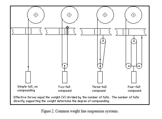
                                                  Thank you. Do you mean a bit like the second example in following picture for the looping? If so, I am being really dense as I do not see how it increases the effective fall. I can see how it will require a heavier weight due to the compunding effect, but not the running time.

                                                  capture.jpg

                                                  #236030
                                                  Russell Eberhardt
                                                  Participant
                                                    @russelleberhardt48058

                                                    Yes, the second example. If the weight drops one foot the total length of cord is extended by two foot hence the running time is doubled for the same drop. Of course the barrel has to be able to accomodate twice as much cord.

                                                    Russell.

                                                    #236031
                                                    Russell Eberhardt
                                                    Participant
                                                      @russelleberhardt48058

                                                      This one, recently completed runs for 32 days with a one metre weight drop:

                                                      dscf2667sml.jpg

                                                      Just the case to finish now.

                                                      Russell.

                                                    Viewing 25 posts - 101 through 125 (of 331 total)
                                                    • Please log in to reply to this topic. Registering is free and easy using the links on the menu at the top of this page.

                                                    Advert

                                                    Latest Replies

                                                    Viewing 25 topics - 1 through 25 (of 25 total)
                                                    Viewing 25 topics - 1 through 25 (of 25 total)

                                                    View full reply list.

                                                    Advert

                                                    Newsletter Sign-up