Basic Clock Design

Advert

Basic Clock Design

Home Forums Clocks and Scientific Instruments Basic Clock Design

Viewing 25 posts - 301 through 325 (of 331 total)
  • Author
    Posts
  • #239649
    Russell Eberhardt
    Participant
      @russelleberhardt48058

      O.K. In the common case that the working faces of the escape wheel are truly radial (unlike James' drawing) the tangents to the circle at the locking point meet at the pivot point of the pallet frame. Thus, for small movements of the pallets they slide along the tooth face with no movement of the tooth (dead beat). They are perpendicular to the working face of the tooth.

      Sometimes it is convenient to move the pivot point closer to the wheel and the tooth can be undercut to maintain that perpendicular. In that case the lines drawn are, of course, no longer tangents.

      John, Whatever the angle of the tooth it will be parallel to a diameter of the wheel. Was there a particular diameter line you were thinking of?

      Russell.

      Advert
      #239778
      Ajohnw
      Participant
        @ajohnw51620

        The last drawing I posted Russell showing tangents either side of the pallet according to either an odd or even number of teeth being spanned.

        They are drawn on the basis of being offset by 1/4 or the tooth pitch and I assume that the tooth flanks are parallel to them BUT am rather unsure. The book I have isn't clear but if they aren't to set the flank angle there doesn't seem to be any point in drawing them.

        I've been bogged down with clearing a garage and out buildings ready for a new roof for them. 2 maxi skips filled so haven't had chance to try any drawings yet. Moving a car with rusty brakes wasn't much fun either. It hasn't moved for 15 years.
        John

        #239935
        Russell Eberhardt
        Participant
          @russelleberhardt48058
          Posted by Ajohnw on 22/05/2016 17:34:34:

          The last drawing I posted Russell showing tangents either side of the pallet according to either an odd or even number of teeth being spanned.

          I'm a bit confused. The lines on that drawing labelled as tangents don't seem to be tangential to anything??

          The tangents I was referring to are tangents to the pitch diameter circle and are thus perpendicular to the tooth flanks when those flanks are radial. They meet at the pallet frame axis.

          Good luck with the garage clearance.

          Russell.

          #239967
          Ajohnw
          Participant
            @ajohnw51620

            Me confused too Russell. I'd suspect the only way to sort it is to draw both pallets at lock and see what the best angle is for both and take some sort of average.

            John

            #239995
            James Alford
            Participant
              @jamesalford67616

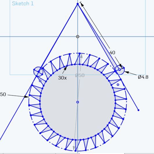
              Thank you for the ongoing advice, suggestions and comments, which I have been reading and trying to apply. Below are two pictures of my latest version. A few key details:

              • The functioning portion of the pallet is half of the diameter of the pallet less half of the drop
              • The operating faces of the teeth are a smidgen under 90 degrees to the tangent drawn from the pivot point of the pallet arms to the OD circle of the escape wheel.
              • There are 30 teeth on the wheel.
              • The wheel is 50mm OD
              • The pallet arms are 40mm long.

              I think that, unless it is clear that I have made a glaring mistake somewhere, the next step would be to construct a test version.

              revised brocot - full.jpg


              revised brocot - detail.jpg

              Regards,

              James.

              Edited By James Alford on 24/05/2016 08:06:09

              Edited By James Alford on 24/05/2016 08:07:01

              #240004
              Ajohnw
              Participant
                @ajohnw51620

                You could study the active tooth face flank by drawing an arc from the pivot just touching the left hand pallet where it's up against the tooth locking the wheel. That's the path the pallet will follow when the pendulum carries on swinging after the impulse.

                John

                Edited By Ajohnw on 24/05/2016 09:48:46

                #240018
                Russell Eberhardt
                Participant
                  @russelleberhardt48058

                  That should work James. Any slight errors can be corrected by rotating the pallets slightly.

                  Russell.

                  #240128
                  James Alford
                  Participant
                    @jamesalford67616

                    Thank you for the feedback. I shall leave this part of the overall clock design as it is for now and make small changes and adjustments once I have actually started to build it. I shall now move onto other parts of the design.

                    Regards,

                    James.

                    #240130
                    Ajohnw
                    Participant
                      @ajohnw51620

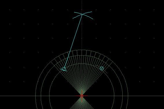
                      I've made a start at drawing one. 60 tooth, 2.25mm dia pallets. 2 degree impulse angle I've allowed 2.35 for drop. No teeth yet but the long radial lines are for the flanks and the short ones 1/2 the tooth angle.

                      The whole drawing

                      brocotdrgcad.jpg

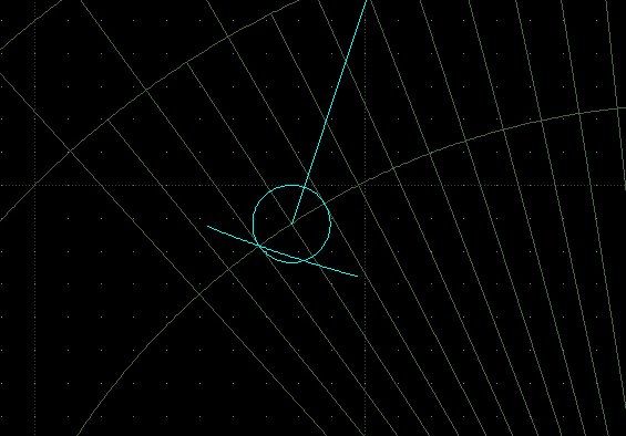
                      An enlargement of the left pallet at lock with a rad showing it's path as the pendulum swings further after an impulse.

                      brocotdrgcad.v01.jpg

                      The rad is not far of a straight line. Yet to find out how to get an angle out of the cad package and haven't got me head round what it will look like when the other pallet is at lock – pendulum swinging the other way. Suspect I will draw it again. I saved the angled rays separately 'cause they took a while to do.

                      To construct it I put the pallets where they should be ( I hope ) and then worked out from the pallet diameter the pivot needed to be to get the impulse angle. Then struck that as arcs off the centre of both pallets. It should save trying to rotate the wheel but results in the pivot being slightly off 90 degrees to the wheel.

                      I worked out what the rad of the locking pallet should be and drew that so that I could lock the pallets to the intersect of the rad and the 1/2 tooth pitch angles.

                      John

                      Edited By Ajohnw on 24/05/2016 22:17:51

                      #240137
                      Ajohnw
                      Participant
                        @ajohnw51620

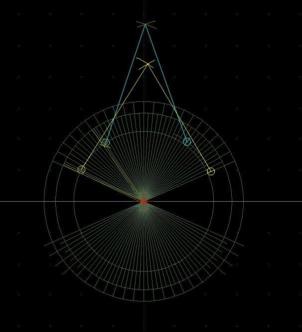
                        I add a 1/2 pallet diameter circle to see what the flank looked like parallel to to a tangent from the centre of the wheel to that circle. That's in dark yellow. I also added a rad showing where the extremities of the pallet go when the pendulum continues to swing.

                        brocotdrgcad.v02large.jpg

                        surprise The flank at that angle looks about right to me. It's not far off radial. Any thoughts?

                        I'm using LibreCAD. I tried the other I mentioned but it got upset adding constraints to all of those lines at an angle. It is an easy to use package though. LibreCAD isn't looking too bad in that respect either. One minor problem. When I had the reference point on the centre of the wheel I should have clicked Lock Relative Zero to stop it moving that style of reference around when ever I drew anything. When it's off the reference becomes the end of the last thing drawn which is how these packages are often used.

                        Actually the faint dark brown should be dark yellow but I doubt if the package picks up my unusual colour management correctly so may not display correctly here.

                        Should have drawn the arcs in that too. Easy to fix, select, hit delete and draw them on the correct layer.

                        In this case the flank angle is 1.5 degrees of radial.

                        John

                        Edited By Ajohnw on 24/05/2016 23:32:06

                        Edited By Ajohnw on 24/05/2016 23:42:47

                        #240230
                        Ajohnw
                        Participant
                          @ajohnw51620

                          Just tried drawing in a larger tooth span.

                          brocotallbiggerspan.jpg

                          The flank angle stops the same. As it should done this way. Just checking.

                          I haven't worried too much about the tooth span on these. blush I think it's an odd number but it would be a lot clearer if the teeth were drawn in. So next job. Currently LibreCAD can't repeat shapes at angle or holes in a circle unless I am missing something. Other than that I'm pretty impressed with it. The various snapping options work well and the ability to snap on points and set sizes with a mix of mouse or typed in numbers is useful.

                          devil I have a feeling that I will span near 180 degrees. Do it again now and check my calc of the wheel dia as it looks like it's slightly in error. I'd allowed 0.1mm lock and no level of zoom shows it. Could be down to line thickness but more likely me.

                          John

                          #240352
                          James Alford
                          Participant
                            @jamesalford67616

                            It is interesting to see someone else's drawings and design steps to achieve the same result. I shall keep reading

                            James.

                            #240356
                            Ajohnw
                            Participant
                              @ajohnw51620

                              It seems that LibreCAD has a copy and rotate n times facility which would make the drawings I have done so far a lot easier. So it can do pcd's etc.

                              John

                              #257493
                              Michael Gilligan
                              Participant
                                @michaelgilligan61133
                                Posted by Michael Gilligan on 11/04/2016 08:51:03:

                                If the overall construction is to be light, then an electrically wound remontoire might be the answer.

                                .

                                Just returning to this point:

                                It's a bit like watching paint dry, but the animation in this video [which lasts 15 miutes] is worth a brief look.

                                MichaelG.

                                #257591
                                James Alford
                                Participant
                                  @jamesalford67616

                                  Michael,

                                  Thank you for this link, which is the clearest and simplest explanation of a remontoire that I have seen.

                                  I am still working on a design, although for a variety of reasons, I have moved towards an electrically impulsed pendulum, rather than a weight-driven design.

                                  I shall post some pictures once the design is finished.

                                  Regards,

                                  James.

                                  #257636
                                  Ajohnw
                                  Participant
                                    @ajohnw51620

                                    Nice video Michael. Me and clocks are on the shelf until my work area is sorted out. It's moving slowly.

                                    I've spend some times getting to grips with some of the things Harrison used to get up to. It makes weight driven remontoires attractive.

                                    Designs vary but don't generally maintain accurate timing. The error can be centred around perfection so that through one part of the cycle they loose and through the other part gain cancelling each other out. This then leads to rather short re energisation periods so that the variations are small and also maybe directly applying it to the escapement to keep the loading on it low. That in turn means a lot of attention to masses and friction.

                                    indecisionLeaving the problem just how to drive it with power levels that don't need a lot of battery. I suspect that aspect also applies to electrically impulsing the pendulum as well going on a design I have seen.

                                    blushI do have my length of carbon fibre tube for the rod and a selection of ball races. I decided well cleaned out stainless bearings are probably best for this sort of thing probably well blown up to speed with an air line. It does seem that there are better materials for supporting a pendulum bearing but it's hard to be sure.

                                    John

                                    #257639
                                    Russell Eberhardt
                                    Participant
                                      @russelleberhardt48058
                                      Posted by Ajohnw on 24/09/2016 13:45:42:

                                      blushI do have my length of carbon fibre tube for the rod and a selection of ball races. I decided well cleaned out stainless bearings are probably best for this sort of thing probably well blown up to speed with an air line. It does seem that there are better materials for supporting a pendulum bearing but it's hard to be sure.

                                      I tested the stainless steel ball bearings for my regulator clock roughly by mounting them as supplied on an arbour and wheel, spinning it up, and timing how long it ran before stopping. The bearings cleaned in white spirit gave about five times as long to spin to a stop than those as supplied.

                                      #257681
                                      duncan webster 1
                                      Participant
                                        @duncanwebster1
                                        Posted by Russell Eberhardt on 24/09/2016 14:32:54:

                                        Posted by Ajohnw on 24/09/2016 13:45:42:

                                        blushI do have my length of carbon fibre tube for the rod and a selection of ball races. I decided well cleaned out stainless bearings are probably best for this sort of thing probably well blown up to speed with an air line. It does seem that there are better materials for supporting a pendulum bearing but it's hard to be sure.

                                        I tested the stainless steel ball bearings for my regulator clock roughly by mounting them as supplied on an arbour and wheel, spinning it up, and timing how long it ran before stopping. The bearings cleaned in white spirit gave about five times as long to spin to a stop than those as supplied.

                                        blowing bearings up to high speed with an airline is a good way of getting the solvent out, but it doesn't do the bearings any good. Running unloaded, unlubricated at very high speed isn't good for them. Nip the inner and outer races togther so they can't rotate and then use our air line by all means. I know we've all got away with it, but might as well do it right.

                                        #257904
                                        James Alford
                                        Participant
                                          @jamesalford67616

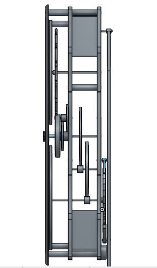
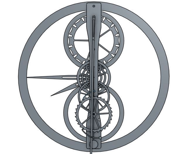
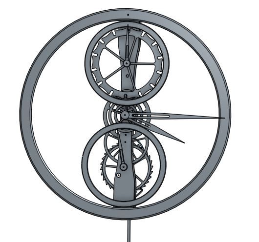
                                          After what seems like forever, I have finally finished a design for a clock powered by an electromagnetic solenoid and magnet.

                                          In the design, the batteries will sit in the box that is sandwiched between the frames at the top, whilst the circuitry to control the solenoid will be in the bottom box. The electromagnet sits between the rear plate, at the bottom, and the pendulum, with a magnet attached to the pendulum.

                                          I have found a circuit diagram for a comparator circuit that is designed to impulse the pendulum once its swing is below a certain point.

                                          The bottom of the three dials is a seconds hand, with the top dial, driven by a Geneva wheel, shows the days of the week, split into morning and afternoon.

                                          There is still some detailing to do: the pendulum rod is shown as a square section and it is shown suspended on a pivot rod; it will be a round rod and will probably get a conventional suspension.

                                          clock - side.jpgclock - rear.jpgclock - front.jpg

                                          Edited By James Alford on 26/09/2016 07:41:47

                                          #258420
                                          Michael Gilligan
                                          Participant
                                            @michaelgilligan61133

                                            For info.

                                            There is an interesting four-page article in the September 2016 issue of Horological Journal.

                                            "Wheels with Tapered Crossings" : Calculations for Aesthetics of Skeleton Clocks

                                            by Philip Kuchel of Sydney Clockmakers Society

                                            MichaelG.

                                            #258451
                                            Michael Gilligan
                                            Participant
                                              @michaelgilligan61133

                                              Forgot to mention … The September 'Article of the Month' [free download] may be of interest to forum members **LINK**

                                              http://bhi.co.uk/horological-journal/article-of-the-month/

                                              MichaelG.

                                              #258470
                                              Ajohnw
                                              Participant
                                                @ajohnw51620

                                                Neat idea James.

                                                John

                                                #258471
                                                Neil Wyatt
                                                Moderator
                                                  @neilwyatt
                                                  Posted by Michael Gilligan on 29/09/2016 13:29:13:

                                                  Forgot to mention … The September 'Article of the Month' [free download] may be of interest to forum members **LINK**

                                                  http://bhi.co.uk/horological-journal/article-of-the-month/

                                                  MichaelG.

                                                  Thanks for that.

                                                  Neil

                                                  #258719
                                                  Michael Gilligan
                                                  Participant
                                                    @michaelgilligan61133

                                                    October 2016 issue of HJ arrived today …

                                                    It include 3 articles that might be of technical interest:

                                                    1. Making a Barometric Compensator
                                                    2. A New, Very Fast Method for Computing Optimal Horological Gear Trains
                                                    3. Engine-Turned Watch and Cock Dials

                                                    MichaelG.

                                                    #258782
                                                    James Alford
                                                    Participant
                                                      @jamesalford67616
                                                      Posted by Michael Gilligan on 01/10/2016 14:32:23:

                                                      October 2016 issue of HJ arrived today …

                                                      Is this magazine available only to members or is it possible to buy individual copies anywhere?

                                                      Regards,

                                                      James.

                                                    Viewing 25 posts - 301 through 325 (of 331 total)
                                                    • Please log in to reply to this topic. Registering is free and easy using the links on the menu at the top of this page.

                                                    Advert

                                                    Latest Replies

                                                    Viewing 25 topics - 1 through 25 (of 25 total)
                                                    Viewing 25 topics - 1 through 25 (of 25 total)

                                                    View full reply list.

                                                    Advert

                                                    Newsletter Sign-up