I'd agree with Jason, and posit a vertical uniflow cylinder with a weighted piston as the simplest, although a more complex one could be made. Obviously such an engine would only run at a limited range of speed and pressure as it will rely on a certain resonance to work. If the piston is magnetic and the cylinder not, placing a coil nearby would allow it to do useful work, like a free-piston stirling generator.
With 3-d printing you could probably make a 1-part steam engine, that used a weighted flap as a 'piston and valve' (think a harmonica reed) altgough it might struggle to be 'viable'.
I can do 4 pieces and it might leak a little steam as I wouldn't waste my count with gaskets. Not counting the pipe delivering the air. Thinking about the 2 piece.
Rotary engine is a bit easier at 2 pieces.
Reminds me of the 'competitions' to write a computer program to wipe the memory and itself in as few instructions as possible.
Slightly different tack here but for a 2-stroke CI engine I reckon you could just about make do with 3 moving parts (crank, con rod and piston), possibly even 2 if you used a combined, one-piece spherical piston / rod. Fixed "carburettor", non adjustable compression ratio. Would be a pig to start and would be practically useless but for a bet it might be the simplest possible engine you could build. I expect someone's already thought of that though….
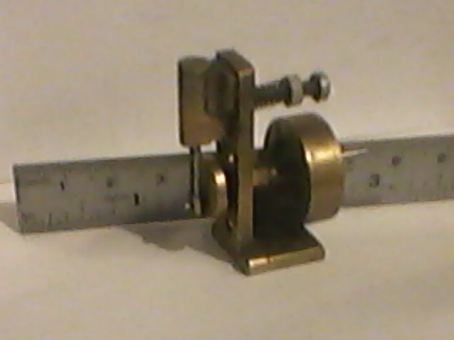
The little wobbler sitting on the desk has 14 individual parts, including the two pins on the flywheel that connect with the prop shaft on the boat it was built for. 3 mm bore x 6 mm stroke. Ian S C
I believe a truely viable engine can be made using a total of 6 parts. It would be a single acting uniflow engine with a Scotch yoke type crank and overhung crankshaft. The parts list would be:
Engine structure, including cylinder (the bore a blind hole), main bearing and guide for Scotch yoke. This would be a single casting in iron
Piston, cast iron
Guide pin for piston
Scotch yoke
Crankshaft with integral flywheel
Location pin for crank shaft.
I will endeavour to produce a sketch in the next few days.
I have a book on car maintenance from the '30s with an advert for a car with an engine with only 7 moving parts as a key feature. I think there is one of these cars in the Glasgow museum and the unusual 2 stroke engine has twin pistons with connected combustion chambers. Not sure where the book is to find the details.
Are we all agreed that as we mostly don't have foundries and can't afford to waste material machining from solid that eg a flywheel with pressed in shaft that could have been made as one item only counts as one?
I'm down to 3. Flywheel, body/cylinder, piston with built in uniflow porting (alternatively crankshaft porting which might be more reliable but complicates the body casting).
I promised a sketch showing my thoughts on this engine.
The structure is a single cast iron block with integral cylinder and main bearing. The cylinder is a deep blind hole with inlet and exhaust porting in the wall. The piston, a bit longer than the stroke, is cast iron with a tight running fit in the cylinder (similar to small two stroke I.C. engines). This should obviate the need for a piston ring. The steam enters and leaves the cylinder through passages in the piston that match cylinder wall porting at TDC and BDC. However it is unlikely that the engine will work if residual steam/water is trapped in the cylinder after the exhaust port closes (I suspect that a condenser would cure this problem but that would be way outside the design brief for this engine). Therefore the exhaust port is elongated and timed so that it remains open for most of the dead stroke. This is accomplished by a scroll milled into the surface of the piston mating with a guide pin held in the structure. This rotates the piston to allow the timing of the ports (I believe a similar scroll system was used in the Maxim Gun). If the cylinder was horizontal it would be wise to place the exhaust port at the bottom and leave it open to make the cylinder self draining.
A Scotch yoke is used solely to keep the number of parts to a minimum. It is located by the cylinder and side piece provided by the structure. To allow the piston to rotate the yoke has a cylindrical stud that engages with a tee slot cut in the piston. The yoke is machined from a block of bronze.
The yoke mates with the crankpin which is integral with the main shaft and flywheel. To allow the part to be slid through the structure as one piece the shaft diameter will have to be greater than the stroke plus the crankpin diameter. The part, made of steel, is held in place by a locating pin running in a groove cut in the shaft.
I believe the engine is viable with the following comments:
It will leak steam
I think the Scotch Yoke is quite simply a horrible mechanism
A good size flywheel is needed to take the piston through the dead stroke
The engine is not reversing and will have a fixed cut-off
It may need quite a bit of running in depending on the fit of the piston in the cylinder
The surface speed of the main shaft in the structure will be high and could be the limiting factor on engine speed
I have tried to keep the rubbing surfaces to cast iron on cast iron, cast iron on mild steel and bronze and bronze on mild steel. However I suspect the Scotch yoke will need lubricating frequently
Although there is a lot of machining the only difficult items will be the cylinder bore and the scroll in the piston.
After all that I suspect the next comment is “build it and see if it works”.
Twisty (a reinvention of an earlier engine also featured in ME) was pretty simple. A rod that serves as piton and valve reciprocates in a cylinder, with a flywheel operated by a peg in the cylinder shaft so the piston twists as it reciprocates.
Neil
Author
Posts
Viewing 17 posts - 1 through 17 (of 17 total)
Please log in to reply to this topic. Registering is free and easy using the links on the menu at the top of this page.