Banding on surface finish

Advert

Banding on surface finish

Home Forums Manual machine tools Banding on surface finish

Viewing 19 posts - 1 through 19 (of 19 total)
  • Author
    Posts
  • #116838
    M0BND
    Participant
      @m0bnd

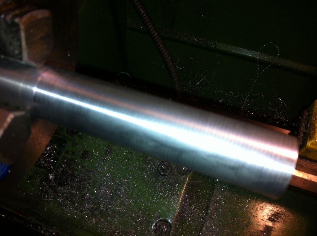
      Here you can see what I am getting….

      img_0968.jpg

      It is not good…
      The history of the lathe that I have is this. It was a 'bargain basement' purchase at a Warco open day around two years ago. This was sold to me with a story of another supplier selling lathes and offered to Warco – they declined as they have good relations with their current supplier and didn't carry on with the new supplier, this was the lathe that was left with Warco.
      I didn't use the lathe for some time (about 1 ~ 1.5 years) as not long after I took delivery of the lathe and mill I suffered with back problems. This meant I couldn't stoop down to use them. Now I am trying them all out and sorting out any issues which may or may not always come with this type of purchase.
      I have checked and tightened all gibs with little or no readings from my DTI on checking. The only reading I get is when I place a clock on the lathe chuck and lever underneath this and I get around 0.01 to 0.025mm deflection. I don't have a manual as such for the lathe so I am unsure of the allowable limits in the headstock bearings.
      The lathe is a FC3200 from RiPu manufacturing, I have tried to contact these and other suppliers of the same lathe about a manual, but don't get any replies. The lathe seems to be exactly the same as this one here – **LINK**

      Any advice or help would be greatfully received.

      Andy.

      Advert
      #12118
      M0BND
      Participant
        @m0bnd
        #116841
        Sub Mandrel
        Participant
          @submandrel

          Hi Andy,

          We see a lot of pictures like that on this forum.

          First check, is the spacing of the bands the same as the pitch of the leadscrew?

          Neil

          #116843
          M0BND
          Participant
            @m0bnd


            Neil.
            Extremely similar!! the width of the bands are 1.5mm pitch – not exactly the same but close enough.
            What are you thinking thinking?

            Andy.

            Jut seen the specs on my previous link….and I quote 'Pitches of three feed screws = 3mm'!!!!

            Edited By M0BND on 14/04/2013 12:35:14

            #116856
            Gray62
            Participant
              @gray62

              When you experience this 'banding effect' are you driving the saddle from the leadscrew or the feedshaft? as this will have a bearing on what is causing the poor surface finish.

              #116857
              M0BND
              Participant
                @m0bnd

                Why would the lead screw have anything to do with the finish? Surely it's the feed screw below that moves the saddle or cross slide?

                Andy.

                Coalburner – I must have posted at the same time!  Feedshaft is the answer.

                Edited By M0BND on 14/04/2013 13:45:14

                Edited By M0BND on 14/04/2013 13:46:22

                #116858
                Anonymous

                  Andy,

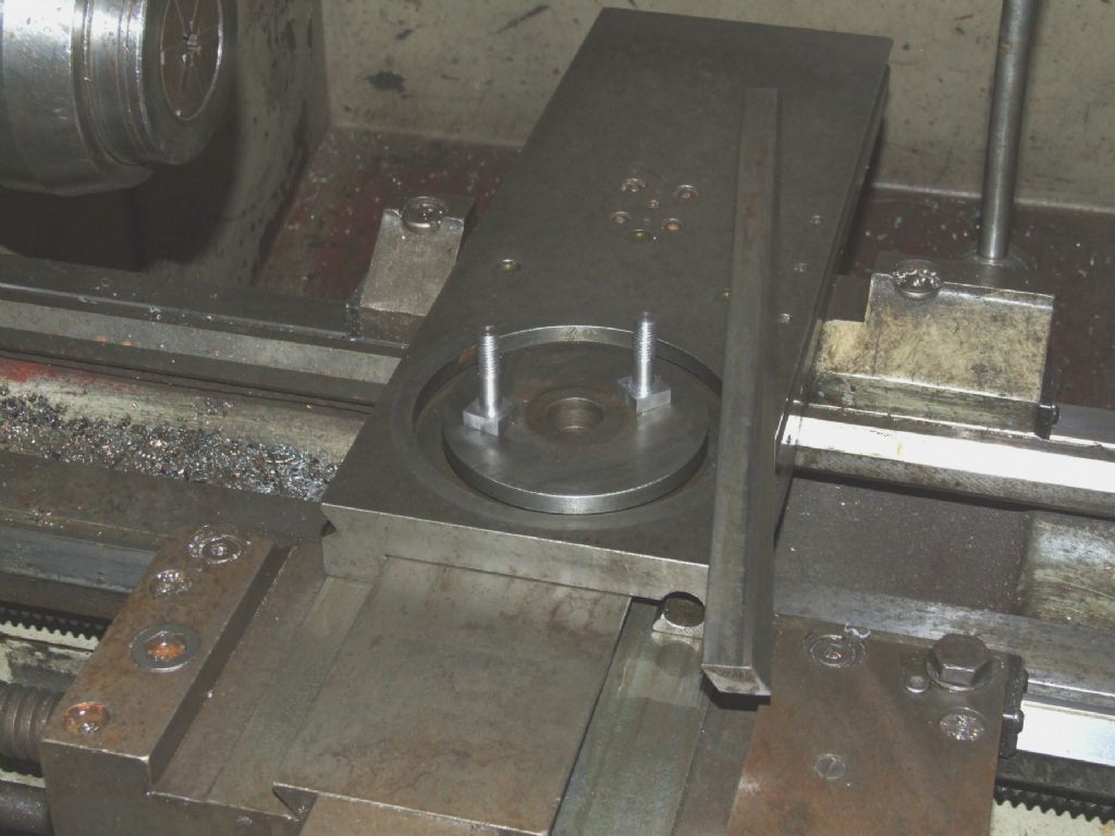
                  To follow up on your question in another thread; by worn bolt I mean that the threads were pretty much stripped, so the bolt wasn't doing much. Here's a picture of the banding I was getting on silver steel:

                  Silver Steel Banding

                  The banding was actually a multi-start 'thread', difficult to tell how many, but certainly around 6 to 8 start. There didn't seem to be any obvious correlation between spindle or motor speed. I run from a true three phase supply, so no issues with single phase motor vibration. My lathe has a dedicated power feed shaft, so no issues with the leadscrew either. Here's a picture of the new bolts:

                  T_Nuts

                  Getting the compound slide clamped down properly cured the banding problem.

                  Regards,

                  Andrew

                  #116867
                  M0BND
                  Participant
                    @m0bnd

                    Thanks for showing the photos Andrew.
                    I have spent the last hour or so stripping the top down, cleaning re-lubricating, adjusting and testing. I have some improvement, however, I have changed back to the old tool holder that came with the machine and raised the machine onto wood from the concrete floor. The reason for moving onto wood is that I noticed some vibration on my DTI at the compound slide before all the above work (yet to retest and check) and am not sure whether or not the finish was due to motor vibration? You mention you have 3 phase and don't get any vibration from your motor – I have single phase and I do get vibration!.
                    I have some feet to go under the lathe stands so I may make some washers for these and try to eliminate all vibrations.
                    <edit>And I had a taper of 0.04 per 100mm before, now I only have 0.02mm!!!!! 
                    Andy.

                    Edited By M0BND on 14/04/2013 16:42:18

                    #116875
                    JA
                    Participant
                      @ja

                      Andy

                      Check the thrust washer between the lead screw and the lathe bed. If it is not flat or seated properly it will push the lead screw backwards and forwards as it rotates and you will get such as finish. You will also never cut a good thread using the lead screw.

                      JA

                      #116880
                      Sub Mandrel
                      Participant
                        @submandrel

                        Andy,

                        Some smaller lathes (like mine) don't have separate feedscrews and leadscrews. I see yours is a 1-ton monster with THREE 'lead feedscrews' according to the spec is that one for auto feed, one for metric and one for imperial?
                        Neil

                        #116881
                        M0BND
                        Participant
                          @m0bnd

                          I'm not sure what the Chinese mean by three feed leadscrew? To me, this is a standard lathe set up, one lead screw, one feed screw. Lead screw is standard – possible 3mm pitch, and the feed screw is a slotted bar which as I am learning drives a keywayed gear mechanism to cross slide and saddle. I can take more photos if required to show the lathe a bit more close up than the link that I have provided.

                          Andy.

                          #116884
                          Anonymous

                            I suspect the 'three lead feedscrews' is meaningless marketing guff. wink

                            As far as I can see from the picture it looks pretty standard. Top is the leadscrew, middle is the drive for the saddle/cross-slide and bottom is simply a mechanical connection to the electrics to allow the spindle to be powered in forward or reverse from a convenient handle on the right hand side of the saddle.

                            Regards,

                            Andrew

                            #116886
                            M0BND
                            Participant
                              @m0bnd

                              Correct Andrew, exactly that.
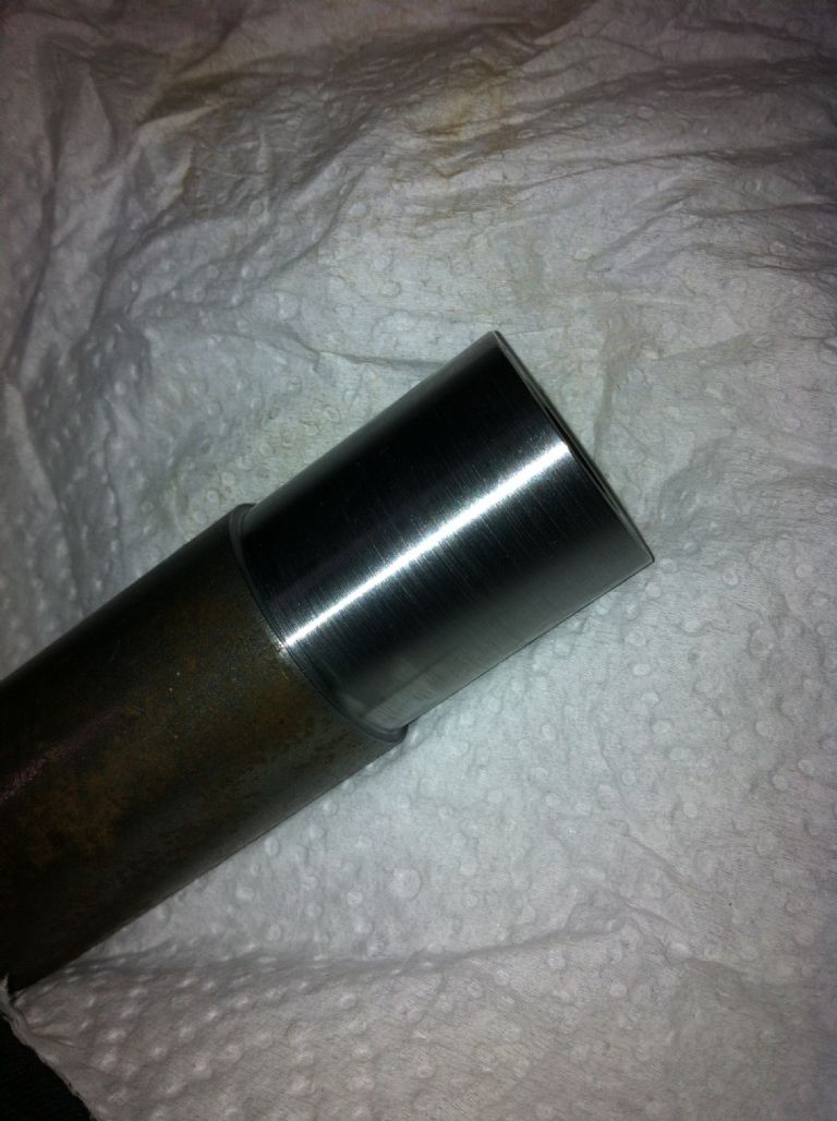
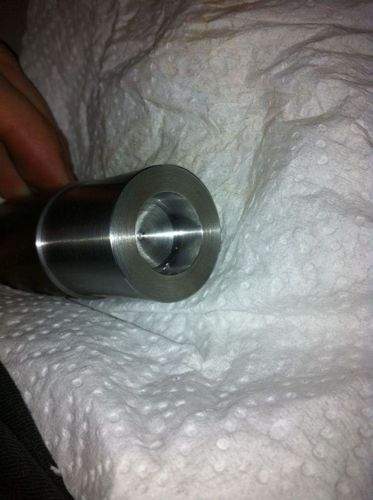
                              This is what I now have…. a piece of EN1A lying around.

                              Outside diameter…

                              img_0969.jpg

                              and bore…

                              img_0970.jpg

                              #116903
                              Lathejack
                              Participant
                                @lathejack

                                Hello Andy

                                The problem you have was one of many faults i had with a new Warco 1330 lathe that i bought from them several years ago, and it is not uncommon. The lathe shown in your link has the same apron as mine, so i assume your lathe does too, but if not the cause may still be the same.

                                You will find that the pitch of the banding is the same as the distance the carrage travels for every revolution of the feed shaft when longitudinal power feed is engaged. Behind the apron the feed shaft passes through a cast iron trough integral with the apron, the trough side walls are bored to support the feedshaft.

                                Inside this trough sits the steel worm gear, with the feedshaft passing through it, and this worm meshes with and drives a bronze worm wheel above it. Two or three faults can often be found here that can cause the banding, and you may have one or more.

                                The bores in the trough side walls can be oversize allowing the feedshaft to roll around as it rotates, taking the worm gear with it. The worm gear can also have a bore that is eccentric to its teeth, this gear can also be a sloppy fit on the feed shaft.

                                These faults cause the worm gear to go in and out of mesh slightly with the bronze worm wheel when power feed is used, so the carrage does not travel at a constant rate. It is a little hard to imagine this having much affect on the surface finish, but it does, and can show up even worse on softer metals such as aluminium and bronze.

                                One of my photo albums includes some of what i did to cure this problem. I also had to mount the worm gear on a mandrel and reskim the gear teeth concentric to the bore, there is not quite enough room to bore it out and bush it.

                                 It does not matter what feedrate you select, the carrage always travels the same distance per revolution of the feedshaft, so the pitch of the banding is always the same. The banding will show up more the finer the feedrate and the better the cutting tool.

                                Hope this helps.


                                Edited By Lathejack on 15/04/2013 01:05:02

                                Edited By Lathejack on 15/04/2013 01:16:26

                                Edited By Lathejack on 15/04/2013 01:20:39

                                #116905
                                Michael Gilligan
                                Participant
                                  @michaelgilligan61133
                                  Posted by Stub Mandrel on 14/04/2013 18:37:42:

                                  Andy,

                                  Some smaller lathes (like mine) don't have separate feedscrews and leadscrews. I see yours is a 1-ton monster with THREE 'lead feedscrews' according to the spec is that one for auto feed, one for metric and one for imperial?

                                  Neil

                                  .

                                  Neil,

                                  … looking at that spec sheet

                                  I suggest that | Pitches of three feed leadscrews | 3 mm |

                                  should read | Pitch of the feed leadscrew | 3 mm |

                                  We can probably blame the "Grammar Checker"

                                  … I'm sure mine would make a mess of Chinese Grammar !

                                  MichaelG.

                                  #116951
                                  Ian S C
                                  Participant
                                    @iansc

                                    There is another thread on this subject. a year or two ago, but I can not find it.

                                    There was an item in ME a few (10 / 15)years ago, the cure was to isolate the motor from the lathe(motor mounted on back of the bed) with thick rubber sheet, and the bolt holes bushed with rubber tube. Also the V belts were replaced with link type belting. My own lathe does produce banding from time to time, I'v got the link belts, but have not got round to doing the rest. Ian S C

                                    #116997
                                    Sub Mandrel
                                    Participant
                                      @submandrel

                                      Michael/Andy,

                                      I think the clue is the geared arrangement for the cross slide.

                                      So screwcutting leadscrew and feedscrews for saddle AND cross slide, so that's three!

                                      Neil

                                      #116999
                                      Anonymous

                                        It's normal for the saddle and cross slide power feeds to be driven off the same feedscrew. A selector on the apron is used to select sliding or cross feed.

                                        Regards,

                                        Andrew

                                        #117074
                                        Sub Mandrel
                                        Participant
                                          @submandrel

                                          I don't disagree Andrew, i just think that's how they get to '3'!

                                          Neil

                                        Viewing 19 posts - 1 through 19 (of 19 total)
                                        • Please log in to reply to this topic. Registering is free and easy using the links on the menu at the top of this page.

                                        Advert

                                        Latest Replies

                                        Home Forums Manual machine tools Topics

                                        Viewing 25 topics - 1 through 25 (of 25 total)
                                        Viewing 25 topics - 1 through 25 (of 25 total)

                                        View full reply list.

                                        Advert

                                        Newsletter Sign-up