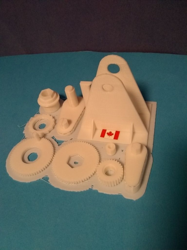
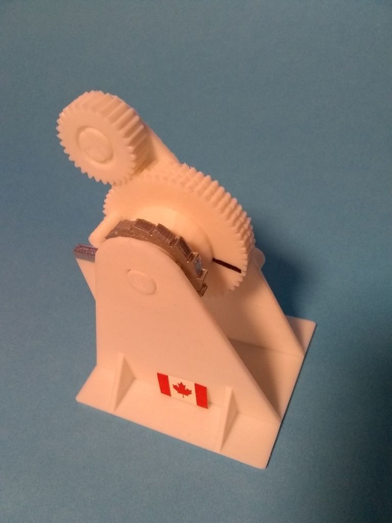
Balzer relieving attachment working model
Balzer relieving attachment working model
- This topic has 28 replies, 9 voices, and was last updated 10 January 2020 at 22:25 by
Pete Rimmer.
- Please log in to reply to this topic. Registering is free and easy using the links on the menu at the top of this page.
Latest Replies
Viewing 25 topics - 1 through 25 (of 25 total)
-
- Topic
- Voices
- Last Post
Viewing 25 topics - 1 through 25 (of 25 total)
Latest Issue
Newsletter Sign-up
Latest Replies
- Bad design, or am I missing something?
- Easiest/cheapest source of R8 socket
- Even the Dealer Didn’t Know!
- More BBC Masterchef woes…
- Sat nag
- What Did You Do Today 2025
- New member
- Boiler Design – issue 4765
- Paint stripper does not do what it says on the tin
- Please direct me to where I can find an engineer to do some bespoke work


