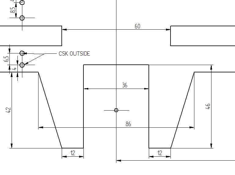
I notice on the Drawings on the digital format of M E their are a few dimensions missing around the horns on the frames . Am I too keen or will these become apparent later in the series !?! Before I cut metal I prefer to model it in Inventor .
Enjoying what I have seen so far !
Chris
Hi Chris, yep you right I missed a few there. All the articles are written to complete a section of the build so I generally won't go back and say drill holes in a completed frame. If you find any dimensions missing please let me know and I'll add the drawings to the forum and update mine. Most of the missing dimensions will be because the item was laser cut using a DFX or 3D printed for the patterns.
Please post some pics of your progress! Can even add it to the series as a post script…
Thank you Luker for your prompt reply. Yes will post some photos / images as I progress. I was planning to mill the frames on the miller at work, the controller has the facility to convert DXF files to coordinates Hint !
hi my name is tom hardy and i propose to build a 5 inch ballaarat i am a member of the northern districts model engineering society in perth west australia i live an hour and half drive from the original ballaarat in busselton is it possible to obtain dxf file of the frames and other components to give to a local laser cutter.
Hi Tom, the DFX files for laser cutting are rather extensive and contain all the process specific tolerance and machining allowance built into the files. There is enough information for an unscrupulous commercial entity to use them to make kits at ridiculous prices to the detriment of the designer (and builders). I therefor will not give out the DFX files, but there is more than enough information in the series to draw them up yourself, or even better just let the laser cutting guys do it for you.
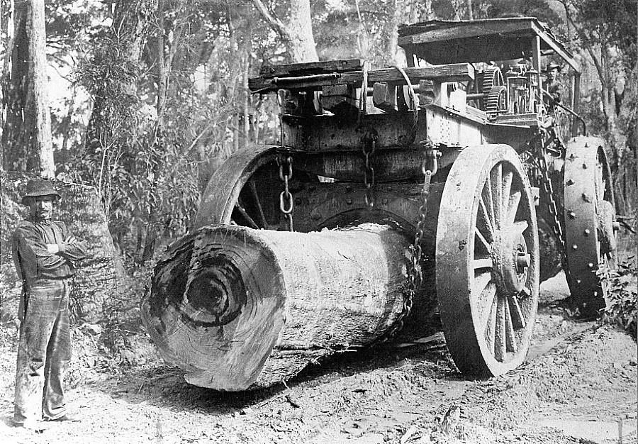
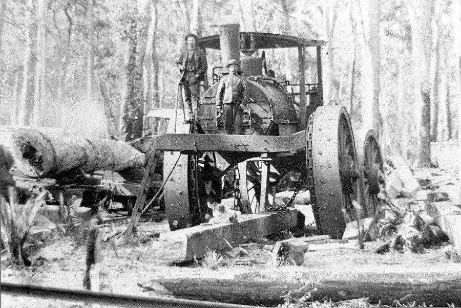
information on the ballaarat there is a book titled steam in the forests by mrh southecombe available from the chart and map shop fremantle wa this gives a comprehensive account of timber logging in wa
if you are looking for another project 3 steam whims were made in yarloop wa around 1900 a modeller in the netherlands loek proper built one in 1918 and there are 2 videos on you tube he got his information from the pickering brook heritage web site when googling steam whim model i have started to do a whim
Hi Tom, my next project is well on its way. Design complete, boiler, frames and all castings done. But these Whims look great! I won't tackle multiple projects at once but these will be added to my possible projects list!
The little Ballaarat goes to our track often, but last weekend there was a quiet time when I could play around a little. I raked the fire bare and waited for the pressure to dip below 30Psi (roughly, the loco has a commercial ME gauge soon to be replaced!). Added cold anthracite and set off… It kept that low pressure for a while on our long track then slowly started to build pressure and at the end of the run was on working pressure. I was pleasantly surprised by that little boiler and loco!
For the Wahya and Ballaarat I did some simulations and design work on the boiler and front ends; comparing these locos to the other locos I've built it looks like it’s paid off…
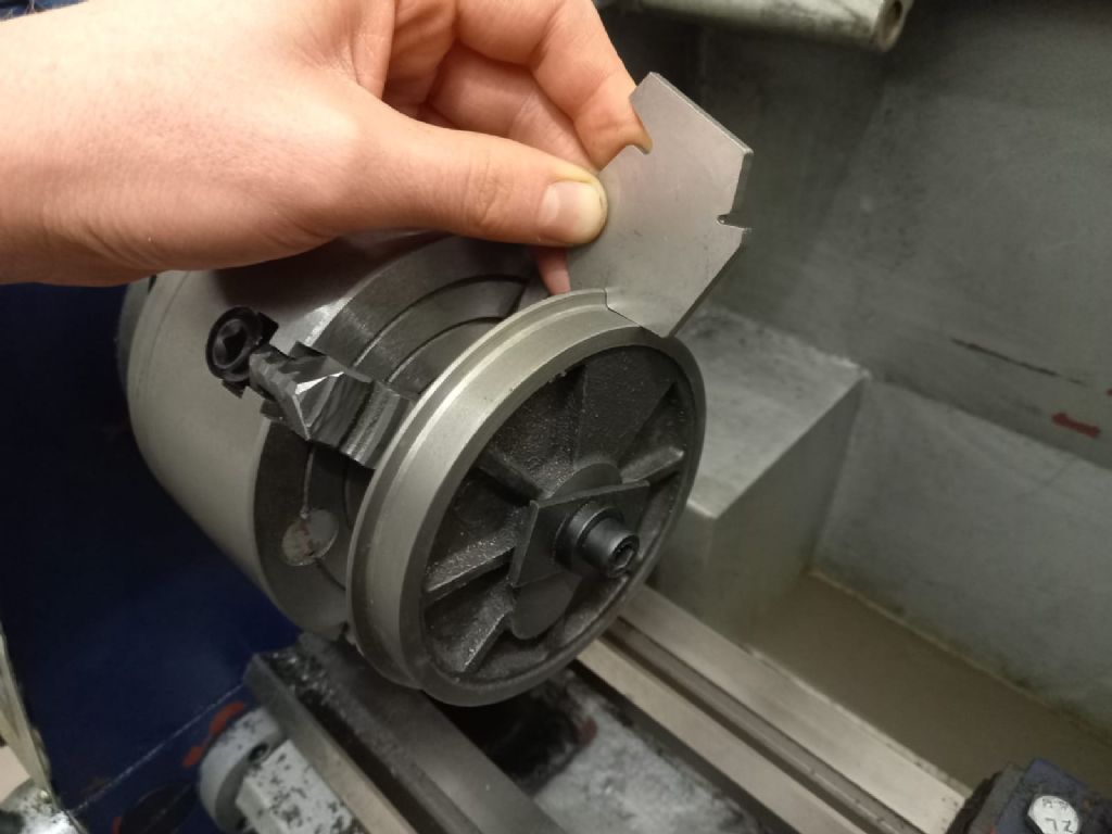
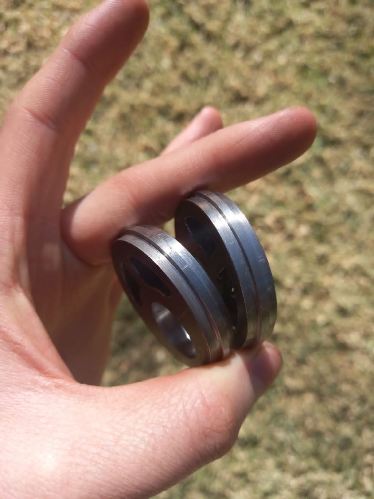
The young lad mentioned in the beginning of the Ballaarat series is moving along nicely with his build. Bearing in mind he never went to a technical school, nor has he decided to follow a career in engineering, his model engineering skills are moving along incredibly fast. I asked him to write a piece for our little club newsletter and one of his statements struck home and I thought it was rather inspirational: “This hobby sucks when you do things wrong the first time or two but it’s amazing when you finally get it right.” He sent me a picture of one of the wheels, machined according to the instructions in the articles. The picture shows him checking the profile with a gauge I designed to make life a little easier. Looks pretty good to me (in fact spot on!). The eccentrics came out nicely as well. Well done, young man!
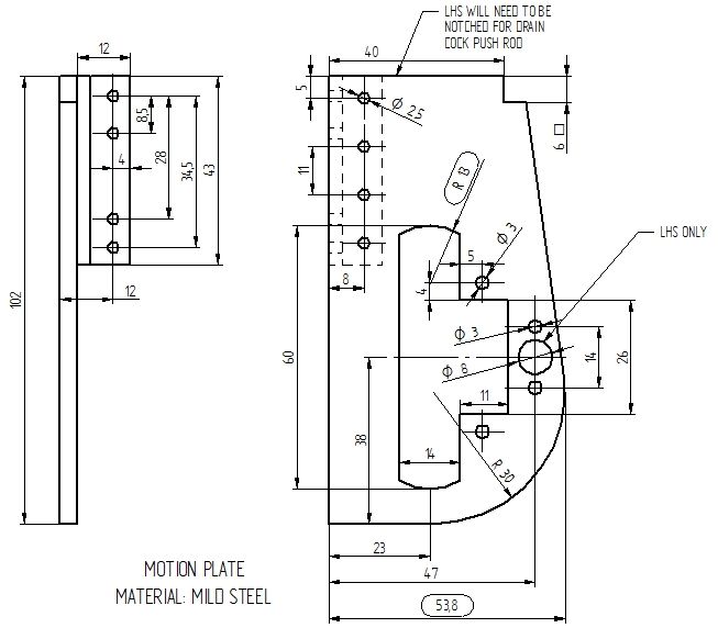
is it possible to give me measurements of the motion plate
tom
Of course! I think I've added the missing dimension you're looking for, and updated the drawing (and mine). There's bound to be more as you go; please give me a shout and I'll update the drawings, and add it to the forum. Please post pictures as you go!
In your intro to the Ballaarat you mention having your mentee complete a "wobbler". Do you have an article you've already written on that, or a drawing? Seems like a good idea as an intro machining project.
Ron
Hi Ron, I never did an article on the wobbler. It is very simple! It was designed to be made by sales guys that had never machined anything, for a course I presented many years ago (for fun). There are many better designs out there, but if you want the drawings you are welcome to them. I might need to make a few notes for you, as the drawings specifically omit one dimension that was up to the class to work out (and find). There were a couple of other outcomes of the course besides the machining for example engine balance, low vs high rev's etc. One of the builds are in the video below…
Thanks for your design of this interesting loco Luker. I know that it ran on 3’6 gauge, but what scale did you use? I can’t find it in the articles. Dividing 42” by 5” gives 1 in 8.4, but what did you do? f
Hi Simon, yep you spot on, I used 8.4. I model in metric so I use a gauge rail multiplier and generally clean up the dimensions as I build. This is a little different to the designers that model inch to the foot. There are a few notable deviations including the wheel and flange which is to the ME standard and the cylinders aren't to scale. The cylinders are different because scale cylinders would have been too small for the boiler etc. I do a few simulations and based on the results of those the boiler is matched to the smokebox and cylinders etc. Then all the linkages are updated for a hard working loco (out track is a little rough!).
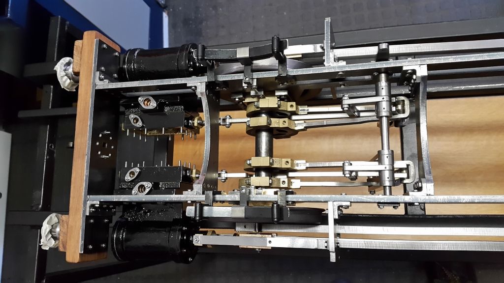
The Gooch valve gear and links for the Ballaarat are detailed in the new ME (4677). I thought a small animation of the linkages in motion would be nice…
Lovely animation; horrendous valve gear. I enjoyed the article. Double expansion links. What a pain!
Thanks Simon, the Gooch valve gear is interesting to design, but modern simulation techniques make life a little easier. I would not like to design this valve gear with just a drawing board! It is incredibly interesting to see all the linkages working in-between each other. I must say the Ballaarat valve gear hasn’t given me any of the issues I’ve read about, even back notching (within reason) is as good as any of my other locos. In fact it behaves the same as my Walschaerts fitted 3.5g 2-6-2 loco in terms of coal consumption, water consumption etc. (this loco has similar design tractive effort, boiler size etc.).
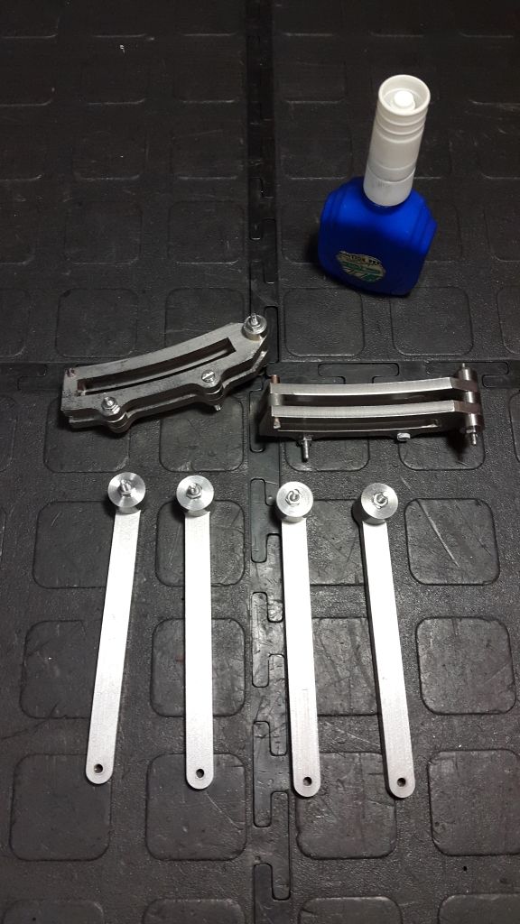
The expansion link wasn’t that difficult to make, it was easier than the normal type because the laser cut surface was of better quality (thinner section). If I were to machine these from scratch they would be held together and match machined so not much extra work. Some pics…
Thanks Luker, that makes it clear. It could be a quick build because it only has the essentials, but it is quite a smalll loco at that scale.
Took me 9 months from first casting to first steam test …
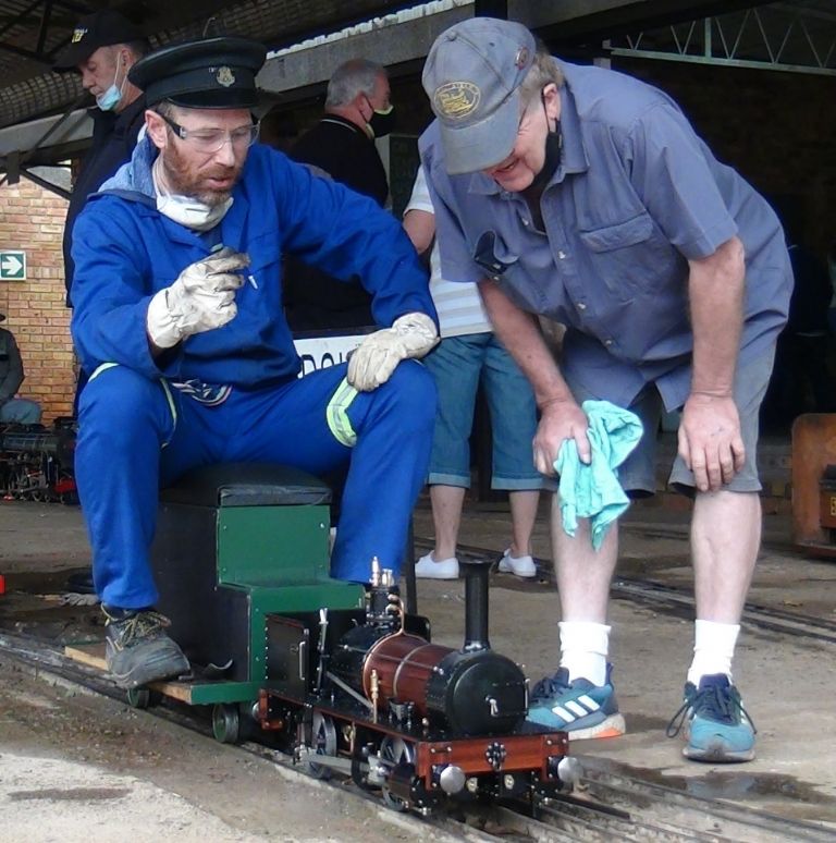
Concerning the size of the Ballaarat; there’s a picture earlier in this thread of the loco with two adults standing beside it to give an idea of scale. It will happily pull 2 large adults on our track which has an interesting 1:50 gradient for 60m, under trees that tend to dust the track with slippery juices. My 2-6-2 tends to slip here but the Ballaarat doesn’t. I'm reasonably sure it will haul more but my driving cart only takes two…
Great photo that shows the set up perfectly. The long radius rods would reduce angularity problems so perhaps why you find it works well in practice. Yes, with 4 links, you’d want them laser/water/wire cut.
The boiler scales to a little under 4”. Did you use 4” tube or roll the barrel?