Baldwin Gas Mechanical Throttle

Advert

Baldwin Gas Mechanical Throttle

Home Forums Work In Progress and completed items Baldwin Gas Mechanical Throttle

Viewing 7 posts - 1 through 7 (of 7 total)
  • Author
    Posts
  • #287602
    Steve Addy
    Participant
      @steveaddy35670

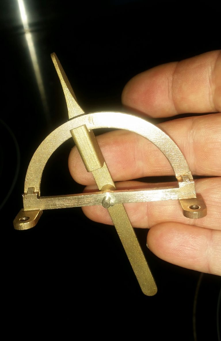
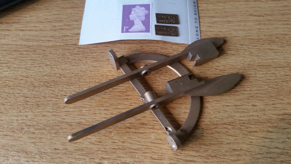
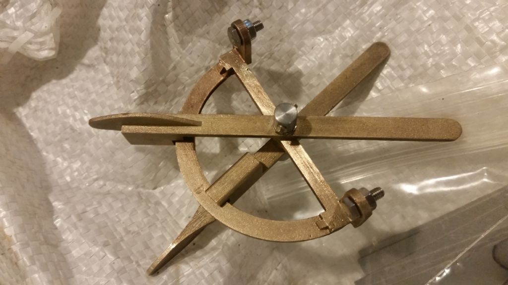
      A couple of pictures of the throttle and magneto quadrant with the levers. One photo includes both lamp plates before they were fitted, resting by a 1st class postage stamp.

      Magneto lever and throttle quadrant

      Throttle parts

      Advert
      #31153
      Steve Addy
      Participant
        @steveaddy35670

        More silicon bronze investment castings from wax prints

        #288011
        Steve Addy
        Participant
          @steveaddy35670

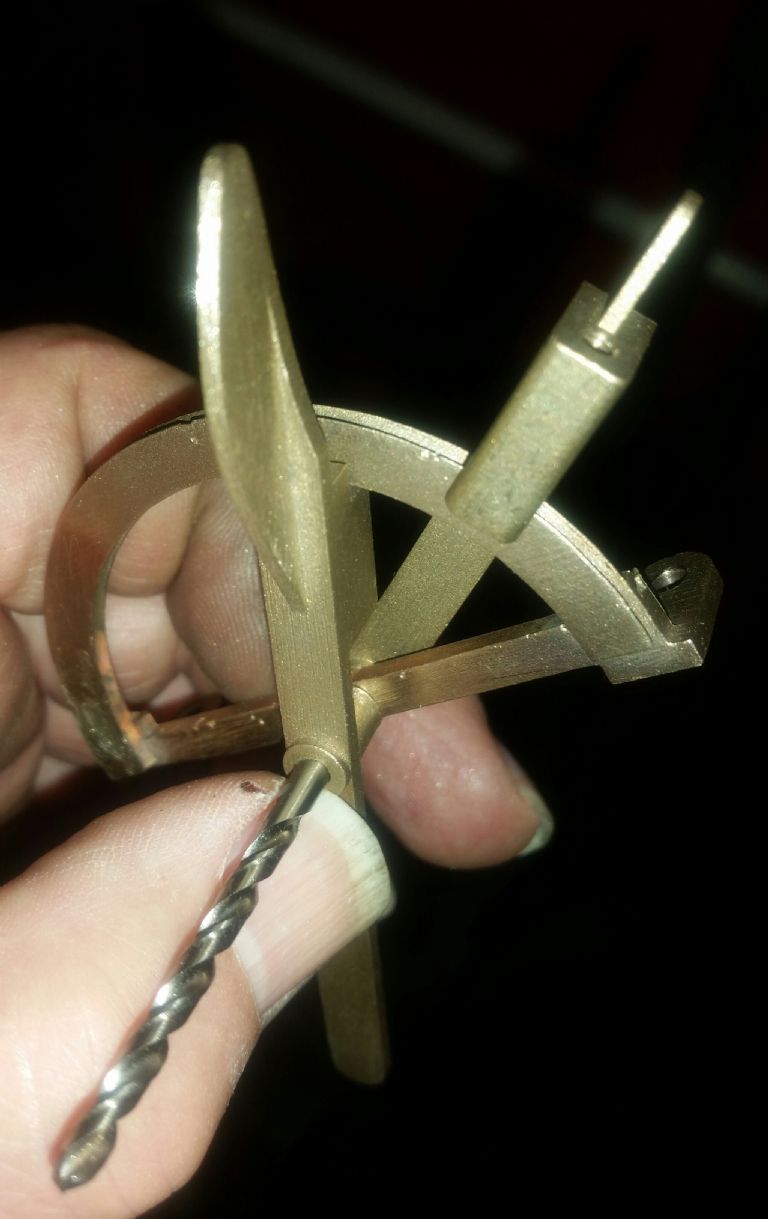
          I've done a bit more today, finalised the drawing of the spring loaded friction parts and drilled and tapped both levers to take the bits. The rear one is drilled through and has a plug, but the front one is blind and has a drilled bush to guide the business end of the pin. I'm going to cheat and put some wavy washer friction in the pivot shaft too. I hope to make them tomorrow.

          Throttle Parts 2

          Edited By Steve Addy on 09/03/2017 20:24:02

          #288047
          OldMetaller
          Participant
            @oldmetaller

            Hi Steve, I wasn't quite sure about the quadrant parts at first, but I've got it now!

            I didn't realise the lamp plates were that small!

            Good work!

            Regards,

            John.

            #288180
            Neil Wyatt
            Moderator
              @neilwyatt

              Very nice!

              Neil

              #288278
              Steve Addy
              Participant
                @steveaddy35670

                Thanks chaps.

                I have ordered a bit of 3mm precision ground steel for the pivot. I got the spring loaded bits made and fitted yesterday. Making daft little bits in a 5" centre lathe with a top speed of 800 isn't a lot of fun.

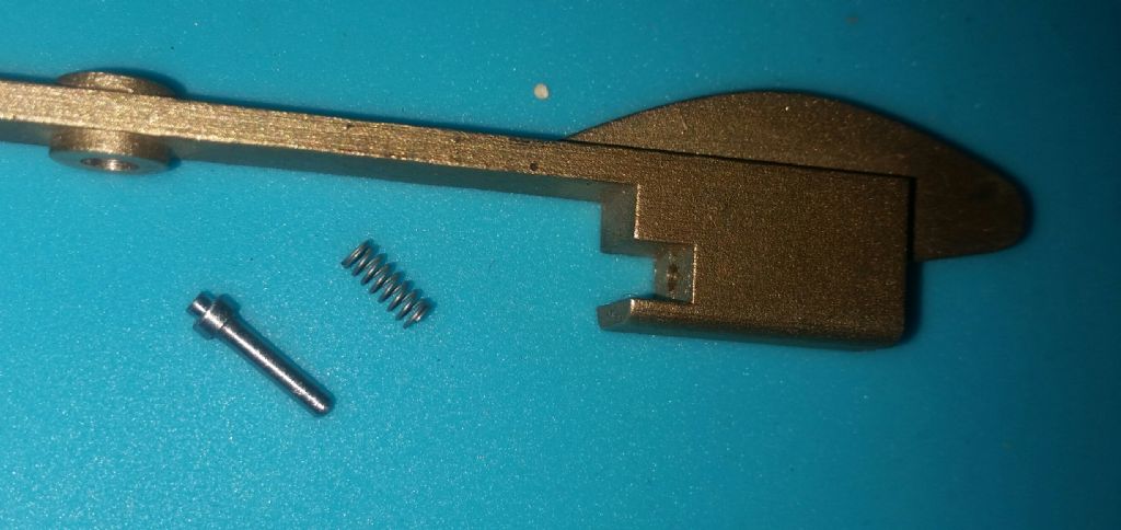
                I just need another turn of thread in the lever with the tapped hole in the picture above, to increase the spring pre-load slightly. I managed to use the runners off the nameplates to make the "bungs", so they are silicon bronze too.

                This is one of the friction pins and the spring, 2.2mm x 5mm long.

                Friction pin and spring

                Steve

                Edited By Steve Addy on 11/03/2017 13:25:07

                Edited By Steve Addy on 11/03/2017 13:26:08

                #289023
                Steve Addy
                Participant
                  @steveaddy35670

                  Well the 3mm ground steel arrived this week and I have made the pivot shaft and end nuts. These have wavy washers under them to provide a bit more friction than the friction pins in the levers alone can provide. I have cross drilled the nuts 1.4mm today to fit M1.4 setscrews to prevent them from undoing.

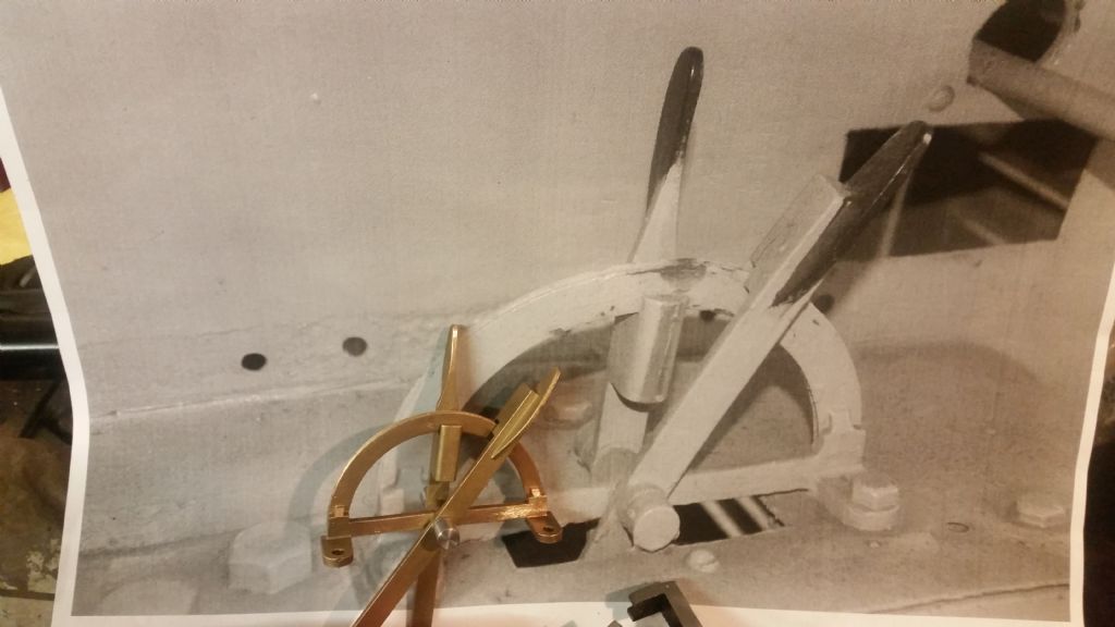
                  First image shows the assembly before cross drilling on a print of the full size parts, second one is the almost finished job. It just needs the link to the throttle control potentiometer finalising and then the lever drilling and pruning to suit.

                  Model throttle on picture of real one

                  Throttle almost finished

                Viewing 7 posts - 1 through 7 (of 7 total)
                • Please log in to reply to this topic. Registering is free and easy using the links on the menu at the top of this page.

                Advert

                Latest Replies

                Viewing 25 topics - 1 through 25 (of 25 total)
                Viewing 25 topics - 1 through 25 (of 25 total)

                View full reply list.

                Advert