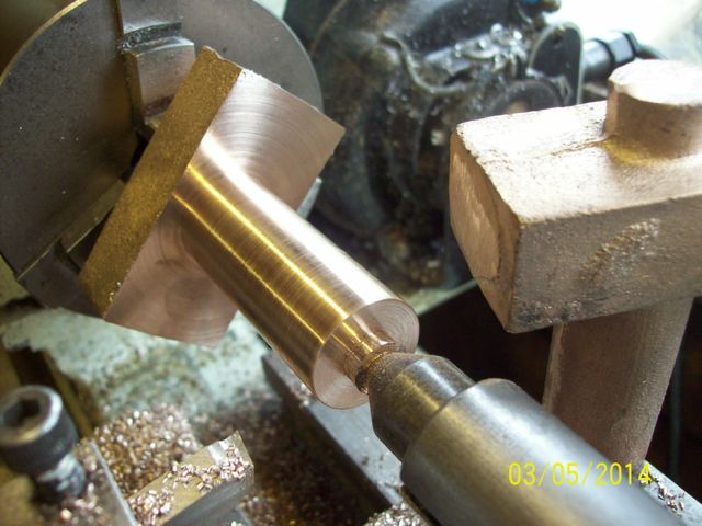
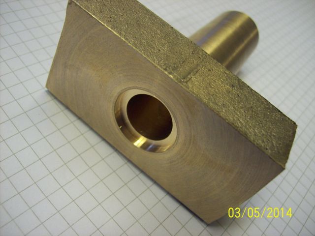
Just shipped off a pair of axle pumps for a client, who supplied the body castings and drawings. The phosphor bronze body castings were good apart from some pitting on just one face which could not be machined out and can be seen in the penultimate photo. The handy rear spigot was used in the chuck whilst turning the barrels with centre support.
After this the castings were reversed for drilling and reaming the bores, followed by turning a recess for an 'O'ring which seals the body to a cross-member between frames.

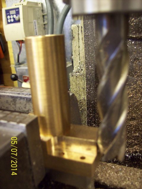
Body exteriors were then milled to size and each drilled for eight mounting bolts. Body depth is ¾" and the drawing called for each pair of bolt heads to sit in a recess ½" deep. This was all very well when the bodies were made in two parts, the barrel being a separate piece silver soldered on later. Now the supplier has incorporated both items into one casting, so a long-reach end mill is required.

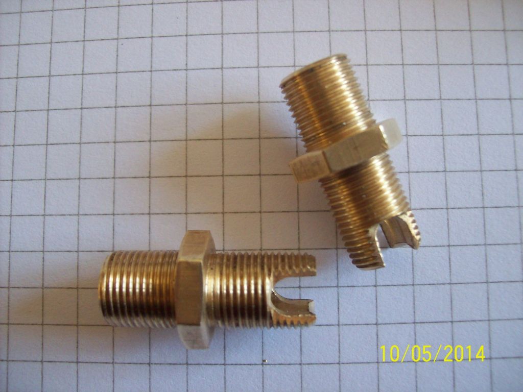
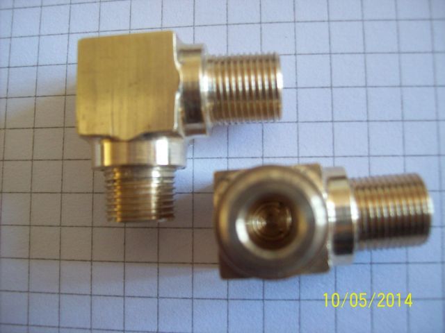
I confess that I chickened out of going very much deeper than this picture shows, with client's consent. The body ends were drilled and tapped ⅜' x 32 with plain passages to house stainless balls acting as non-return valves. Strangely, the top fitting had a plain internal end that seemed to me to be risking an inadvertent block if the ball was carried up to it by the flow. the resultant hydraulic lock would cause all sorts of damage, so I made the fittings with side relief to avoid the risk altogether.

The bottom fitting, the inflow port, is also a right-angled bend, so was a nice little turning exercise, tweaking the 4-jaw chuck to get diameters precisely centred within the 1' x ½" bar stock.

Here the valve ball seats on the fitting, and is prevented from entering the cylinder by a pin fixed across the body passage.
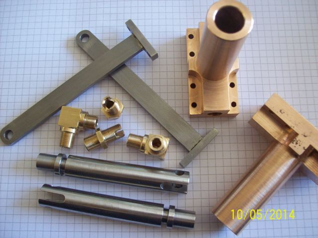
Other parts include the two rams in stainless steel, each grooved for a single 'O'ring, and connecting rods from two mild steel pieces silver soldered together. The drawing showed a rectangular hole in the con-rod base to accept the flat rod, but I drilled a round hole and tuned a matching spigot on the rod end; much simpler and quicker.

Note the pitting on one body face, mentioned earlier. A pity, but purely cosmetic.
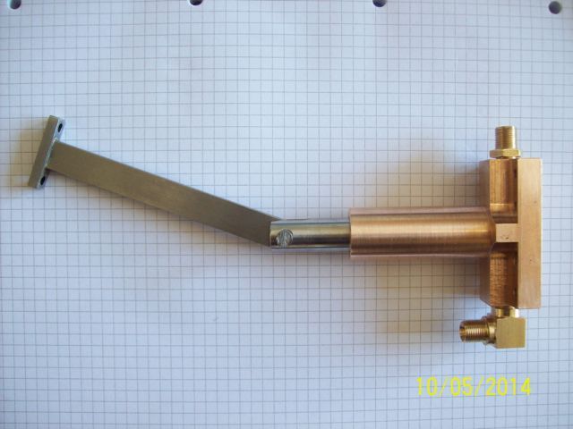
The final picture shows the assembly of one pump, probably exaggerating the con-rod angle somewhat.
I'd like to know if anyone has actually experienced problems with the top valve, such as I foresaw. Perhaps I was being a little paranoid, but when it's someone else's money, pride and joy at risk I prefer to be over cautious.
Thanks for viewing,
Ken.
John Baguley.


