Are the Electrics Right in ME4575?

Advert

Are the Electrics Right in ME4575?

Home Forums Model Engineer. Are the Electrics Right in ME4575?

Viewing 22 posts - 1 through 22 (of 22 total)
  • Author
    Posts
  • #330459
    SillyOldDuffer
    Moderator
      @sillyoldduffer

      I've just been reading Part 2 of 'Lathes and more for Beginners' starting Page 832 of ME4575, which arrived today.

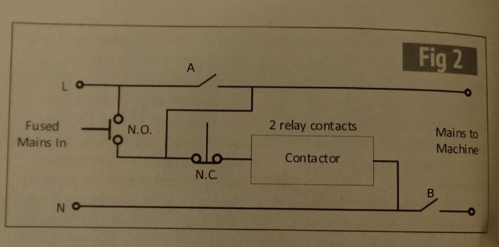
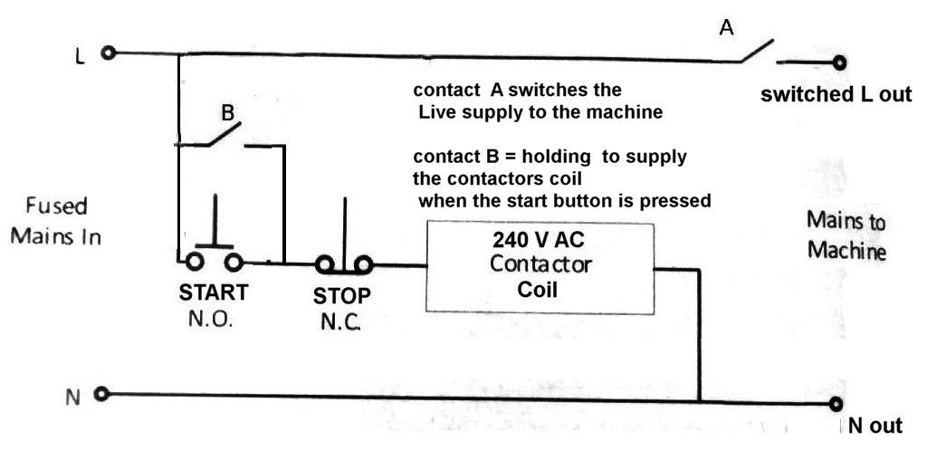
      I'm not sure I understand the Figure 2 circuit diagram – is it me, or have the gremlins struck again?

      dsc04973.jpg

      Firstly, the switch I've marked A and B in the photo. From the text which says 'For the on-off control do not under any circumstances use a single pole switch…' I believe A and B to be a two-pole linked switch. I'm uneasy that 'B' is downstream of the contactor. Wouldn't it be better for the contactor neutral to be disconnected entirely by the on-off switch?

      Secondly, the 'A' part of the on-off switch doesn't remove Live from the contactor once the contactor's Normally Open contact is closed.

      Thirdly, does the circuit as drawn work at all? Doesn't putting power on the contactor coil as shown via the normally closed contact mean the contactor immediately disconnects itself rather than latching ON?  In other words, the contactor doesn't do anything – it's the on-off switch that does all the work.

      Happy to be told I'm wrong!

      Dave


      Edited By SillyOldDuffer on 04/12/2017 17:15:58

      Advert
      #37752
      SillyOldDuffer
      Moderator
        @sillyoldduffer
        #330460
        Thor 🇳🇴
        Participant
          @thor

          Hi Dave,

          I am no electrician, but if the N.O. switch is pressed then the contactor coil is energized and operates the A and B switch and the machine is powered. When you release the N.O. switch the contactor coil is still powered via the N.C. switch. When that switch is pressed the contactor loose power and A and B releases and powers off the machine. Does that make sense?

          Thor

          #330461
          Martin Cargill
          Participant
            @martincargill50290

            It does work but its an unusual way to wire a contactor. A and B are the contactors contacts. N.O. and N.C. are separate start and stop buttons.

            #330462
            Ian P
            Participant
              @ianp

              This looks like it could have been in the Morecombe and Wise sketch of 'playing all the right notes, but not in the right order'!

              I have not seen the ME article so cannot add any valid comment other than its not something I would want in my workshop

              Ian P

              #330463
              Anonymous

                It only tells part of the story.

                The "switches" A & B are actually the contactor contacts. The NO and NC switches are momentary pushbuttons. So with power applied nothing happens until the NO button is pushed. Then the contactor closes A & B, and the machine is powered. The NO button can be let go as the contactor is now powered via the NC button. To turn the machine off the NC button is pushed. If, while the machine is running, power is disconnected the contactor will open. When power is reapplied the contactor will remain open, and the machine will not start. Which is what you want.

                The implication is that mains isolator is elsewhere either on the machine, but is not shown. This is more akin to industrial practise.

                Confusing for a beginner? smile o

                Andrew

                Edit: Ian P – this is a standard industrial setup. It is how most of my machines are wired, via a contactor and momentary pushbuttons.

                Edited By Andrew Johnston on 04/12/2017 17:32:02

                #330465
                Ian P
                Participant
                  @ianp

                  I assume the contactor is only being used as a relay to perform the no-volt release function.

                  The momentary 'On' button carries (for a short time) all the surge current that the machine draws when it starts up, that in itself is not good practice but not as bad as leaving the live connected and opening the neutral line.

                  Ian P

                  #330466
                  Ian P
                  Participant
                    @ianp
                    Posted by Andrew Johnston on 04/12/2017 17:28:24:

                    It only tells part of the story.

                    The "switches" A & B are actually the contactor contacts. The NO and NC switches are momentary pushbuttons. So with power applied nothing happens until the NO button is pushed. Then the contactor closes A & B, and the machine is powered. The NO button can be let go as the contactor is now powered via the NC button. To turn the machine off the NC button is pushed. If, while the machine is running, power is disconnected the contactor will open. When power is reapplied the contactor will remain open, and the machine will not start. Which is what you want.

                    The implication is that mains isolator is elsewhere either on the machine, but is not shown. This is more akin to industrial practise.

                    Confusing for a beginner? smile o

                    Andrew

                    Edit: Ian P – this is a standard industrial setup. It is how most of my machines are wired, via a contactor and momentary pushbuttons.

                    Edited By Andrew Johnston on 04/12/2017 17:32:02

                    I have machines wired up with contactors and momentary switches, but not like that.

                    The control switches do not normally handle the motor current, that is what the contactor is for.

                    Ian P

                    #330467
                    SillyOldDuffer
                    Moderator
                      @sillyoldduffer

                      Thanks Thor and Martin : I misread Fig 2 big time! I thought the NO/NC were the contactor contacts and A/B the ON-OFF switch. Good job I wasn't wiring it up.

                      Dave

                      #330468
                      JasonB
                      Moderator
                        @jasonb

                        I think it is the way it is drawn


                        When NO button is pressed A & B close so the motor draws from the live top left straight through contactor contact "A" through the motor and then back out through Contactor contact "B" to Neutral Bottom left.

                        Switching current goes from live through NO and activates the contactor and then back out to neutral so does not see full load

                        Edited By JasonB on 04/12/2017 17:48:49

                        #330469
                        Journeyman
                        Participant
                          @journeyman
                          Posted by SillyOldDuffer on 04/12/2017 17:44:53:

                          … I thought the NO/NC were the contactor contacts and A/B the ON-OFF switch. Good job I wasn't wiring it up.

                          Dave

                          Problem is that it is only part of the circuit and doesn't appear to use standard circuit symbols.

                          John

                          Edited By Journeyman on 04/12/2017 17:49:11

                          #330471
                          Martin 100
                          Participant
                            @martin100

                            Posted by Andrew Johnston on 04/12/2017 17:28:24:

                            this is a standard industrial setup.

                            I beg to differ. Good (aka sane) practice would have the contactor coil energised from live by just a push button switch (start) , the latching action by a dedicated normally open contact on the contactor (either a dedicated main contact or an auxilliary contact) connected across it and the release (stop) by another push button switch that is normally closed with an emergency stop (also normally closed) in series from the other side of the contactor coil back to the other supply leg.

                            The load current for the motor goes from the supply, through the main contactor contacts to the final load and nowhere else.

                            Sharing the contacts on the contactor between the final load and the control is questionable and 'cheap' but wiring the control circuitry such that ANY final load current passes through the start button, even for a short period until the contactor latches, is beyond ridiculous to suggest as being "a standard industrial setup"

                            If you are switching a single phase load then three normally open contacts on the contactor are sufficient, (live, neutral and 'control'  ) for a three phase load then you'll need four nomally open contacts (three for the phases and one for the 'control'  )

                            Also just using a contactor without any motor overload relay is just plain cheap, many connect direct to off the shelf contactors, cost next to nothing and should, if set correctly protect your motor from overheating.

                            But single pole switches, even when wired correctly are single points of failure and for emergency stop functionality may, by themselves, not fully satisfy the requirements in an industrial installation.

                            (spelling!)

                            Edited By Martin 100 on 04/12/2017 18:37:17

                            #330472
                            Emgee
                            Participant
                              @emgee

                              Contacts at A are the control circuit Hold contacts but they are also switching motor FLC, the contacts at B are not required as the neutral from the coil can be direct connected.
                              IMHO the circuit as drawn is not only misleading it is incorrectly drawn.
                              The idea of a contactor is for no voltage release if power fails, also to switch the motor power through contacts that are rated to safely pass the motor FLC,
                              Tthe control cct is switched via NO contacts which close when the contactor is energised, the control cct will also be switched off by the current overload being operated, there is no O/L shown in the cct drawn.

                              Emgee

                              Martin pipped me to it by a few seconds.

                              Edited By Emgee on 04/12/2017 18:26:19

                              #330474
                              john swift 1
                              Participant
                                @johnswift1

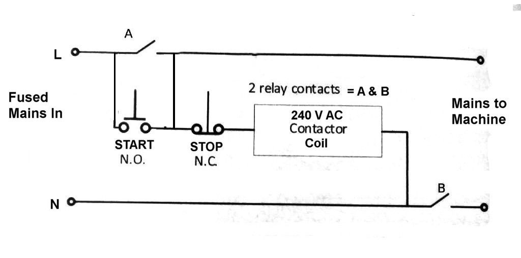
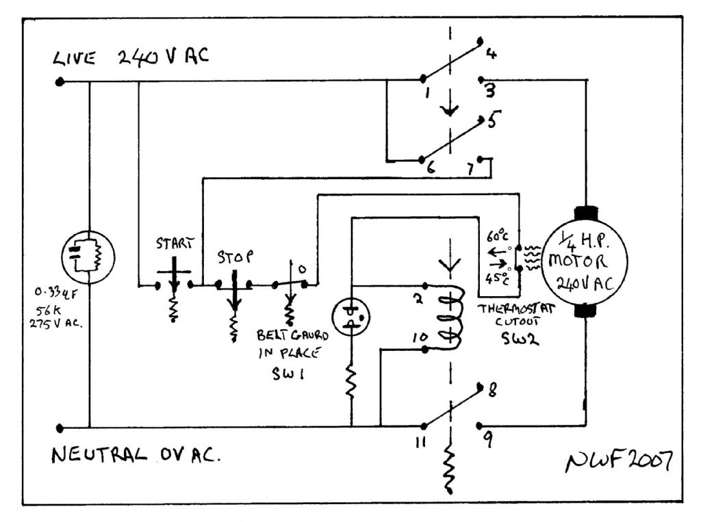
                                While the circuit shown in M.E will function

                                me4575  page 832   fig 2.jpg

                                I would not use it because the Live supply is connected to the machine when you press the START button before the Neutral !!!


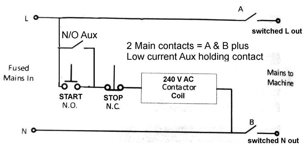
                                this is what I would of expected 

                                using two main contacts to switch the Live & Neutral to the machine and a low current N/O auxiliary to maintain the supply to the coil


                                revised   stop  start circuit.jpg

                                with this circuit both the Live & Neutral will be connected to the machine at the same time


                                John


                                Edited By john swift 1 on 04/12/2017 19:01:22

                                #330485
                                Neil Wyatt
                                Moderator
                                  @neilwyatt
                                  Posted by john swift 1 on 04/12/2017 18:57:49:

                                  revised   stop  start circuit.jpg

                                  With a 2-pole contactor I would have one wired as 'A' and the other as 'Aux'.

                                  Things like drill presses often use a single pole contactor, wired as the published diagram with just switch 'A'.

                                  N.

                                  #330497
                                  john swift 1
                                  Participant
                                    @johnswift1

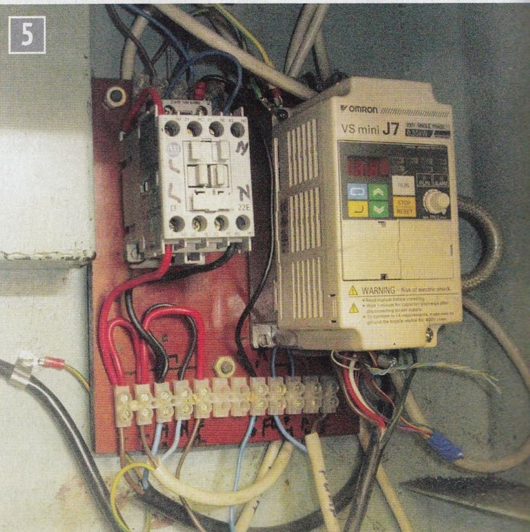
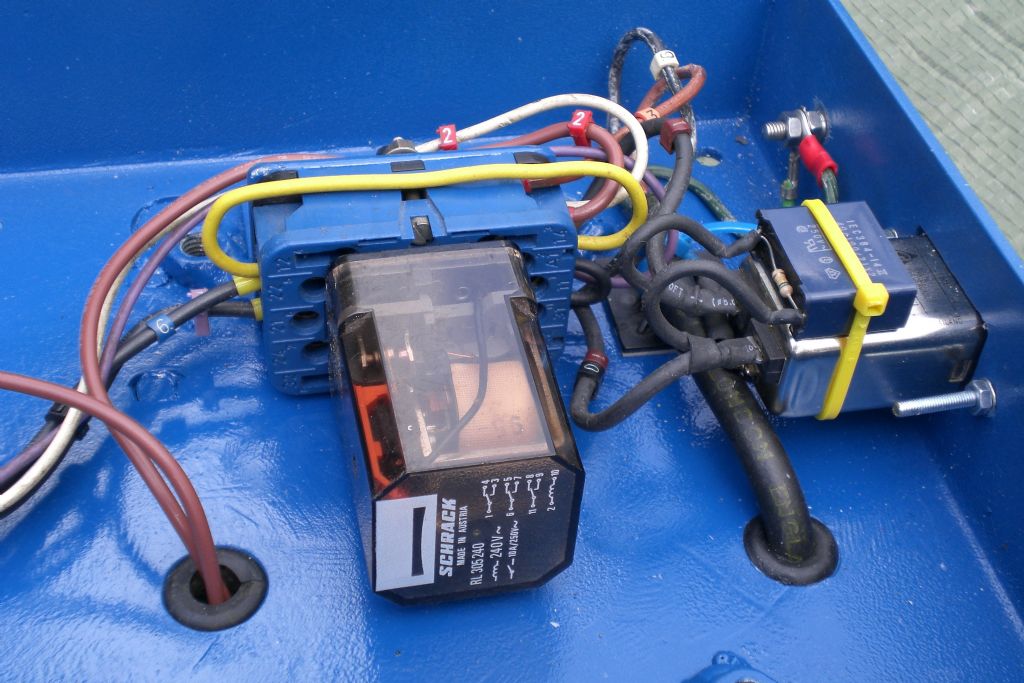
                                    my second diagram is correct when your using the contactor in figure 5 with 4 N/O contacts

                                    figure 5.jpg


                                    if your using a contactor with only 2 N/O contacts 

                                    this diagram goes with Neil's

                                    post

                                    revised  me  stop start circuit using  2 contacts.jpg

                                    John

                                    Edited By john swift 1 on 04/12/2017 20:36:36

                                    #330508
                                    Nicholas Farr
                                    Participant
                                      @nicholasfarr14254

                                      Hi, I agree that the circuit will work, but it is not drawn very clearly to my mined and like John Swift 1, I would not use it. John's circuit is basically the same as one that I drew up and used for a small sensitive bench drill I made up 10 years ago. Mine has a couple of extra safe guards in the circuit and uses a three pole relay. While I don't claim it to be using all the standard symbols, I think it is clearly understandable.

                                      nvr01.jpg

                                      drill07.jpg

                                      Works OK and is fairly compact and was not very expensive.

                                      Regards Nick.

                                      Edited By Nicholas Farr on 04/12/2017 21:59:10

                                      #330512
                                      Brian Sweeting 2
                                      Participant
                                        @briansweeting2

                                        Looking at Fig 2 in the original post I would consider it dangerous because even in the 'off' position there is still the potential for a voltage to reach the motor.

                                        Although the neutral should be at 0 volts a fault upstream would feed through the relay coil to the live feed to the motor or your fingers if you are during some wiring mods at the time.

                                        #330542
                                        Brian G
                                        Participant
                                          @briang
                                          Posted by Brian Sweeting on 04/12/2017 22:21:22:

                                          Looking at Fig 2 in the original post I would consider it dangerous because even in the 'off' position there is still the potential for a voltage to reach the motor.

                                          Although the neutral should be at 0 volts a fault upstream would feed through the relay coil to the live feed to the motor or your fingers if you are during some wiring mods at the time.

                                          Isn't that what the isolator is for? I wouldn't like to work on anything only separated from the mains by a contactor – if the neutral breaks correctly but the live contacts have welded, the motor would be live even though it had stopped. (Although this wouldn't happen in Fig.2 as the contactor is fed from the live contacts, so if the live contacts had welded the motor would re-start immediately the N/C button was released.)

                                          Brian

                                          #330553
                                          Clive India
                                          Participant
                                            @cliveindia
                                            Posted by Brian G on 05/12/2017 08:45:28:

                                            ……..Isn't that what the isolator is for? I wouldn't like to work on anything only separated from the mains by a contactor – if the neutral breaks correctly but the live contacts have welded, the motor would be live even though it had stopped. (Although this wouldn't happen in Fig.2 as the contactor is fed from the live contacts, so if the live contacts had welded the motor would re-start immediately the N/C button was released.) Brian

                                            Yes, agree, it is what the isolator is for.

                                            #330559
                                            Bikepete
                                            Participant
                                              @bikepete

                                              (deleted as on reflection possibly not helpful)

                                              Edited By Bikepete on 05/12/2017 11:22:15

                                              #330601
                                              Brian Sweeting 2
                                              Participant
                                                @briansweeting2
                                                Posted by Brian G on 05/12/2017 08:45:28:

                                                Posted by Brian Sweeting on 04/12/2017 22:21:22:

                                                Looking at Fig 2 in the original post I would consider it dangerous because even in the 'off' position there is still the potential for a voltage to reach the motor.

                                                Although the neutral should be at 0 volts a fault upstream would feed through the relay coil to the live feed to the motor or your fingers if you are during some wiring mods at the time.

                                                Isn't that what the isolator is for? I wouldn't like to work on anything only separated from the mains by a contactor – if the neutral breaks correctly but the live contacts have welded, the motor would be live even though it had stopped. (Although this wouldn't happen in Fig.2 as the contactor is fed from the live contacts, so if the live contacts had welded the motor would re-start immediately the N/C button was released.)

                                                Brian

                                                Agreed that the isolator should be used, perhaps my wording was unclear. In fig 2 the machine is not separated from the incoming neutral in the off state. 

                                                Any neutral fault upstream could be fed to the machine, unlikely, sure.

                                              Viewing 22 posts - 1 through 22 (of 22 total)
                                              • Please log in to reply to this topic. Registering is free and easy using the links on the menu at the top of this page.

                                              Advert

                                              Latest Replies

                                              Home Forums Model Engineer. Topics

                                              Viewing 25 topics - 1 through 25 (of 25 total)
                                              Viewing 25 topics - 1 through 25 (of 25 total)

                                              View full reply list.

                                              Advert

                                              Newsletter Sign-up