Arduinos and Microcontrollers ref: Rotary Table Mew 249

Advert

Arduinos and Microcontrollers ref: Rotary Table Mew 249

Home Forums Electronics in the Workshop Arduinos and Microcontrollers ref: Rotary Table Mew 249

Viewing 25 posts - 201 through 225 (of 243 total)
  • Author
    Posts
  • #309317
    Centurian
    Participant
      @centurian

      Thanks I followed your advice and download the "test" sketch and using the numbers obtained modyfied the 2.3 sketch. All now works according to Hoyle. Many thanks for your response. I thought I'd checked all the relevent threads, but you know what they say about thought.

      Advert
      #313720
      Centurian
      Participant
        @centurian

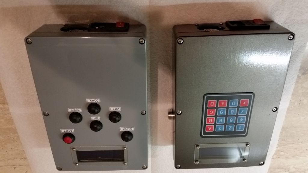
        Hi, Silly old Duffer, I have built both versions of the stepper rotary table box and they work wonderfully with one small exception. The keypad version causes a clunking sound in the stepper motor when running continuously and more pronounced when running an angle, say, 90 deg. The only change Iv'e made to your sketch is to change microsteps from 8 to 1. Iv'e made the corresponding change on the stepper driver board. Iv'e done this for both boxes. Needless to say when the same motor, used on the same rotary table, is run on the original box using Step indexer v2.3 there is no noise. Any suggestions? When I figure out how, I'll include pictures of both boxes.

        #313727
        Centurian
        Participant
          @centurian

          Here are the photos.20170824_190841.jpg

          Edited By Neil Wyatt on 24/08/2017 18:45:34

          #313730
          Centurian
          Participant
            @centurian

            Seems Iv'e been caught by the rotated picture gremlin. I tried to rotate it with my viewer software but it steadfastly remains upside down, so that's how it will stay, got better things to do.

            #313731
            Muzzer
            Participant
              @muzzer

              Centurian – are you using Windows 10?

              #313736
              SillyOldDuffer
              Moderator
                @sillyoldduffer

                Hi Centurian,

                Well one obvious difference is that yours is better made than mine.

                My initial reaction is that differences between the keypad version and the original version are mainly in the human interface logic and that shouldn't have an effect on the motor. (Famous last words.) The little bit of code that drives the motor is very similar in both versions. I didn't notice any unusual funny noises when l did my testing; Stepper motors do make odd noises. That said I need to refresh my memory. I'll look at the sketch to see if I can see anything in it that could cause your symptoms.

                The thing with the micro-steps is to make the values in the sketch match the switch settings on the controller. From memory though, a mismatch shows up by the motor turning wrong angles rather than making odd noises.

                Are the power supplies identical? I reluctantly used a 6A 12V LED driver because they're such good value, rather than best for the job. As stepper motors are pulse driven it's important to have enough amps available. The Stepper Motor notes recommend an unregulated supply for that reason. You could try adding an electrolytic capacitor across the PSU's output to act as a reservoir. (By the way, with hindsight, I wish I'd used a 24V supply. I think that's the best way to speed up the motor. )

                Happy to discuss further!

                Dave

                #313746
                SillyOldDuffer
                Moderator
                  @sillyoldduffer

                  Hi Centurian,

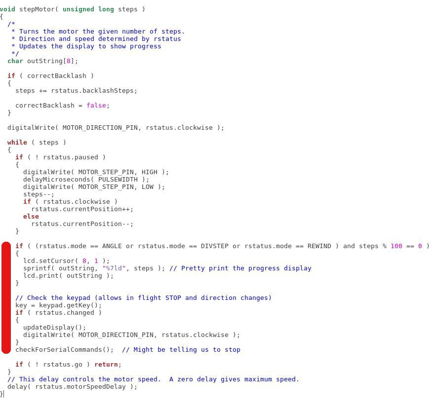
                  Something for you to try. I'd forgotten that my keypad version allows a motor operation to be interrupted and that it displays a progress report. It's possible that these features cause motor pulses to become irregular. The code that might cause a problem is in the stepMotor() function and is marked with a red bar below:

                  stepmotor.jpg

                  In ANGLE, DIVISION STEP and REWIND modes, the display is updated once every 100 steps. This is unlikely to be the cause. You could try increasing 100 to 10000 to see if that helps.

                  The keypad is checked after every motor step to see if the user has stopped the current operation. This could cause delays if the keypad is reporting key presses, because it's been lent on or is faulty. You could try commenting out key = keyPad.getKey().

                  checkForSerialCommands() reads the USB interface to see if a connected PC is trying to take control. Noise on the link could cause delays. As you're unlikely to be using remote control, the check can be commented out.

                  Another parameter you could play with is PULSEWIDTH. It controls the width of the pulse sent to the motor. By default it's set to 500 microseconds at the beginning of tyhe sketch. Possibly 500uS is a bit fast; try increasing it in steps of 25. The downside is that the motor will slow down.

                  Dave

                  #313751
                  Centurian
                  Participant
                    @centurian

                    Thanks for the replies. Firstly to Muzzer, no I am using Windows 7.

                    To Dave, I first tested the motors(NEMA 17) on a bench power supply before ordering the "working" supplies, and they drew less than 1.5 amps. I am therefor using the same 12V 5A supplies in both boxes. I have set the driver boards to 2A. One thing I should have mentioned that I think is very significant, is that the knock seems to occur on each rev. I.E. every 200 steps. I will try the software patches tomorrow, for it is now past my bedtime ( in Western Australia) One other thing I might try is to substitute the bench PS for the inbuilt one, just to eliminate that possibility. I will let you know how it goes.

                    Edited By Centurian on 24/08/2017 15:46:07

                    #313872
                    Centurian
                    Participant
                      @centurian

                      First my thanks to Neil for righting my wrong photos. Second to Silly Old Duffer, the mod to the sketch,i.e. changing the delay from 100 to 10000 worked a treat. Just to be sure I changed it back again and the noise re appeared, so it is now running at 10000, I suppose I should try various values, maybe later. Once again thanks.

                      #313873
                      SillyOldDuffer
                      Moderator
                        @sillyoldduffer
                        Posted by Centurian on 25/08/2017 11:49:38:

                        First my thanks to Neil for righting my wrong photos. Second to Silly Old Duffer, the mod to the sketch,i.e. changing the delay from 100 to 10000 worked a treat. Just to be sure I changed it back again and the noise re appeared, so it is now running at 10000, I suppose I should try various values, maybe later. Once again thanks.

                        Hi Centurian,

                        Glad that worked. Of all the possibilities I thought that least likely, though you spotting the noise occurs every 200 steps is a clue!

                        I've got the controller and motor in front of my computer ready to see if I can replicate the fault after lunch. Now you've very helpfully isolated it I can focus on the naughty code.

                        Many thanks for raising the issue. Any other feeedback would be welcome. I like to involve other people in what I do because they are much better at spotting my mistakes than I am! Not so easy to find volunteers now I'm retired.

                        Cheers,

                        Dave

                        #313876
                        Centurian
                        Participant
                          @centurian

                          I have been retired for 8 years now and if it wasn't for things like this I'd probably be in the ground by now. Its the reason for getting up in the morning. I have always found it very hard to proofread my own work as well. I'm not into programming despite spending many years in the computer service industry, but I'm learning.

                          #322526
                          Mike Blankley
                          Participant
                            @mikeblankley

                            Thanks to those who have got me started with an Arduino to control an ARC Stepper motor. I have it running per Carl's article, but the motor only turns at about 10rpm. I have it wired as a bipolar parallel.

                            Is it possible to increase the speed in the sketch..

                            Thanks, Mike

                            Edited By Neil Wyatt on 20/10/2017 16:53:20

                            #322535
                            SillyOldDuffer
                            Moderator
                              @sillyoldduffer

                              Hi Mike,

                              The motor normally runs quite slowly. I can't remember if 10rpm is typical or not but it might be. Assuming it's otherwise working correctly, there are two things you can try to speed it up:

                              (1)

                              Line 27 of the sketch says:

                              #define Microsteps 8

                              If you reduce the number, the motor will turn faster with bigger steps. Don't forget to alter the DIP switch settings on the controller to match. The downside is loss of accuracy. With zero micro-steps, a 200 step motor is only good for 1.8°

                              ———– and/or ——–

                              (2)

                              Line 73 says:

                              #define pulsewidth 2 // length of time for one step pulse

                              The #define sets the length of each pulse sent to the motor controller, which is the main limitation in code to the speed. By default it's 2mS per micro-step. You can experiment with shorter delays by changing Line 562 from

                              delay(pulsewidth);

                              to

                              delayMicroseconds( pulsewidth );

                              Now set the number in the #define pulsewidth statement (line 73) to microseconds, i.e 1500 for 1.5 milliseconds, 750 for 0.75mS etc.

                              The problem here is whether your motor can keep up with very short pulses. You may need to experiment to find the point at which the motor starts skipping steps and back off from that. Also, the article recommended a 12V supply, and making a stepper motor go fast really needs more volts. A 24V or 36V supply is more likely to drive correctly with short pulses than a 12V PSU. If you do increase the motor's supply voltage make sure the controller DIP switches are set to limit the current pulsed into the motor. Make sure the current limit is less than the maximum specified for your motor.

                              Hope that makes sense.

                              Dave

                              Edited By SillyOldDuffer on 20/10/2017 17:35:46

                              #322629
                              Mike Blankley
                              Participant
                                @mikeblankley

                                Dave. Thanks very much for your reply. I have been trying out your suggestions. I already had micro stepping set to 1. Changing to microseconds and from 2000 down to 1 has the motor spinning smoothly and at a suitable rate. Unfortunately it only runs at this speed when run continuously, not when dividing etc.

                                The motor is attached to a dividing head with a 60:1 worm and 5:1 gearing, so at 10 rpm would take about half an hour for one revolution of the chuck! Too slow even for me.

                                I wondered if you had any more ideas.

                                Thanks Mike

                                #322706
                                SillyOldDuffer
                                Moderator
                                  @sillyoldduffer

                                  Hi Mike,

                                  Sounds as if something's adrift, and it reminds me vaguely of problem I had ages ago. I'm just home after a tiring day and me brain is frazzled! I'll get my motor and Arduino out tomorrow and try and recreate the fault after a good sleep. Watch this space!

                                  Dave

                                  #322804
                                  SillyOldDuffer
                                  Moderator
                                    @sillyoldduffer

                                    Morning Mike,

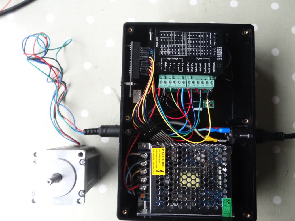
                                    I've shot myself in the foot in that I can't find my spare motor controller and I'm slightly reluctant to mess with the other because it's wired into a box with a keypad! dsc04383.jpg

                                    So my plan to mess with both wiring and software has gone adrift for the moment.

                                    However, I have my motor doing 60rpm at the shaft with a 200 step motor, 8 microsteps, and a 500μS pulse width. As expected, setting DIP switches for 4 microsteps doubles the speed , and 2 microsteps quadruples it. However, setting to 1 microstep stalls my motor, I guess because the pulses are too fast.

                                    The calculations in the Sketch for doing controlled moves like Division etc give wrong answers unless the controller and code both agree the same number of microsteps. Best to test in Continuous Mode as it just spins the motor without doing any sums.

                                    Can you provide details of the motor you're using and a photo of the wiring please?

                                    Another thought. You mention a 5:1 gearbox as well as a 60:1 table. Is the 5:1 gearbox necessary? It converts a long wait into an eternity and I doubt you need the extra torque it provides.

                                    Now I've got the bit between my teeth, I'm going to write a simple sketch to drive the motor flat out. It'll be fun to see how fast I can get mine to go.

                                    Dave


                                    Edited By SillyOldDuffer on 22/10/2017 12:22:51

                                    #322832
                                    SillyOldDuffer
                                    Moderator
                                      @sillyoldduffer

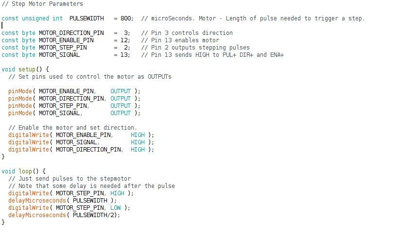
                                      Here's a sketch for testing a stepper motor & it's controller with an Arduino. It does nothing but send pulses to the controller and can be reconfigured to try different pulse rates, widths, and ON-OFF ratios.

                                      stepmotor_sketch.jpg

                                      Note that you may need to change the MOTOR_DIRECTION and other pin declarations to match your wiring. (My build doesn't use the same pins as the MEW article.)

                                      The values to play with are PULSEWIDTH and the value in the very last statement (delayMicrosSeconds)

                                      PULSEWIDTH determines how long the ON part of the pulse lasts, and the OFF part can be manipulated by dividing it. My motor mostly works with pulses that are OFF for about half the ON time.

                                      Experimenting with my motor and a 12V supply:

                                      • Sending ON pulses that are much too short (my motor < 350μS) causes the motor to stall and whistle,
                                      • Sending OFF pulses that are much too short causes the motor to stall
                                      • Likewise, sending ON/OFF pulses that are a bit too short causes the motor to miss steps. It runs, but slower, perhaps much slower than expected.
                                      • By experiment you can find the sweet spot for a particular DIP microstep setting on the controller. That is the combination of rate and On/Off time that runs the motor without losing steps. As this is likely to depend on load, it would be best to be conservative about racing the motor.
                                      • The sweet ratio isn't the same for across all microstep options.

                                      The values used in the MEW article are 'safe' in that they are unlikely to cause lost steps. You can speed the motor up by tuning the program, but take care! In theory, even better speeds are possible with a higher voltage supply but I've not been able to try it yet.

                                      Mike: I'm not sure if it helps but your symptoms match what happens when the motor is sent fast pulses. It may be revealing to experiment with the sketch to see what your motor does.

                                      Dave

                                      #322945
                                      Mike Blankley
                                      Participant
                                        @mikeblankley
                                         

                                        Hi Dave.

                                        Firstly thank you for your time and enthusiasm. I am experimenting with various settings and think that I can get the motor running satisfactorily in step mode. It will not then work continuously, but that doesn't matter. I have micro stepping set at 1 and pulse width at 200 microseconds. The motor hums nicely as it turns.

                                        I purchased the dividing head with the stepper motor and gearing already in place, and have been using it manually . A Division Master was a bit too pricey for me unfortunately, so yours and previous contributors articles have allowed me to use it with the stepper motor. I am really pleased.

                                        I think it fair not to waste your time on this anymore, although as a general point I have seen stepper motors turning at thousands of RPM and mine turning at 10 RPM. When buying one, how do you know how fast it will turn?

                                        Following your example, I think I will purchase an Arduino training kit and try to understand it a bit better.

                                        Thanks again, Mike.

                                        #322973
                                        John Haine
                                        Participant
                                          @johnhaine32865
                                          Posted by Mike Blankley on 23/10/2017 00:01:46:


                                          ….. I have seen stepper motors turning at thousands of RPM and mine turning at 10 RPM. When buying one, how do you know how fast it will turn?

                                          I think that's very much down to the driver and the way the motor is managed. Years ago in the early days of steppers when I was a PG at Leeds, Paul Acarnley and others was developing motors and drives and had motors running up from a dead standstill to hundreds if not thousands of RPM, with accompanying shrieks from the motor and driver, then slowing down to a dead stop after several minutes at exactly the same position. But you have to manage the acceleration and deceleration and various resonances in the motor very carefully to get the best performance, so I don't think it's simply a matter of buying the right motor. He has written a classic work on the subject but it's a bit pricey.

                                          #322995
                                          SillyOldDuffer
                                          Moderator
                                            @sillyoldduffer

                                            Hi Mike,

                                            No trouble – before your post I already had 'further investigation of stepper motors' on my ever growing 'to-do' list.

                                            Like you I was initially disappointed by the speed of my motor. Without thinking or checking I expected a few thousand rpm. It's not that simple, there's a bunch of trade-offs. Actually, it's other features of the stepper that are more useful in this application: it's ability to move to and hold a particular position rather than turn at speed.

                                            I've found the stepper / rotary table combination most useful cutting gears. Being a slack Alice, I waste time and material by losing count and other silly errors whilst cranking the table by hand. The stepper motor may be slow, but it doesn't make mistakes.

                                            It would be nice to have both speed and position out of a stepper motor and I haven't given up on the idea. If only I could afford the book mentioned by John Haine. £112 is a bit steep even as a xmas present. Might try the library.

                                            I recommend getting an Arduino training kit. They have lots of simple examples and help you avoid the common learner mistake of plunging straight into something complicated. (Like a rank beginner starting by trying to cut a non-standard screw-thread with his brand-new lathe! Don't ask how I know…)

                                            Dave

                                            #323006
                                            John Haine
                                            Participant
                                              @johnhaine32865
                                              Posted by SillyOldDuffer on 20/10/2017 17:35:13:

                                              The problem here is whether your motor can keep up with very short pulses.

                                              Actually the pulses trigger circuits in the driver IC, and are not applied direct to the motor. If you know which IC is used in your driver you can check the minimum pulse width, but I suspect it is only a few microseconds.

                                              #323064
                                              SillyOldDuffer
                                              Moderator
                                                @sillyoldduffer
                                                Posted by John Haine on 23/10/2017 10:42:25:

                                                Posted by SillyOldDuffer on 20/10/2017 17:35:13:

                                                The problem here is whether your motor can keep up with very short pulses.

                                                Actually the pulses trigger circuits in the driver IC, and are not applied direct to the motor. If you know which IC is used in your driver you can check the minimum pulse width, but I suspect it is only a few microseconds.

                                                Yes of course! I didn't think it through.

                                                With micro-stepping selected the controller output looks like a synthesised sine wave on my oscilloscope. It's made of spikes. I've no idea what happens to the waveform when it hits the motor coils but there must be limits to what the inductors will work with. Another 'find out how that works' addition to my 'to-do' list.

                                                Ta,

                                                Dave

                                                #323096
                                                John Haine
                                                Participant
                                                  @johnhaine32865

                                                  This is a chopped drive – the motor inductance smooths it out to approximately sinusoidal current.

                                                  #551762
                                                  Greensands
                                                  Participant
                                                    @greensands

                                                    I have just acquired a copy of MEW 249 to read up about the Arduino controlled indexer but am having problems in seeing exactly how the Uno Board is spaced off and attached to the lid of the enclosure. Could some kind soul please elucidate.

                                                    #551786
                                                    Journeyman
                                                    Participant
                                                      @journeyman

                                                      Four holes in the Uno board, 4 matching holes in the display and 4 holes in the case clear plastic between display and case also with four holes. Bolt through everything could put plastic tube spacers in but not really required if nuts are lightly tightened down.

                                                      Have a look at my version on ** Journeyman's Workshop ** click on the images to enlarge.

                                                      John

                                                    Viewing 25 posts - 201 through 225 (of 243 total)
                                                    • Please log in to reply to this topic. Registering is free and easy using the links on the menu at the top of this page.

                                                    Advert

                                                    Latest Replies

                                                    Viewing 25 topics - 1 through 25 (of 25 total)
                                                    Viewing 25 topics - 1 through 25 (of 25 total)

                                                    View full reply list.

                                                    Advert

                                                    Newsletter Sign-up