Hi Matt
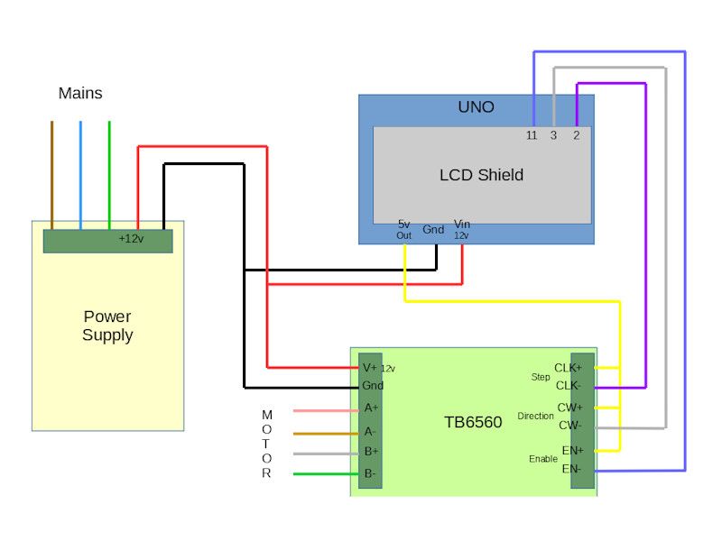
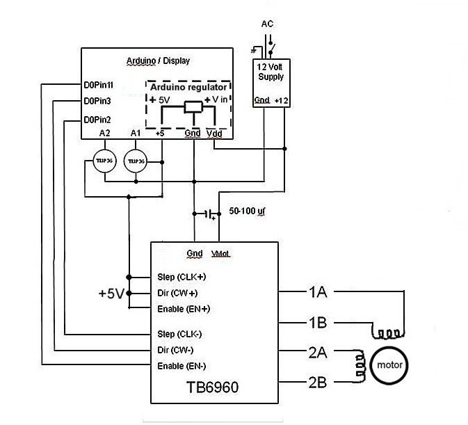
your wiring looks OK but you can do away with the USB cable by connecting the stepper drivers 12V supply to the ground and Vin terminals on the arduino
( the 5V regulator on the Arduino will drop the +12V down to +5V )


did you get the arduino to respond to the buttons correctly ?
from what I can see is the various manufactures don't stick to a single design for the boards they manufacture
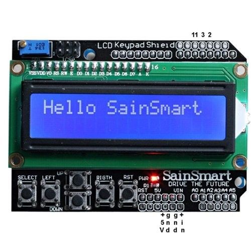
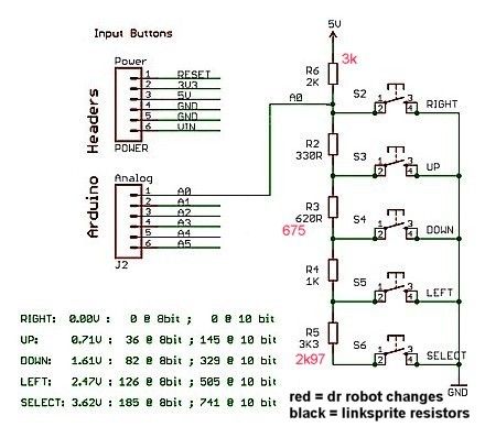
and for the LCD / button shield the variations in resistor values in the button ladder results in changes being needed to the sketch
( note not all LCD + button shields can use PWM brightness control for the backlight !! )

see this posted by sillyoldDuffer
http://www.model-engineer.co.uk/forums/postings.asp?th=122792&p=4
,
I've been playing too and have a similar problem. I'm pretty sure the issue is the bit of code that works out which key is being pressed. It's the very last function at the end of the Sketch and it looks like this:
int read_LCD_button() // routine to read the LCD's buttons
{
int key_in;
delay(ADSettleTime); // wait to settle
key_in = analogRead(0); // read ADC once
delay(ADSettleTime); // wait to settle
// average values for my board were: 0, 144, 324, 505, 742
// add approx 100 to those values to set range
if (key_in > 850) return NO_KEY;
if (key_in < 70) return RIGHT_KEY;
if (key_in < 250) return UP_KEY;
if (key_in < 450) return DOWN_KEY;
if (key_in < 650) return LEFT_KEY;
if (key_in < 850) return SELECT_KEY;
}
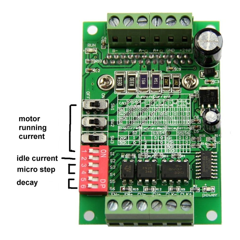
the 4 switches that control the motor current (SW1 to SW3 & S1) will need setting up fpr your motor

John
Edited By john swift 1 on 07/02/2017 18:31:45
John Olsen.


